
This week, we had to learn Eagle and use it to design the echo hello-world board with a couple additions. With things being a little crazy this week and given my non-existent experience with electronics, I decided to keep things simple and just add a button and LED.
Eagle took a while to get used to. I found the tutorial here to be incredibly useful in learning how to use Eagle. Other links that were helpful were:
Some things about Eagle that took me a while to realize but were incredibly helpful were:
My finished schematic and board images are shown on the right. Once I managed to figure out the idiosyncrasies of Eagle, it wasn’t too bad to get the board done. I don’t think I understand all the electronics rules and all yet, but I think that will come with time. I ended up adding my initials to personalize the board a bit and using Gimp to convert into the .png files for the Modela. The trick here was making sure to have the outline the right size and inverting image colors properly. Grace really helped me figure this out.


 Surprisingly, the tougher part this week was getting the board milled and soldered. Weird things kept happening with the milling. First, right before my board finished, the 1/32th bit broke on me and I had to restart the board from scratch. The second time around the double sided tape came off since the surface under the board had been used too many times and had a lot of scratches so I had to start over yet again. The third time around the Modela wasn’t cutting deep enough on one part of the board since the surface was uneven. I ended up taking the surface layer plate off and putting on a new one. This helped a lot and I finally got a board milled.
Soldering this week was also a struggle. I tried using a soldering iron I had at home and it didn’t have multiple temperature settings. It ended up being too hot and burned off some of the copper traces. I milled another board and tried again. Because the board was not wide enough, the FTDI connector kept falling off with any pressure and would rip off the copper traces with it. Finally, I decided to give it another try and made the outline wider this time to get a cleaner result. It looked a lot better! This time around, my soldering attempts also went a lot better. I was able to get the board stuffed and finished pretty quickly. I forgot to orient the LED properly at first but caught myself before doing too much damage. I think the hardest pieces were definitely the FTDI and the 20 MHz crystal for me. Thanks to Grace, Eric, Randi and Stefania for working with me and teaching me things!
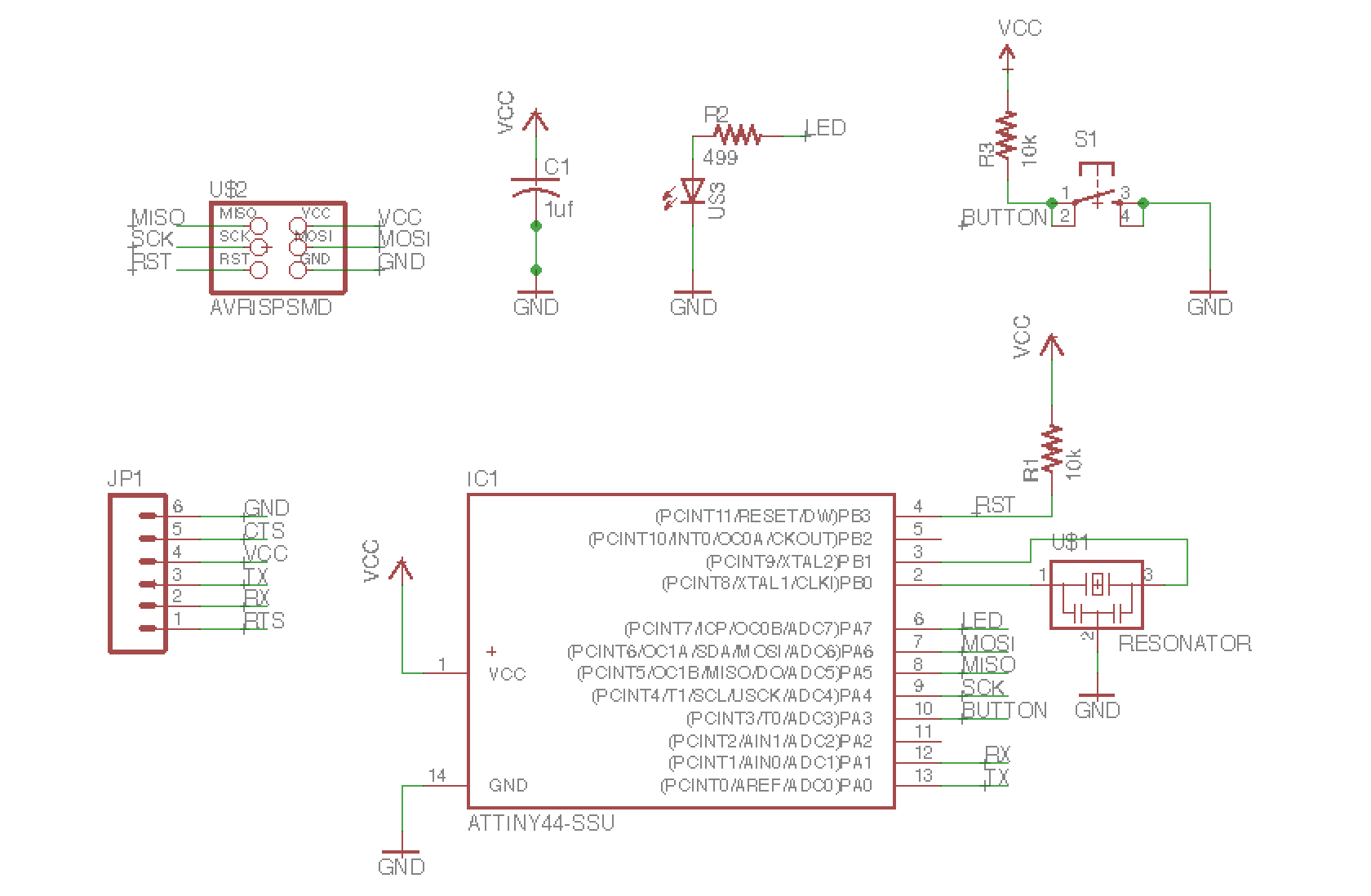
schematic in eagle
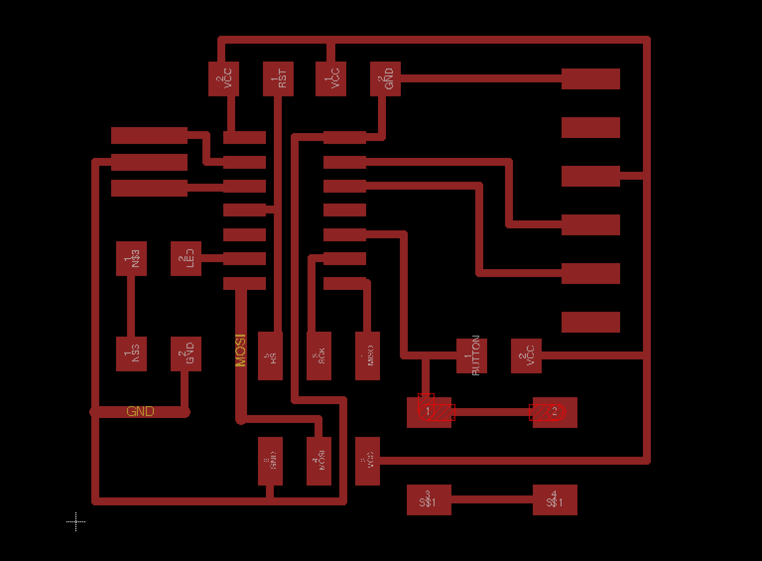
traces in eagle
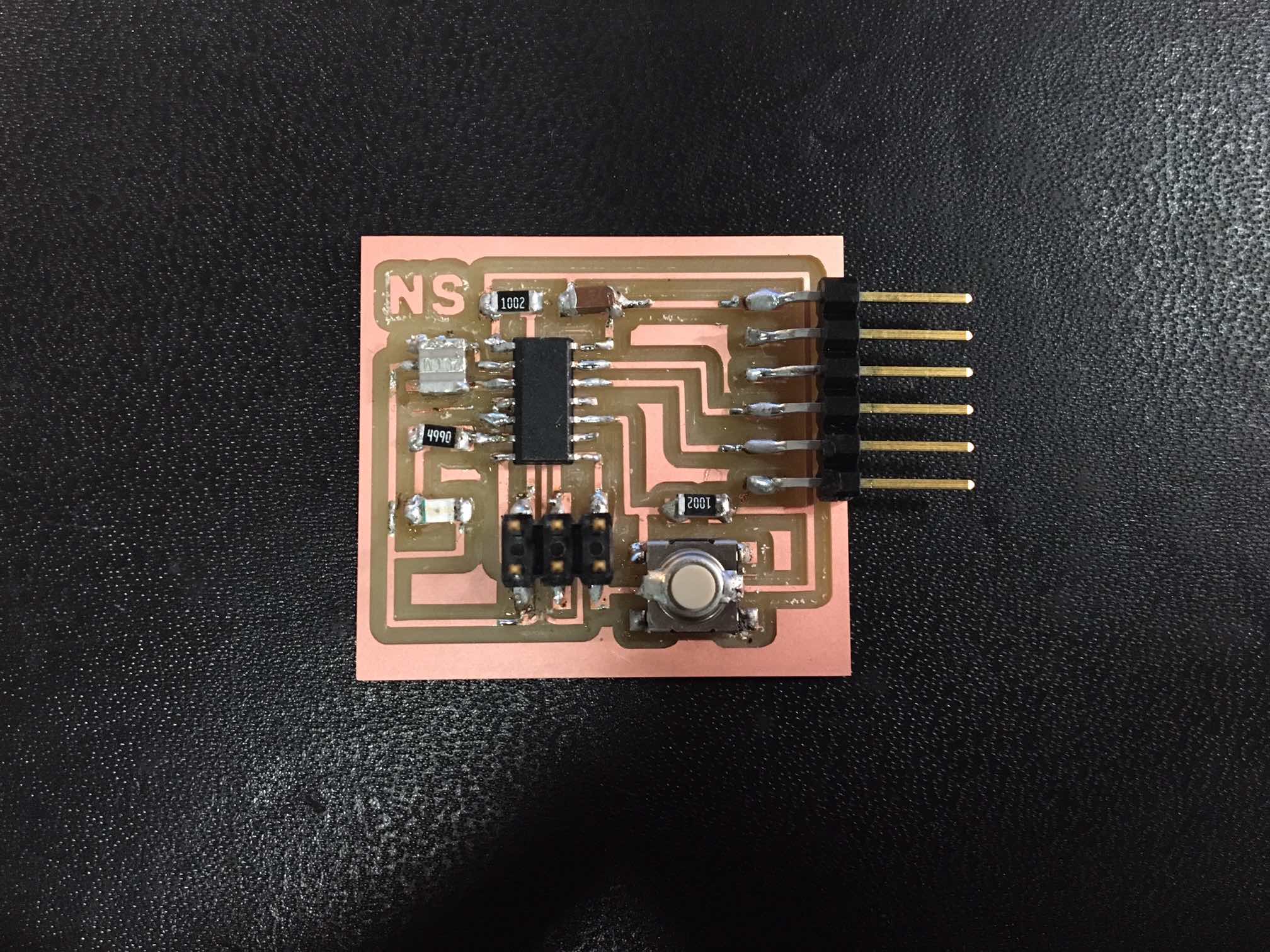
final board