
Week 6: Embedded Programming
Assignment: Program the board from two weeks ago.
This week was a bit of a disaster for me. I think almost everything I thought could go wrong with the board went wrong. Downside was I spent a ridiculous number of hours trying to debug. Plus side is I know now a lot more about electronics than a week ago.
Fail Attempt #1
I started optimistically trying to program the board I had designed in Eagle a couple weeks ago. I had never done any electronics before so I guess I did not check my old board very well. First, I attached the programmer and kept getting an orange light. I spent a bunch of time re-soldering and checking connections with a multimeter and kept trying again. Nothing worked. A couple hours into the process I realized a small trace between the button and GND was missing so the button wasn’t really connected to much. Whoops. (see button of picture on the right). Time to go back to the drawing board.
Fail Attempt #2
I opened up my schematic and board files in Eagle only to find that for some reason they were inconsistent and therefore had no back or forward annotation. After working with Randi and a scouring Google to find a way to reconnect them and trying a ton of different things, I kept having the same issues. For some reason the button connections were not like they were meant to be in the schematic. The schematic was perfectly fine but I couldn’t get the traces to get fixed. It kept showing S$1 for the connection between the bottom two pads rather than GND.

Finally, I gave up and decided to just remake it in Eagle. I figured the practice wouldn’t hurt given my limited experience. Remaking the board didn’t take much time this time. I even tried out curving the traces for fun. I ended up with the design on the right. Thank god!
Failed Attempt #3
Well, thankfully I was making progress. At least the design was good to go. Gimp and I struggled for about an hour to get the images to work correctly. I finally exported the new images and started to mill. But, my excitement was short lived since I saw the milling was scaled to double. I forgot this stupid issue with Gimp on Retina Macs so went back to scale the images down to 50%. I decided to make two boards just to be safe. Which was smart since I totally ended up ripping the traces off one of them.


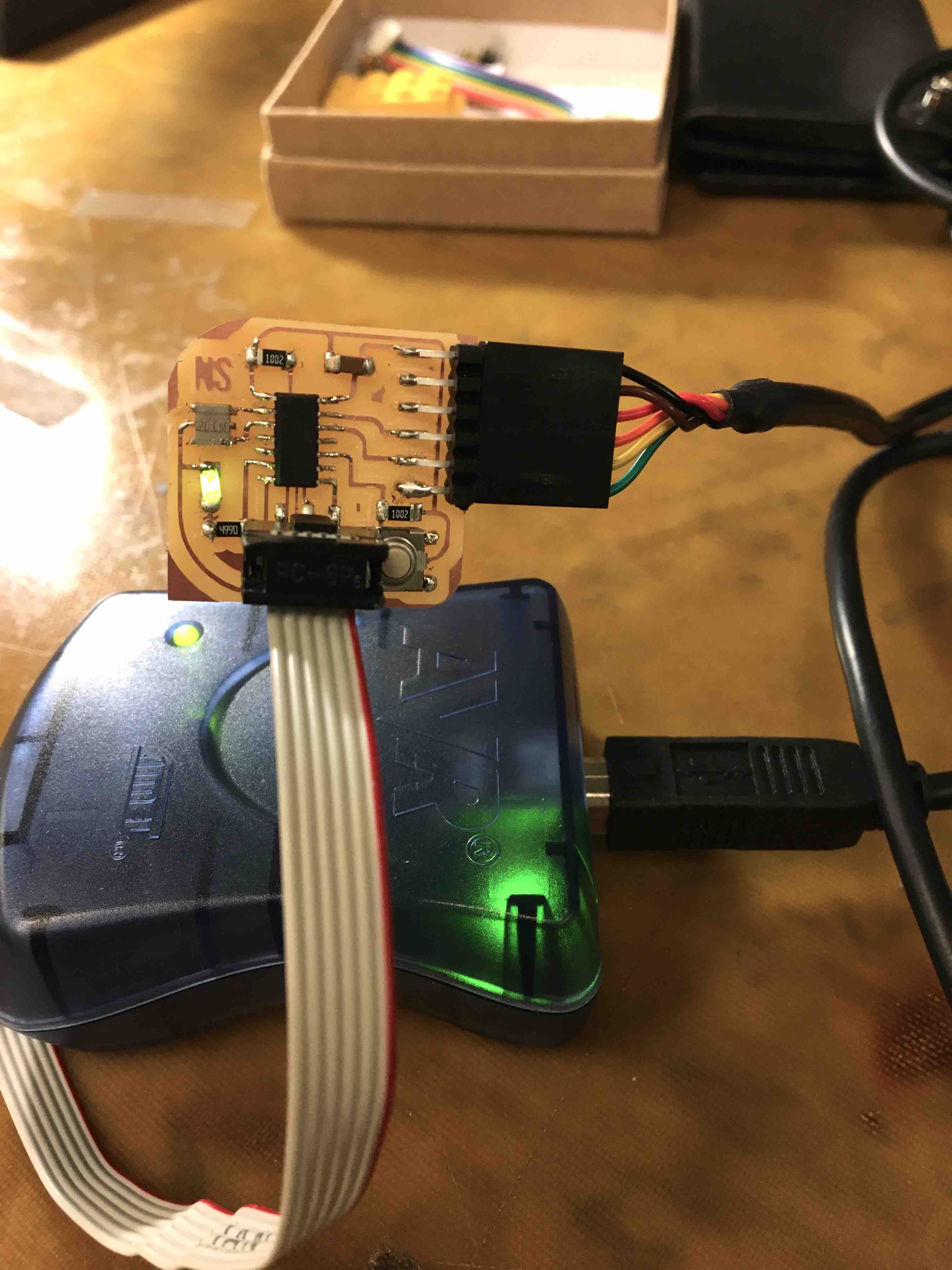
Finally, it works!
Finally, I got the new board soldered (which was surprisingly fast!). Then I couldn’t get the LED to light up. I realized I had it backwards (yay diodes!). I still get messed up about which direction to place LEDs. Anyway, I desoldered and it put it back in the opposite direction. Then I tried to program. The program loaded just fine but failed at turning the LED on. At this point I used the multimeter to check all my connections. I realized that I used the numbers from the schematic rather than the pin number following the PA to identify which pin the LED and button were on. I edited the code and it worked!
I decided to keep my iterations of the program simple mostly because at this point, I was about ready to be done with this project. I programmed it to turn on and off with the switch using the Arduino IDE. Video below!
-
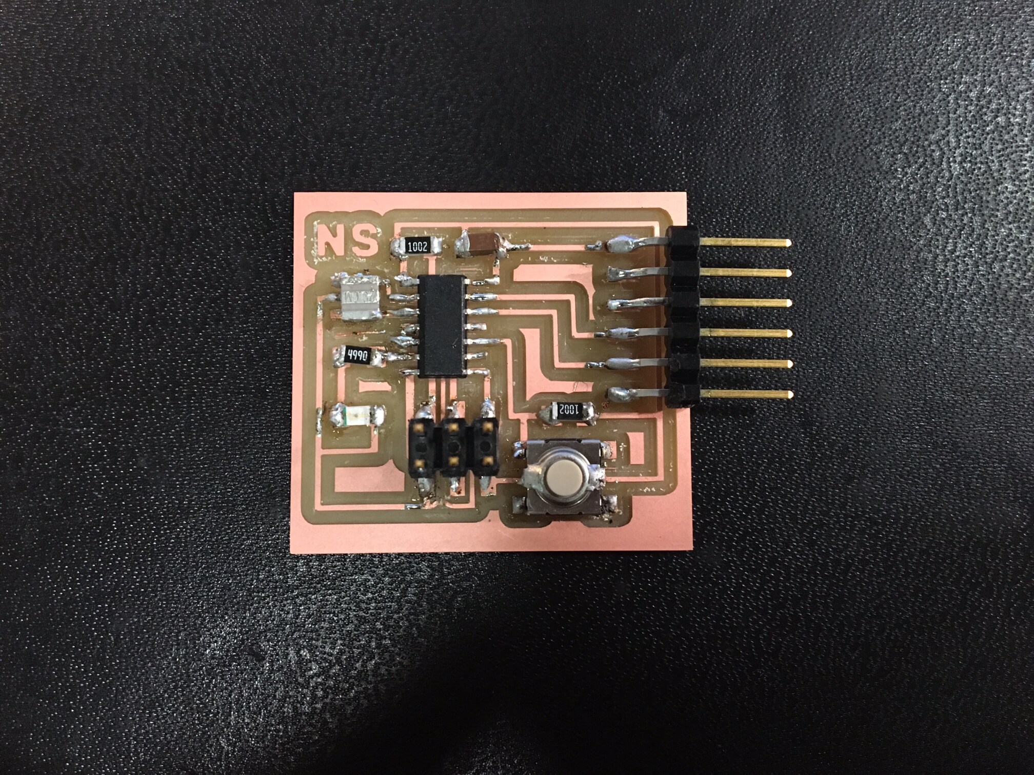
failed board 1
-
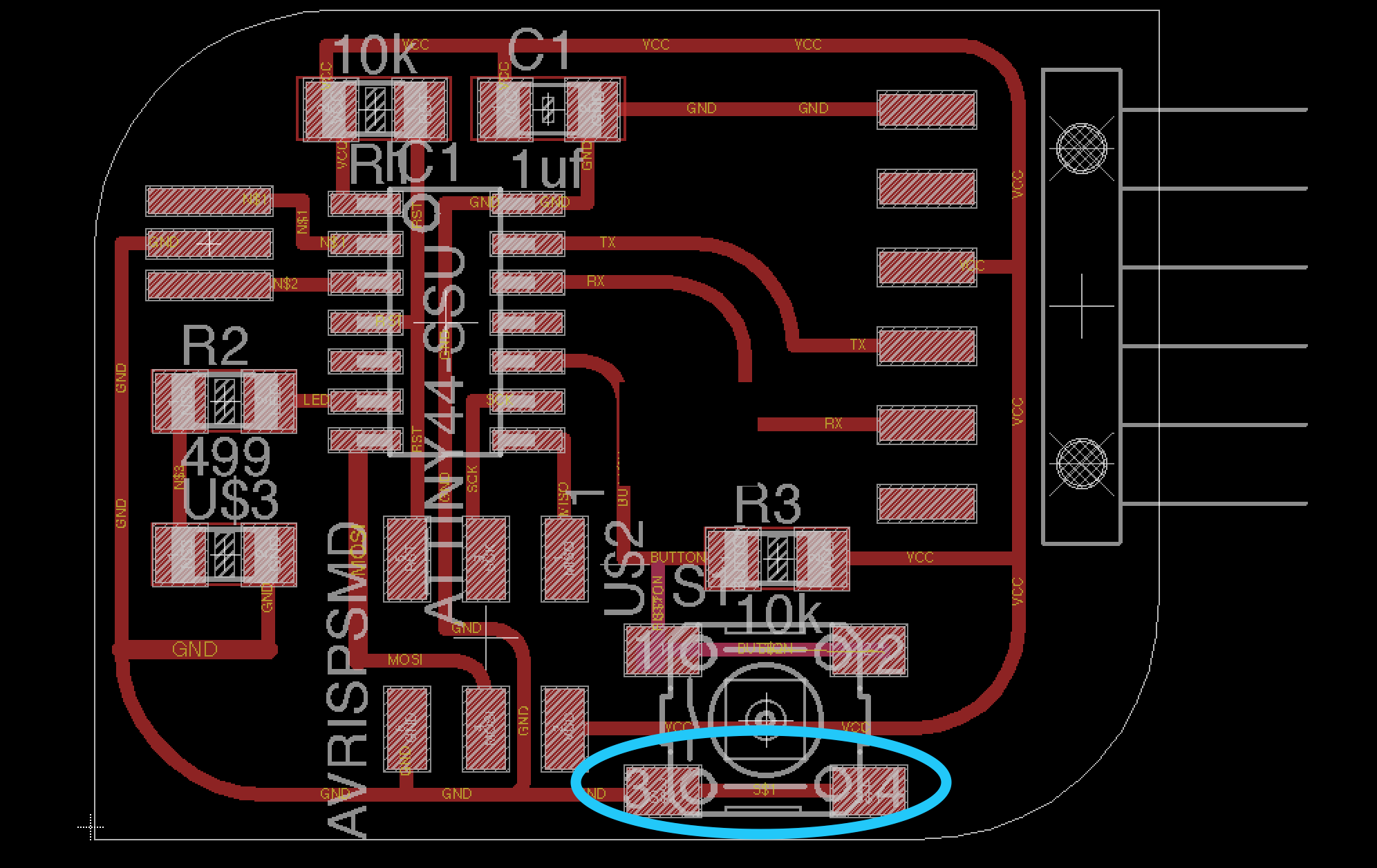
error in attempt 2
-
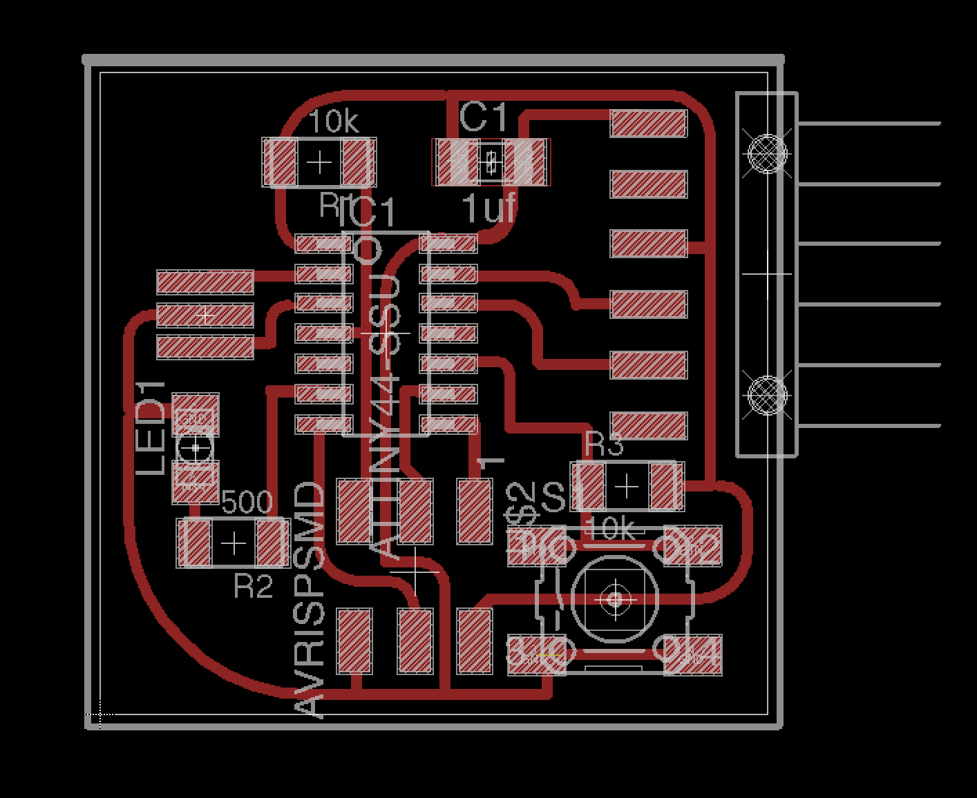
finished board routing
-
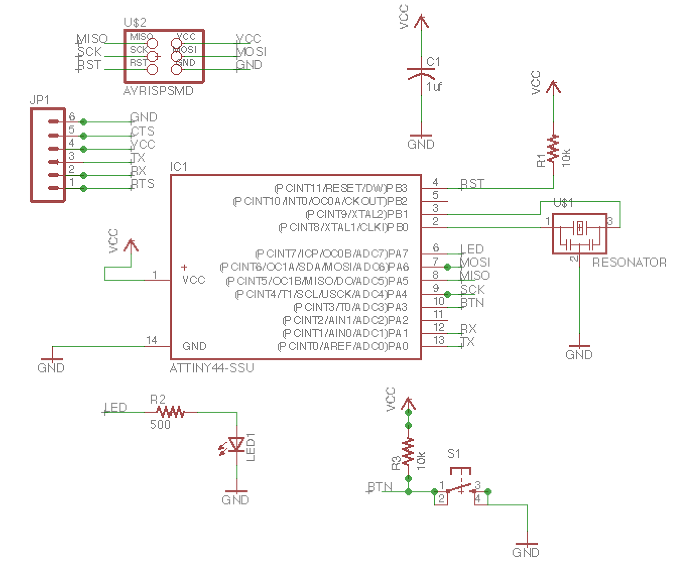
finished schematic
-
it lights up!