Week nine: input devices
When it saw the world...
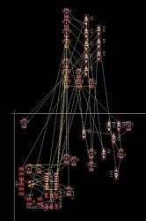
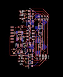
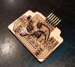
This week our assignment was to design and program a board with an input sensor. I decided to design a joystick for my future robot with two inputs for each arm and a button to switch the face.
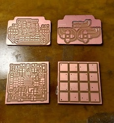
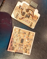
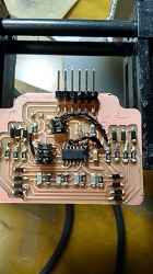
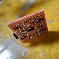
As of right now, my board does not work. I will work on it more after class. With one board I ran into problems stuffing it. It seems that I incorrectly soldered the resonator such that XTAL2 and GND were touching. So I could program the fuses, but after that nothing worked since the board was relying on the clock. When I tried to desolder the resonator I basically melted my entire board. On the other board I ran into problems programming it. I remade Matt Keeter's multitouch input board, thinking that I could use it as a backup since it was physically very similar to what I wanted. However, Matt Keeter's board has no ISP header and I had no idea how to program it.
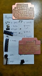
When I remake the board, I think that I will use fewer jumpers and try to route for 0 ohm resistors instead. They are a lot easier to deal with. They also won't melt if I need to remove a piece from the board.
I connected the two sides of the board by using thin, short pieces of wire and soldering the tips to the pads. I used coated wire so only the tips were exposed. I cut them so that they perfectly matched the height of the two boards taped together back-to-back. Doing this took as much time as soldering the rest of the board. It required a lot of debuging of the joints.