Final Project
A Physical Brain Map
Dec 14, 2016
Motivation
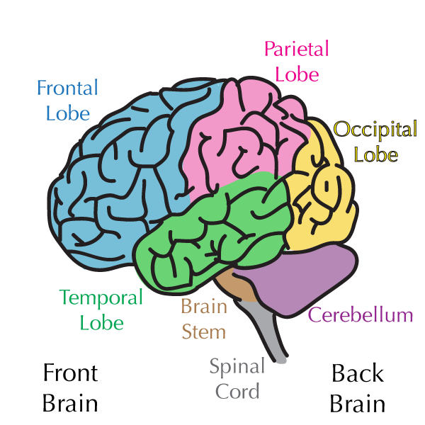
My original idea for this project was to make a 3D model of the brain to show spatial patterns based on fMRI images of brain. As Neil always says, in the spririt of spiral design, I decided to scale down my project and instead make a physical 3D map of five major brain regions:
- Frontal lobe
- Parietal lobe
- Occipotal Lobe
- Temporal Lobe
- Cerebellum
When you touch a part of the brain, the corresponsing region lights up and you can learn more about the functionality of that region on a computer. Good project for a science museum!
Harry McNamra's brain project
A previous student, Harry McNamra, had done a similar project, interactive brain. His brain has pressure sensing via step response of plates embedded in silicon rubber and outputs light or audio when it is poked or squeezed. His workflow was to 1. 3D print the brain 2. Create a 2-part oomoo mold for re-casting 3. Re-cast the brain in MoldStar silicone (with internal components)
What I'm doing differently is that I'm splitting the brain into 4 subregions and assembling them like a puzzle. I'm also making an interface with Tkinter to show descriptions about the region that is touched. My model doesn't have an audio output. I used my own designs for both electronics and 3D modeling.
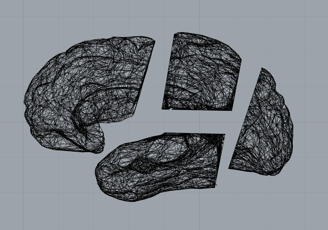
Splitting the mesh into pieces
I found a stl mesh of a human brain model on clara.io. I used Rhino's MeshSplit command to divide the model into 5 regions. But playing with the mesh turned out to be quite hard! I ran the command... nothing happened! I ran the Check command to see if there was anything wrong with the mesh, and there was.
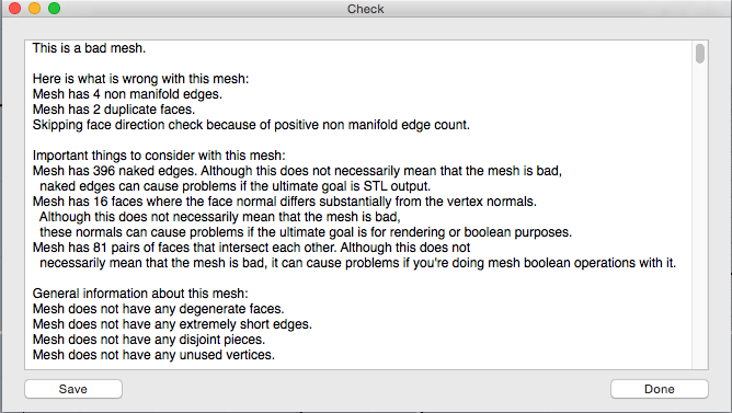
Apparently on Window's version of Rhino, you can see nonmanifold edges, but since the Mac version is new, I couldn't find this command. Instead, I used ReduceMesh to simplify the mesh, and that did the magic.
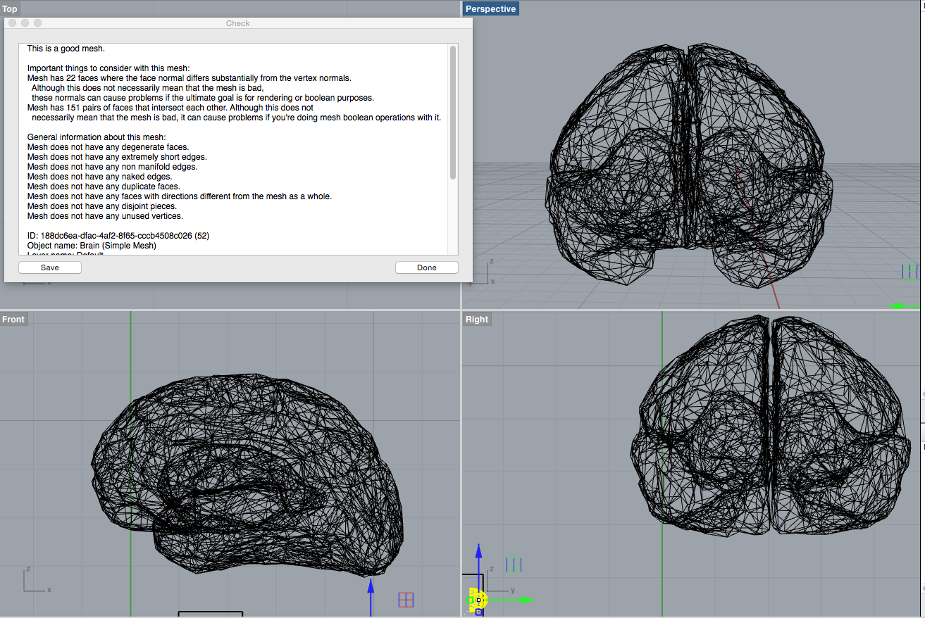
But I wasn't quite done yet! Now when MeshSplit only split a layer of mesh from the object but left the rest intact. After a long time of struggling Rhino, I finally realized that the I had to flip the normals of the cutting object.
Last thing was to fill the holes that were created by splitting. I used FillMeshHoles command for this. There were still some naked edges left which I manually removed from the mesh. I also decided to not include the 5th region (cerbellum), which is positioned right beneath all other parts, to simplify molding and casting. I also made the internal faces of the parts flat so that I could make a one piece mold, with the flat face facing out.
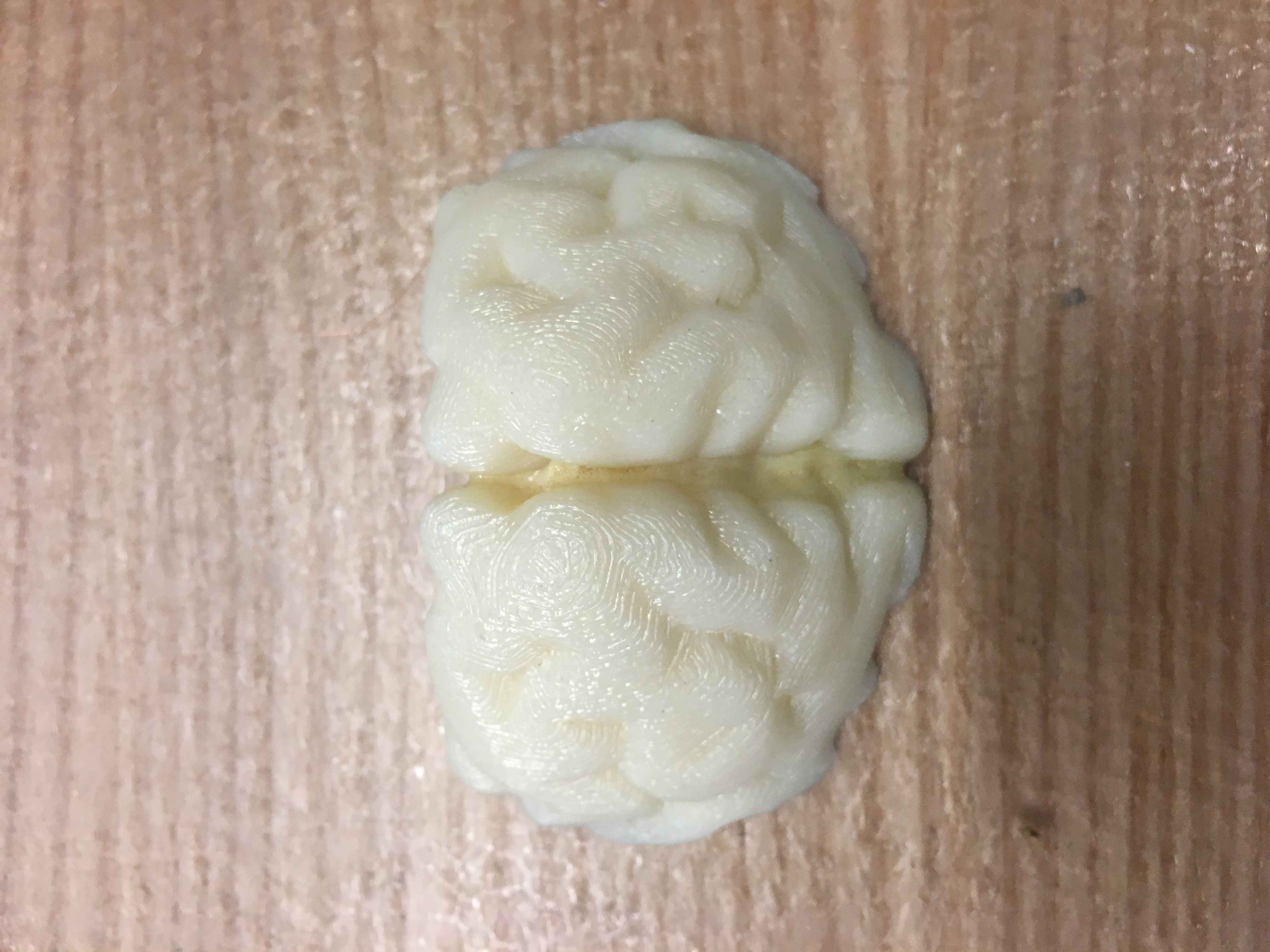
There it is, brain in 4 pieces and ready for 3D printing!
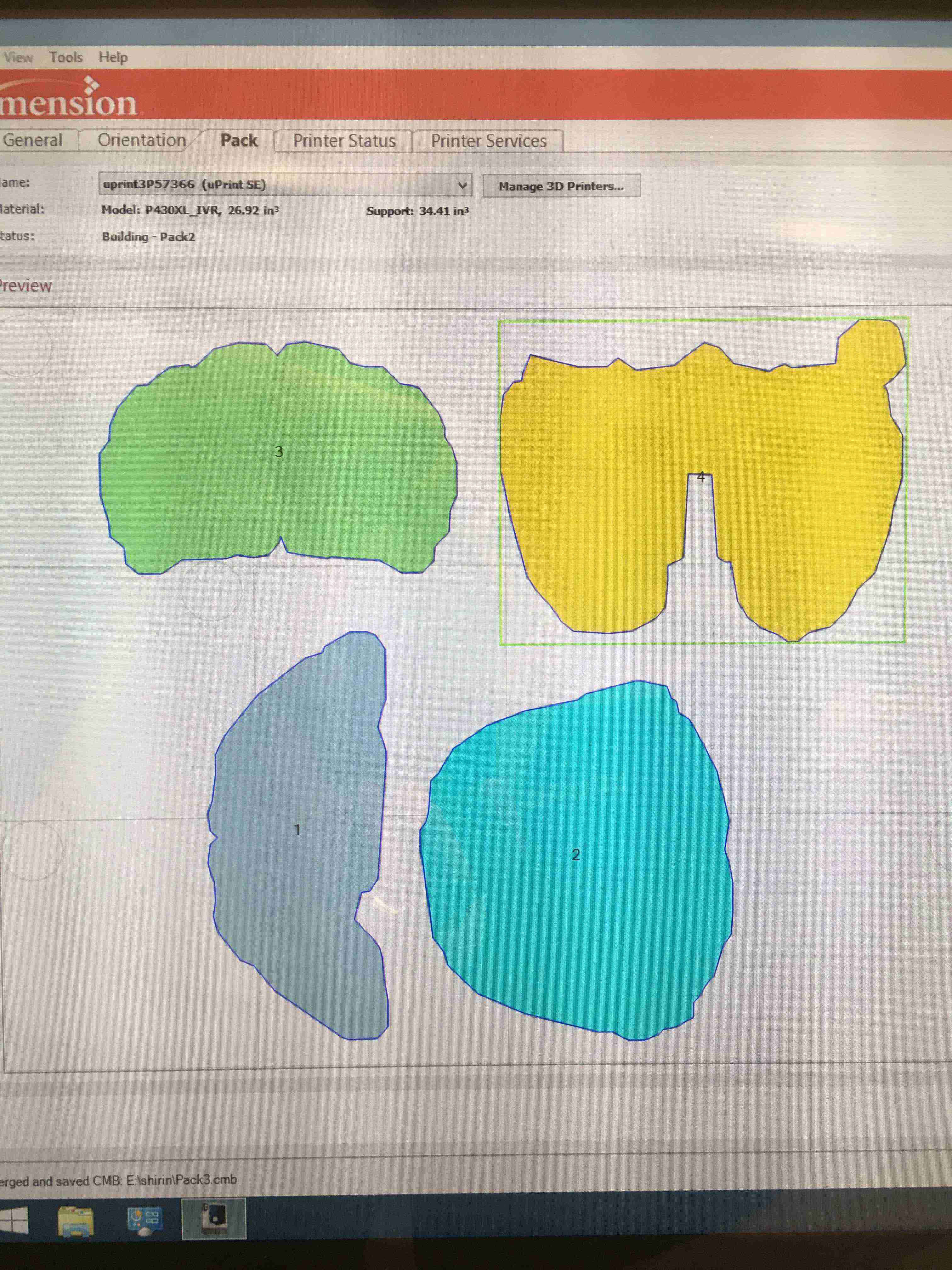
Molding and casting parts
It turned out that because I had divided the brain into 4 regions and had to print each separately, the total printing time was very long. I tried ptinting only two of the pieces and the estimated time was 20 hours! Nobody has that much time, and I couldn't occupy the printer all for my own! So I scaled down the pieces by 0.6. Now it's more like a cat brain than a human brain, but the total printing time for all pieces was about 14 hours. I also noticed that one of the pieces was asymmetrical and was missing a small part. In the interest of time, I decided to leave it as it were, but this would me something to edit next time.
Unfortunately, after dissolving the support material, some of the prints came out in smaller pieces, and there were also a few empty sections in the brain. I think it must have been becuase of my mesh.
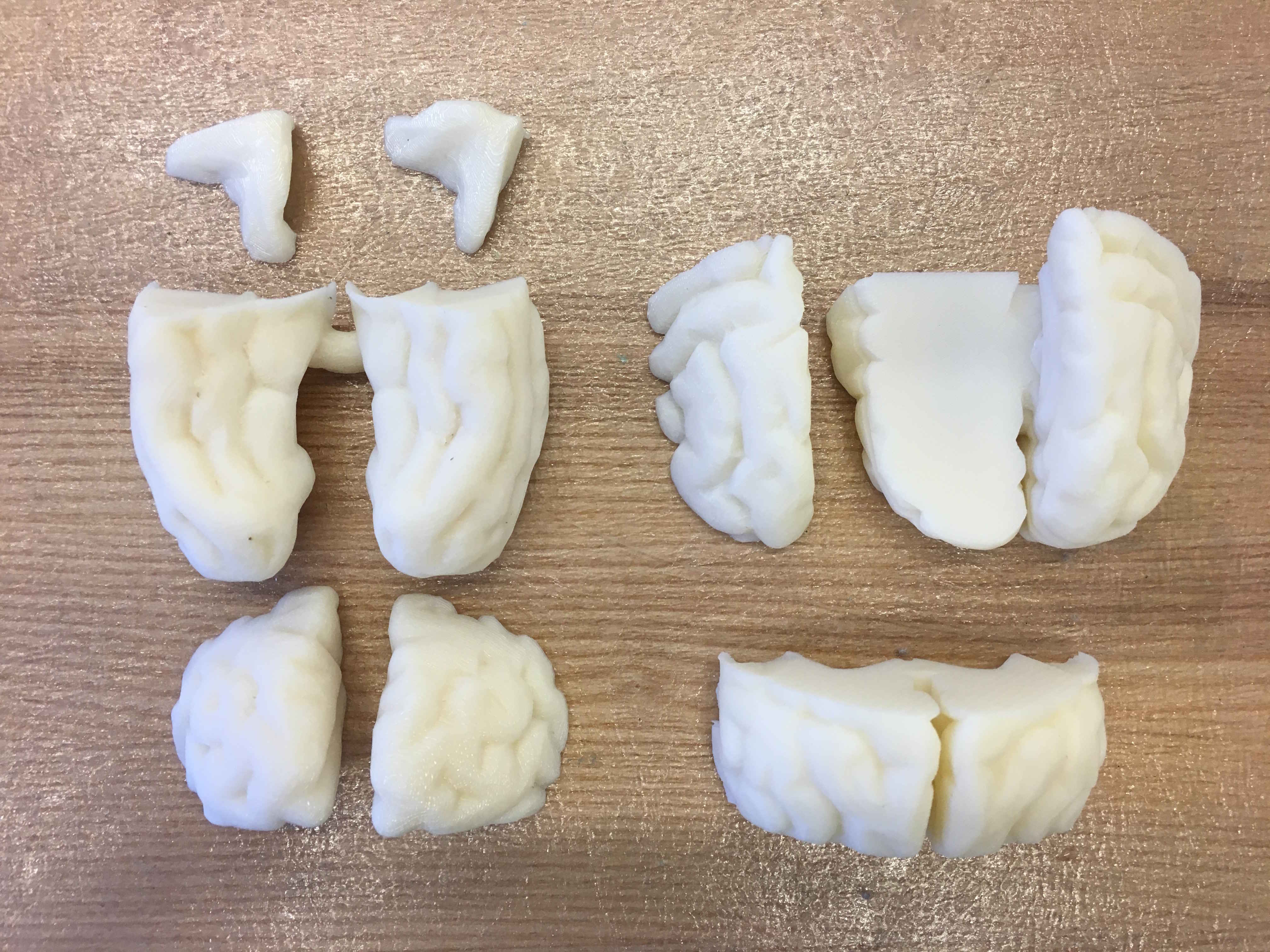
Since I didn't want to run another printing job, I tried to fill in the empty spaces with Gorilla Glue. It turned out very well for some of the pieces. You need to make sure to dampen one surface and apply glue to the other surface and then clamp them together. It turns out to something spongy.
But it wasn't possible to fill in the hollow sections with it. I poured in glue from one side and it came out from the other side. Instead, I wanted to used tape to cover the holes, but I wasn't sure if oomoo and tape would react. So I borrowed some oomoo from Tuan who was making a mold for himself, and made a test sample. It worked fine! So I covered the rest of the holes with tape.
I made small containers out of cardboard box to pour oomoo in and make molds.
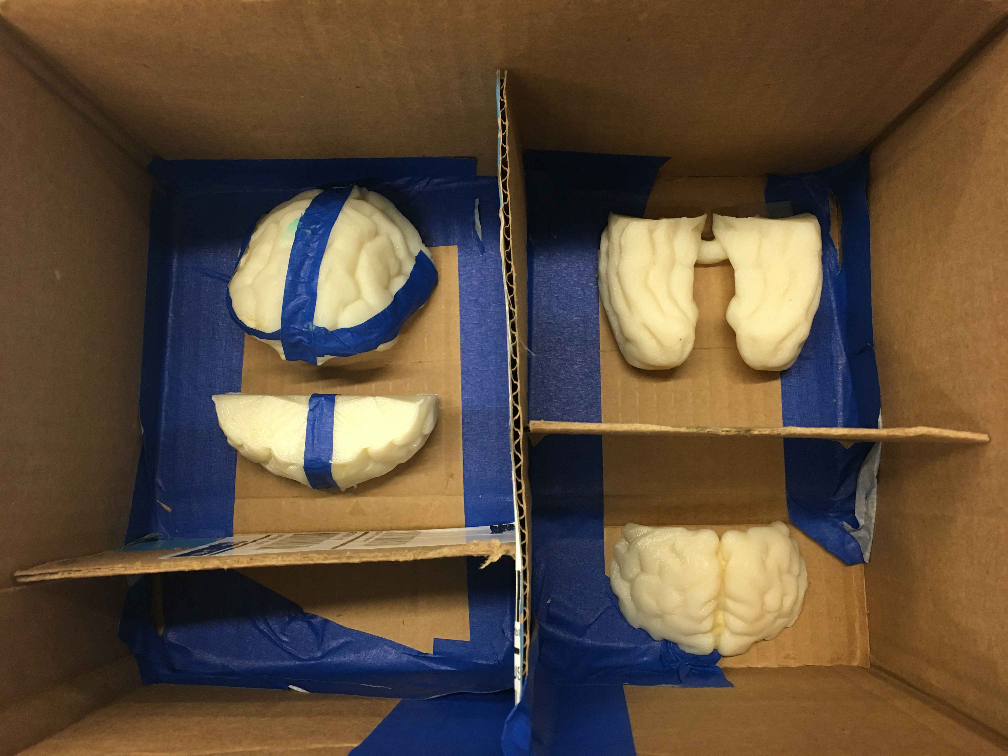
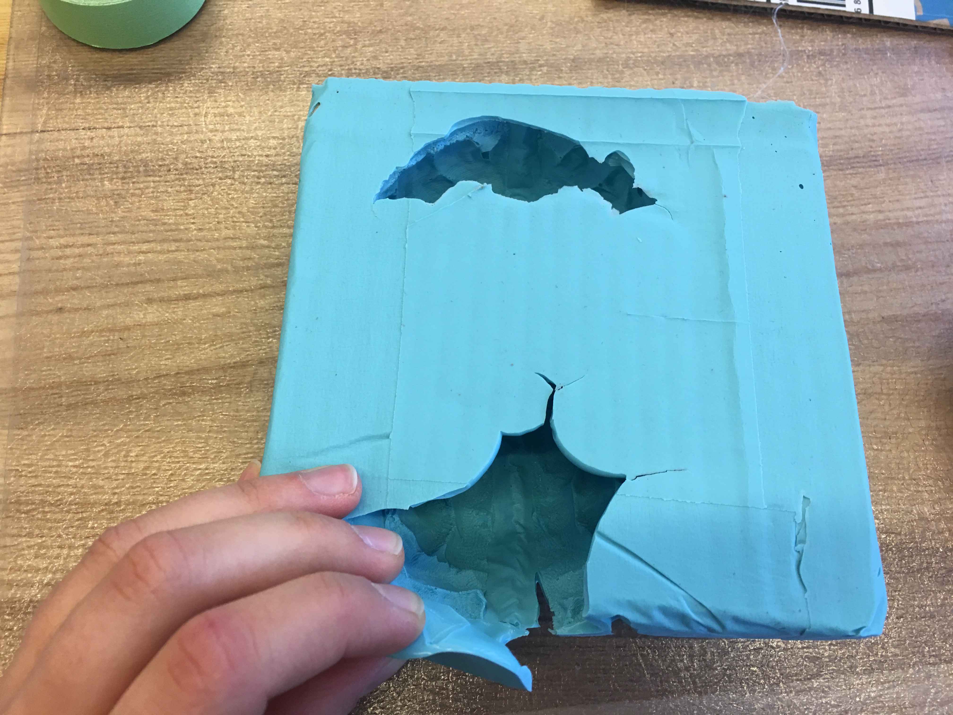
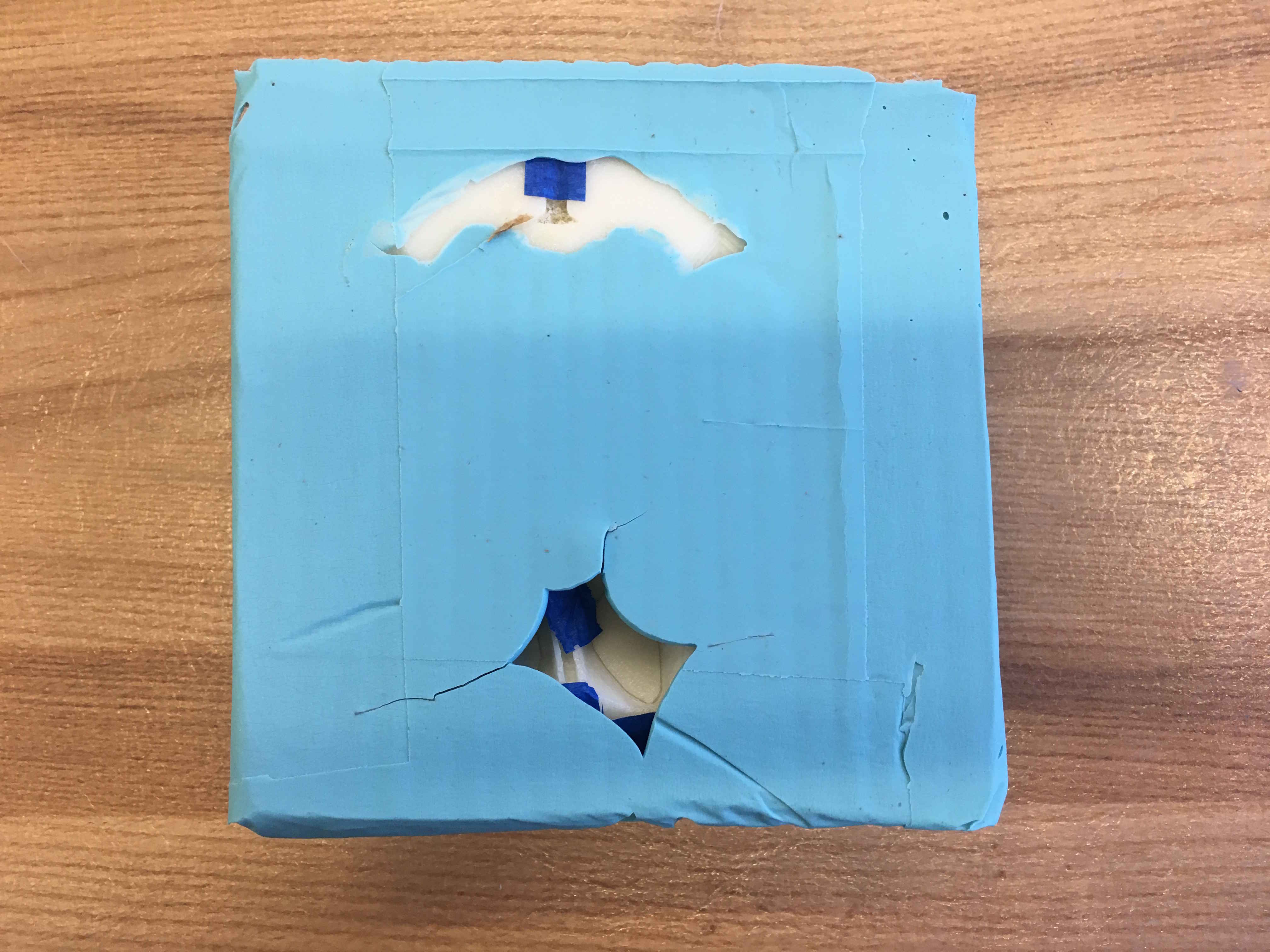
The first time I tried making molds, it got messed up a little. I made a mistake and mixed huge amounts of oomoo which meant more mixing. By the time I was pouring oomoo on my third and fourth piece, it started curing. Some of the pieces had hollow curved structures and it was hard to get oomoo into them. Also oomoo had gotten under the pieces, but it was easy to cut the cured oomoo and takes my pieces out.
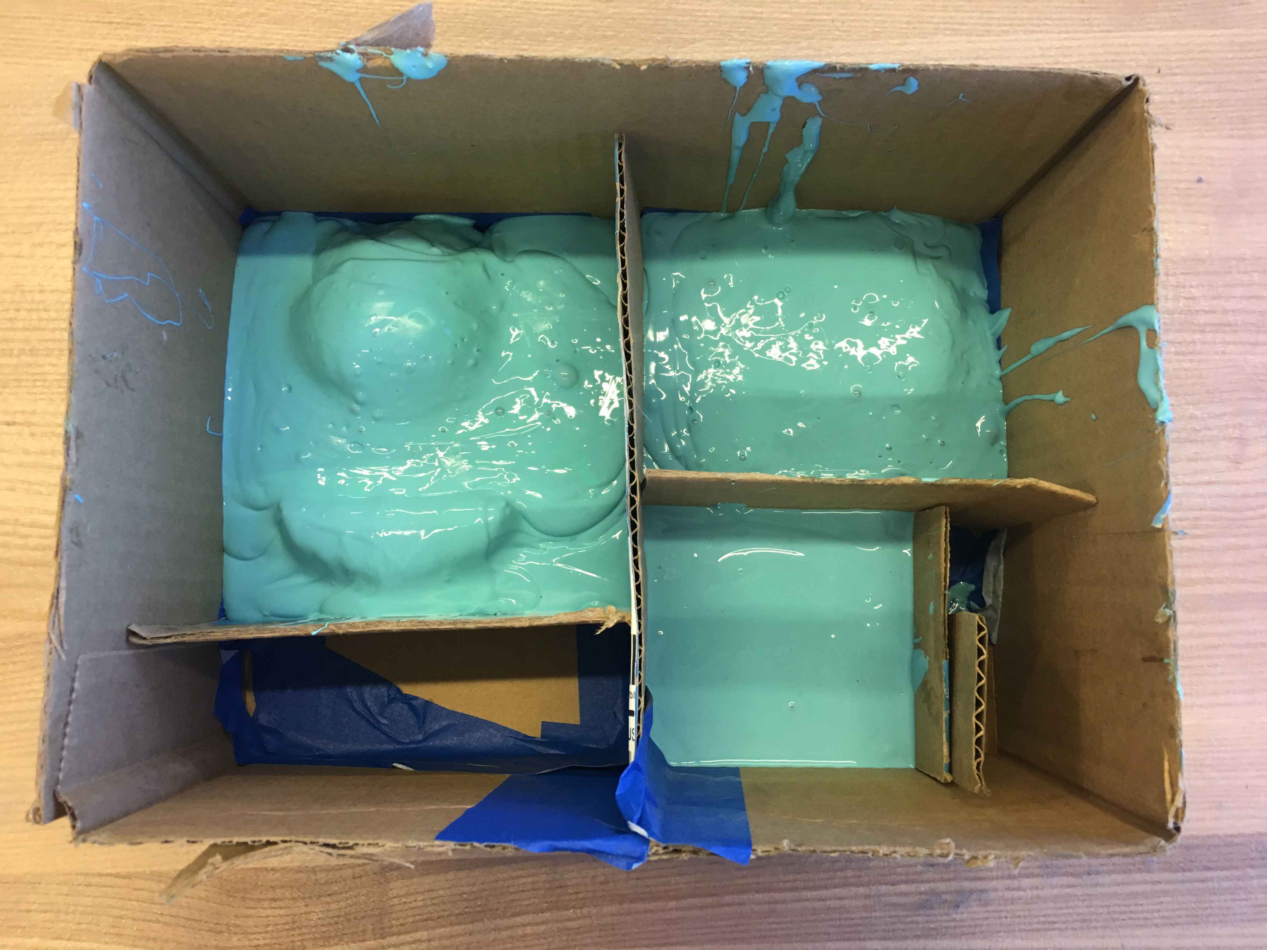
I gave it another shot with more caution this time, and it worked much better. I also made smaller containers for them so that I could prepare oomoo in smaller batches.
But a problem this time was that the pieces moved up to the surface as I was pouring oomoo. So the entire surface was covered with oomoo but it was very thin on one side.
To make the final pieces, I was first going to use Sorta-clear. Then I realized its cure time is 4 hours and it actually was too transparent for what I wanted, because I didn't want the circuits to show. With some search and inspiration from Harry's previous brain work, I realized that I could instead use Moldstar 20T. It's a liquid rubber with a 30 min cure time and it's translusent. But of course we didn't have it in the inventory. I had to take a last minute trip to Reynold's to get them. It was actually a fun trip! I've been hearing about Reynold's from Neil and other students all semester.

I first made a sample to see what it looks like (and also embedded electrodes inside - see below for electronics). The pot life is 6 min so you have to mix and pour really fast, but it actually doesn't trap many bubbles, and even if it does, they don't show because it's cleat. It's also really easy to mix. The sample cured in about 30 min and looked great.
I casted my pieces with the electronics, once they were all ready and good to go. The first part I made was very sticky and not fully cured. Material datasheet didn't say anything about how to cure, except that heat will reduce shell life and cure time significantly. So I put it on the radiator, but that didn't help either. I thought maybe I didn't get the ratios of part A and part B right, so I just decided to make the rest of the pieces.
I even let them cure overnight, but they were still sticky and not completely cured in the morning. Conlusion? DO NOT USE MOLSTAR 20T WITH OOMOO! Oomoo has something in it that prevents Moldstar from curing. Looking back, I remember seeing in Harry's page that his brain also turned out to be gewy, but he didn't say why. Anyways, now the texture (and the smell) resembles a real brain!
Electronics
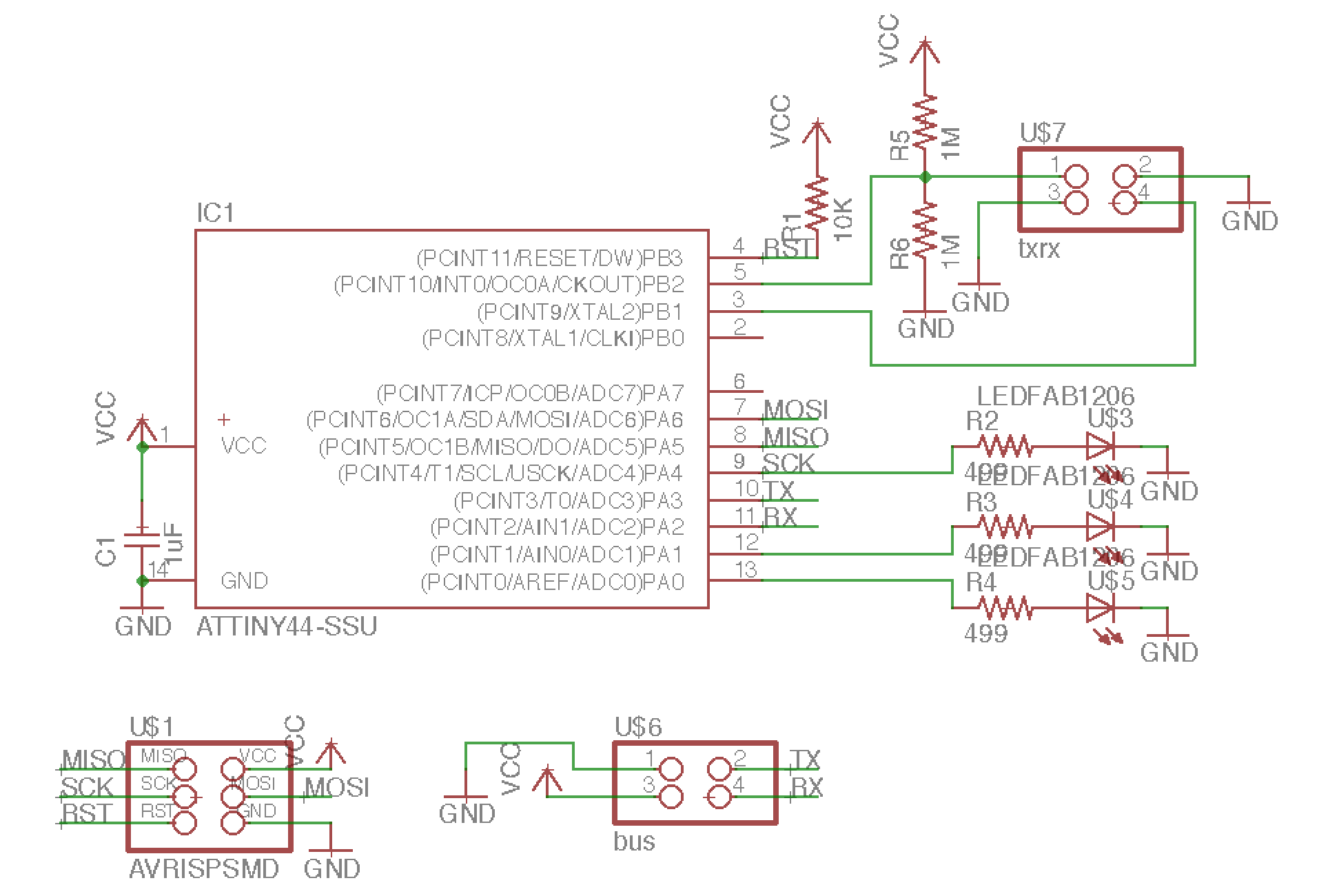
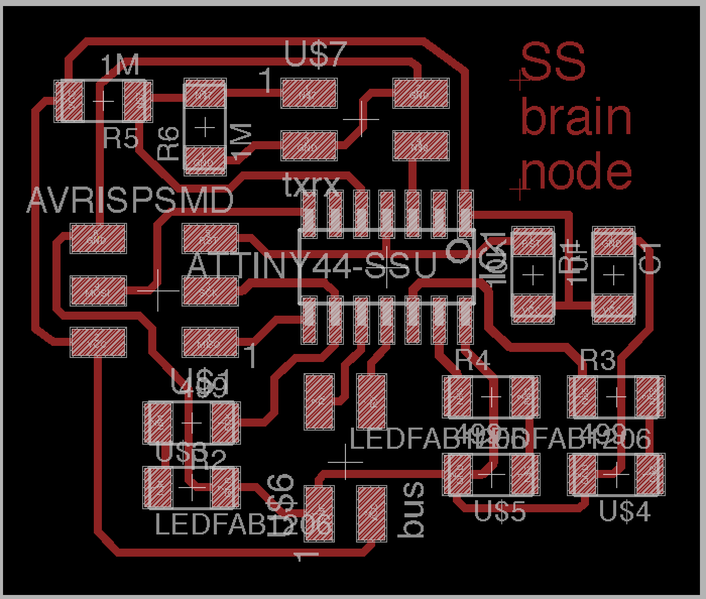
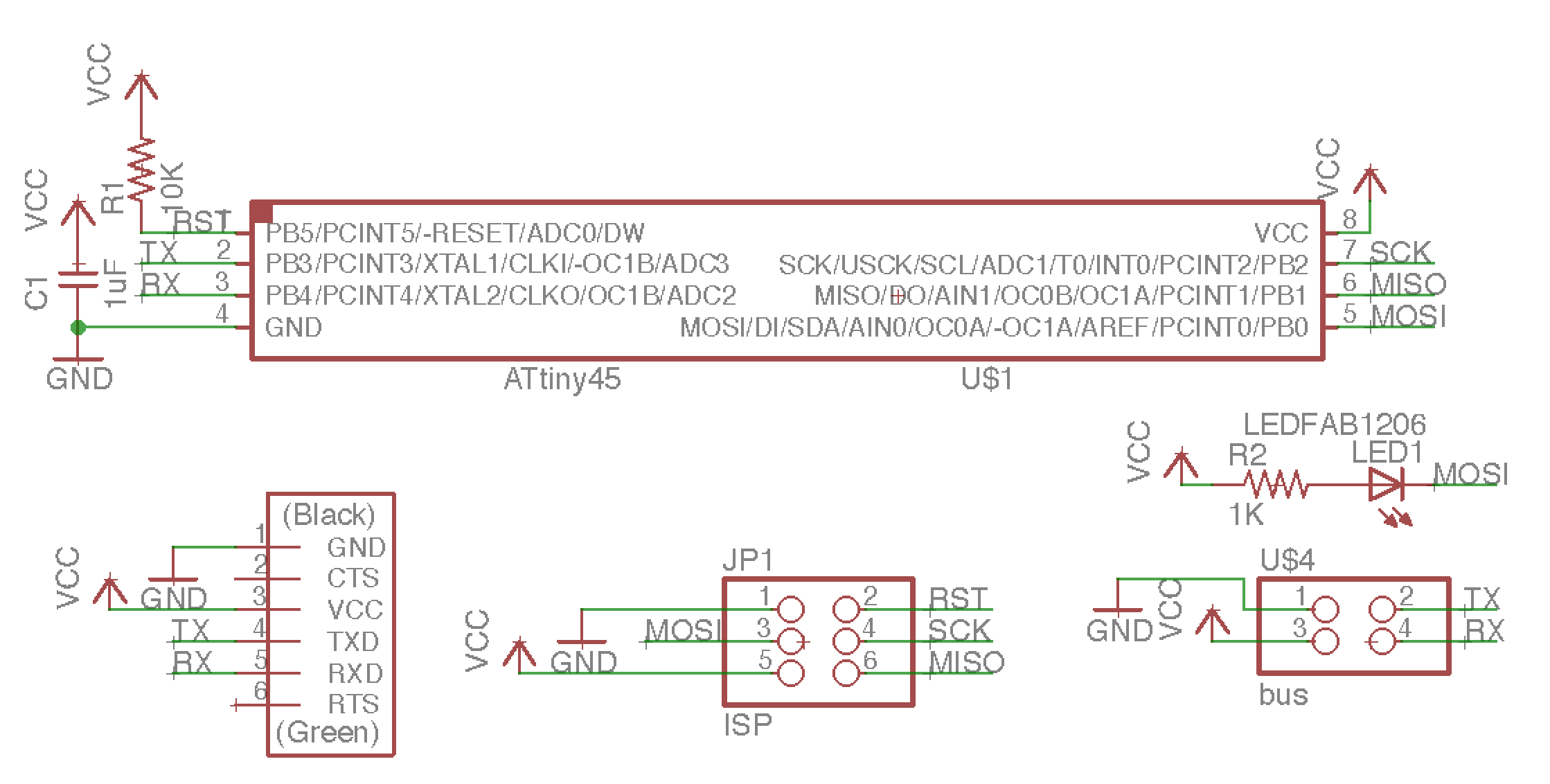
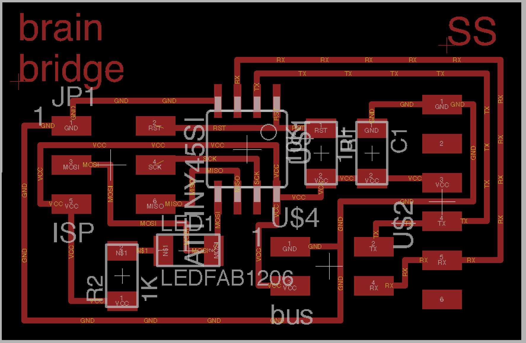
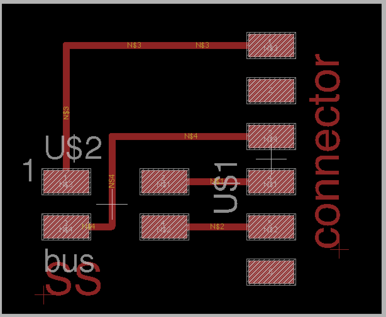
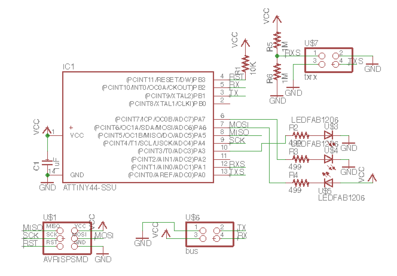
In the networking an communications week, I tried to connect my boards with the I2C prottocol. After to talking to one of the TAs, Will Langford, I realized that I didn't need I2C and I could just connect my boards with a rx-tx serial. So then I made a bridge board and 5 of the same node boards that will go in the brain. The bridge has attiny45, an LED to confirm it's being programmed, a bus header, and a ftdi cable to connect to computer. The nodes are the main boards that will go into the brain. They have attiny44, 3 LEDS, a step-response sensor, and a bus header.
First iteration: 5 nodes and 1 bridge board.
After talking to Will again, I realized that I don't even need the bridge board since it's not doing anything but connecting tx-rx serial pins to computer. So instead I replacesit with an adaptor board.
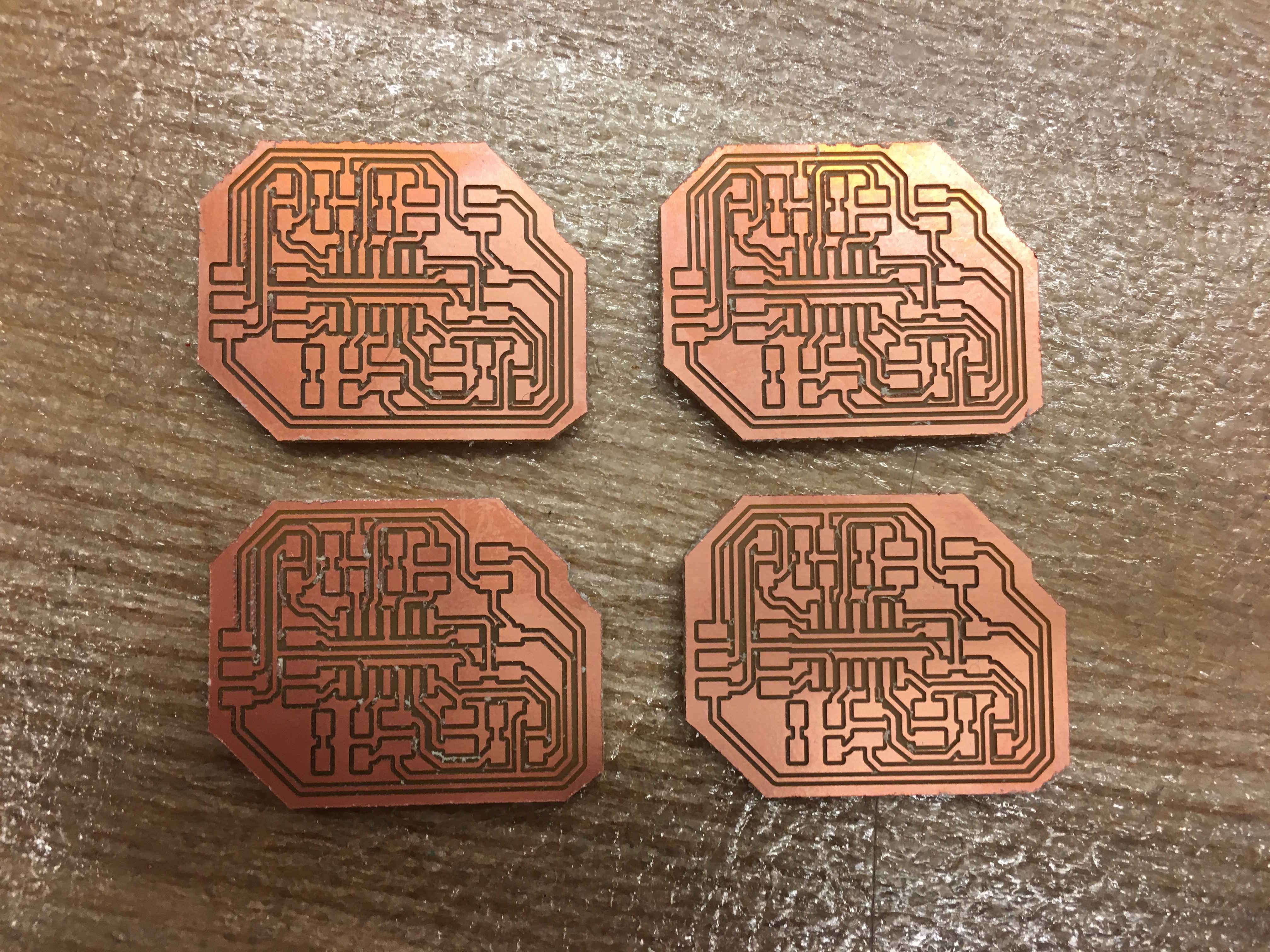
Second iteration: 5 nodes and an adpator baord.
After I made the board, the LEDs turned on, but not in response to the step response sensor. In fact, the board wasn't reading any data from the sensor. All it read was 0 or 1!
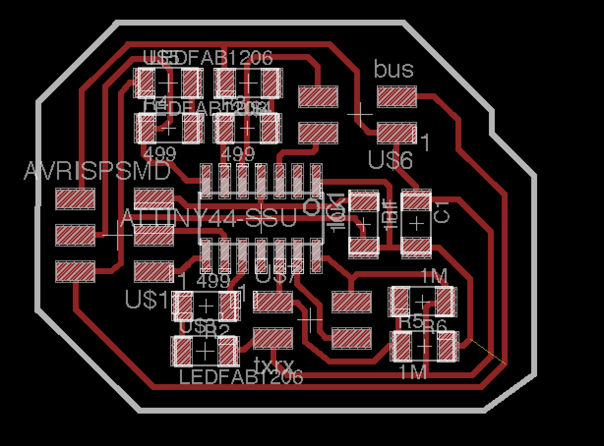
Wondering what I could have done wrong, I realized I'd made a simple mistake: the pins I used for step response sensor where on port B and weren't ADC pins. So I redesigned the board.
:::::::::::But now I couldn't program the boards! I kept getting the error: "initialization failed rc=1". I checked all connections, VCC, GND, and all SPI pins. VCC was at 5V, when connected to programmer. No shorts, everything connected well. I replaced the microcontroller, in case I burnt it somehow. Still didn't work. I decided to remake the board. The second board didn't program either. I even heated the board with a hot air gun to make sure all pads are well connected and the solder looks shiny. I was very confused what could possibly go wrong. So I decided to make a second board. All I did was to move two of the LEDS to a different pin and swapped the step response pins. No major change. Spoiler: these are my final designs.
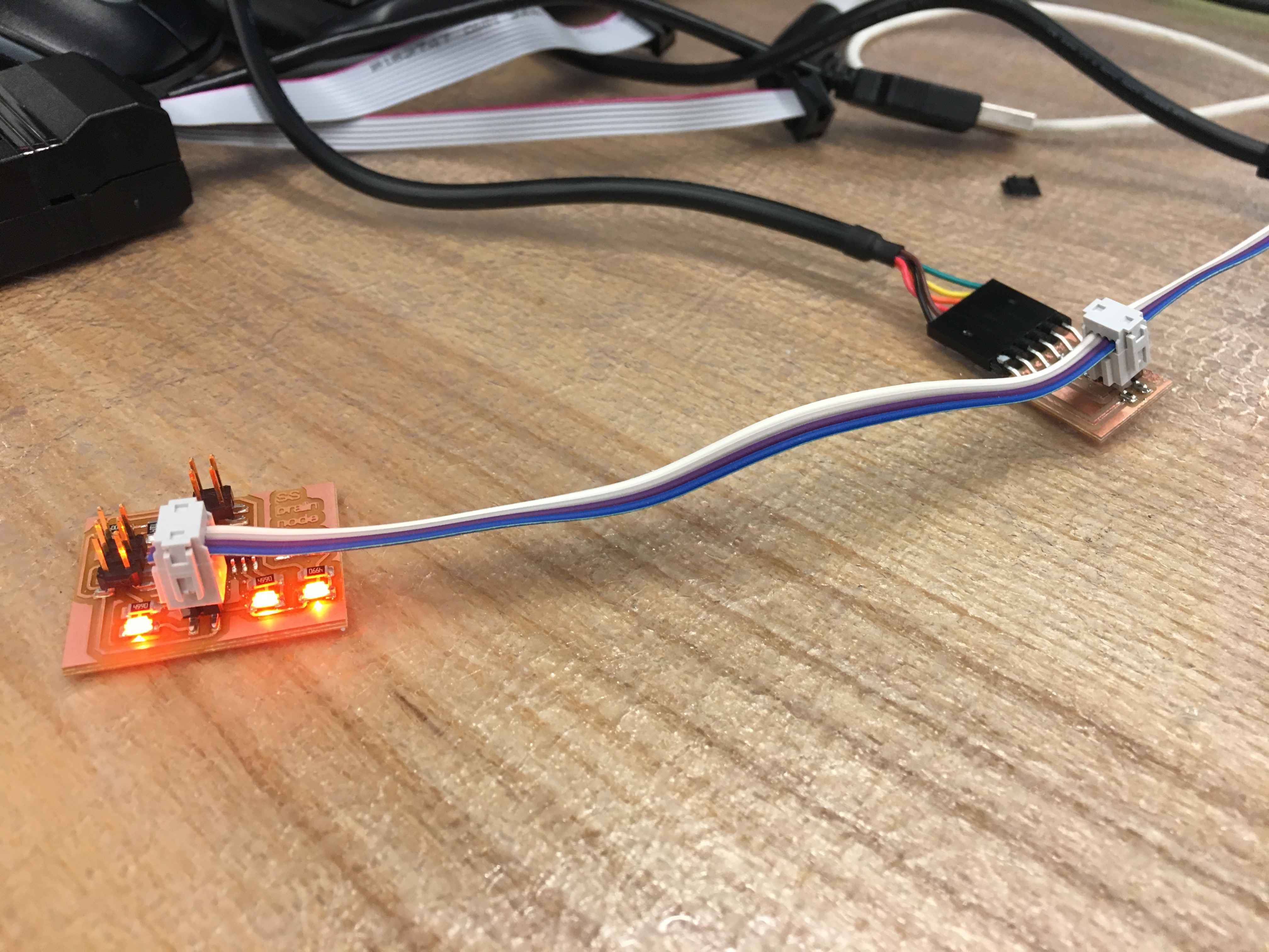
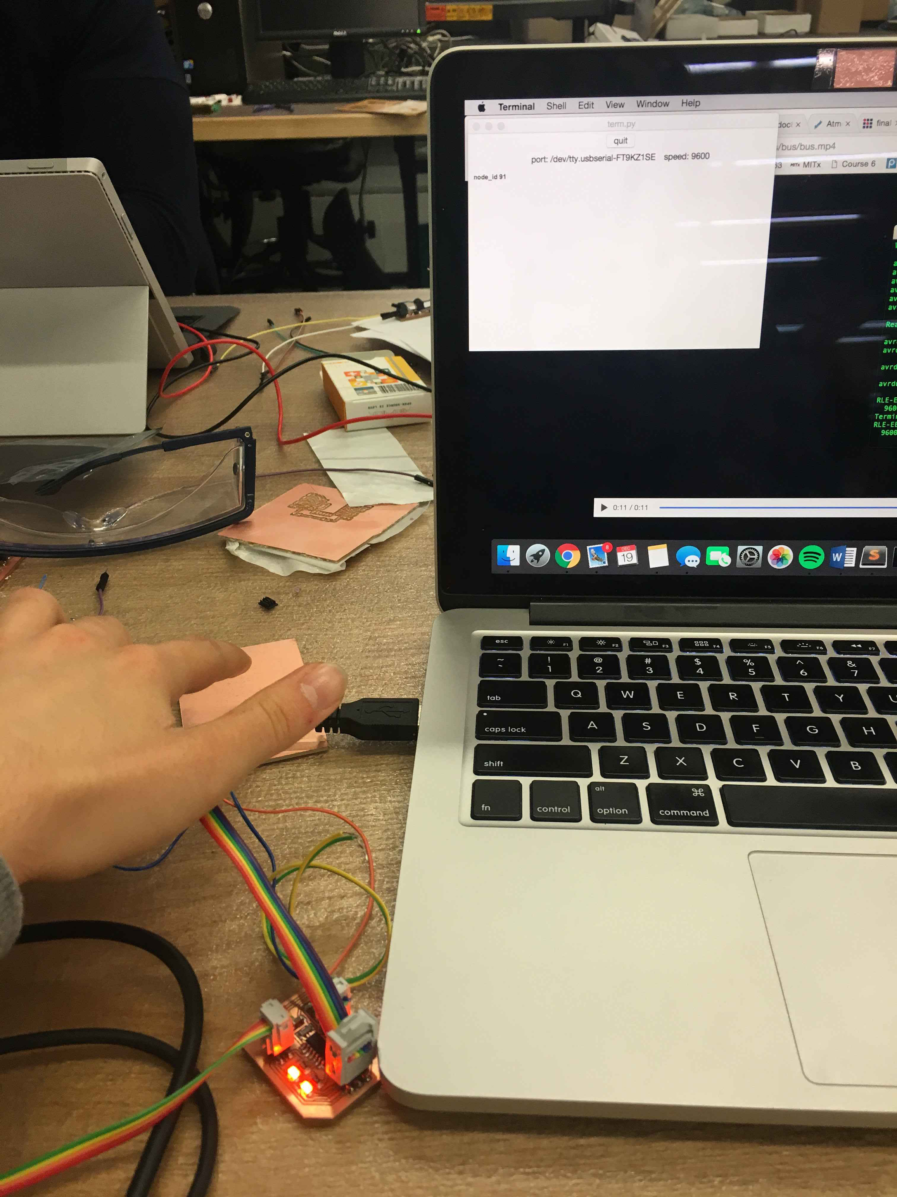
First few times of programmign didn't work... In all despair, I sat with one of my classmates, Anubhav, and we tried it together. Magic happened! The board sent its node_id as response to a change in the step response and turned LEDs on for 15 sec. I used Neil's term.py code to print and read data sent from the board.
Now I can move on! I made the 4 more boards exactly the same. I used the reflow oven to solder them.
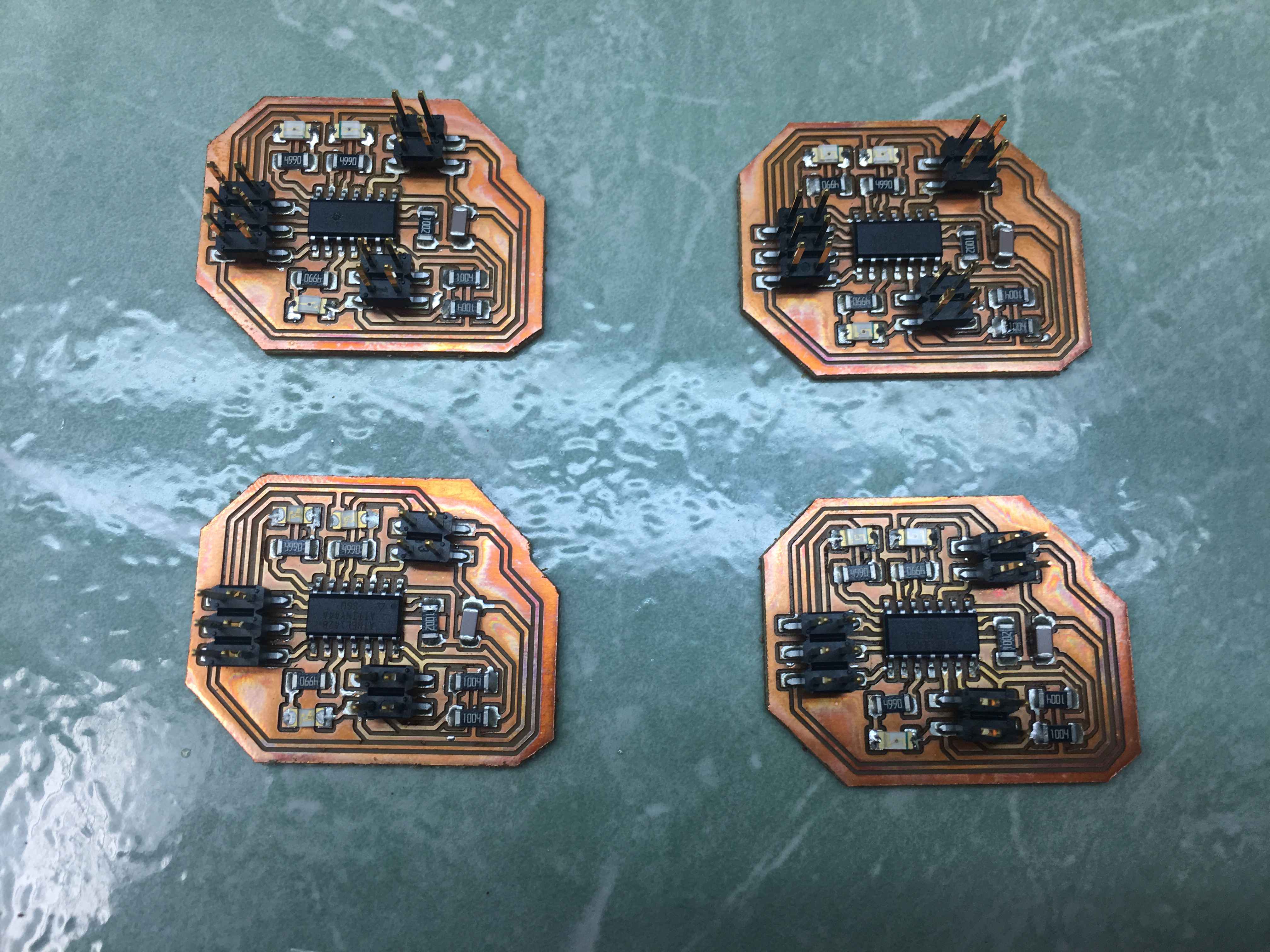
They all work perfectly!
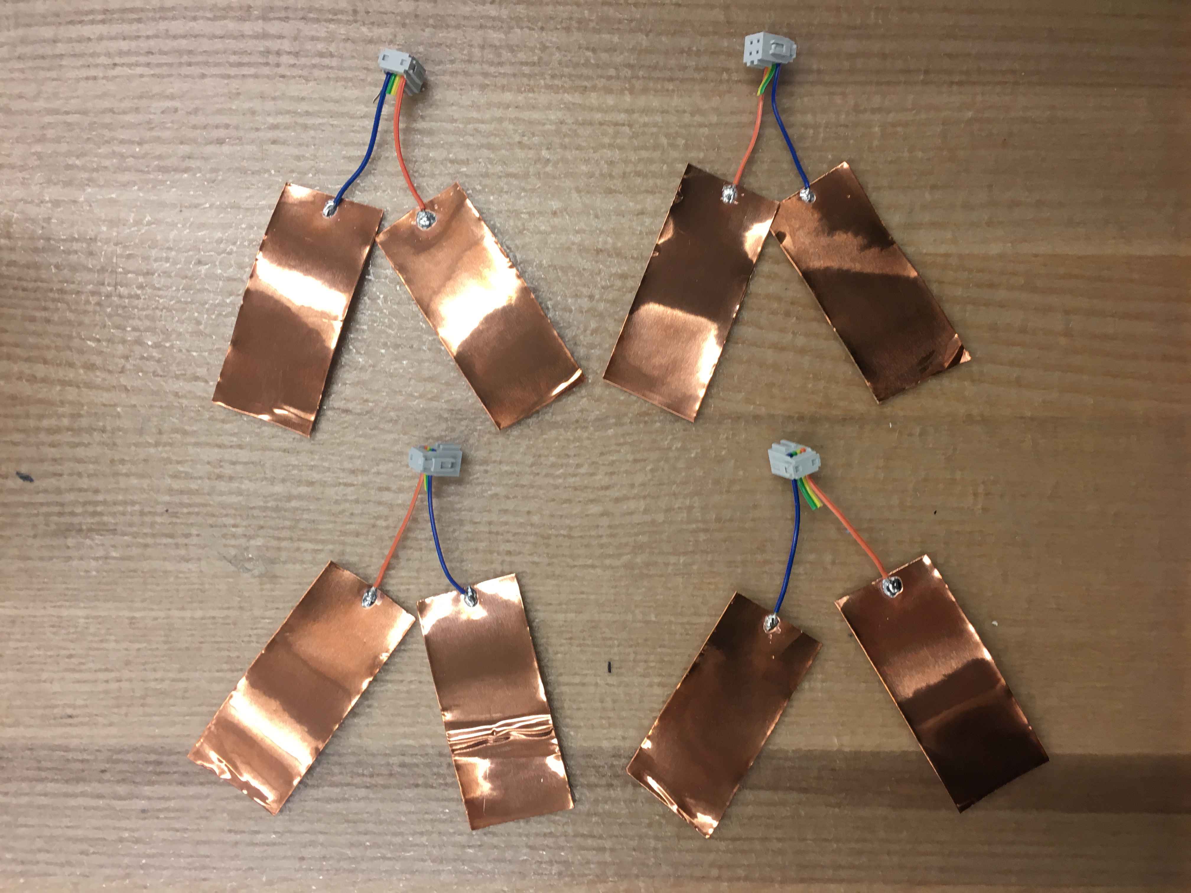
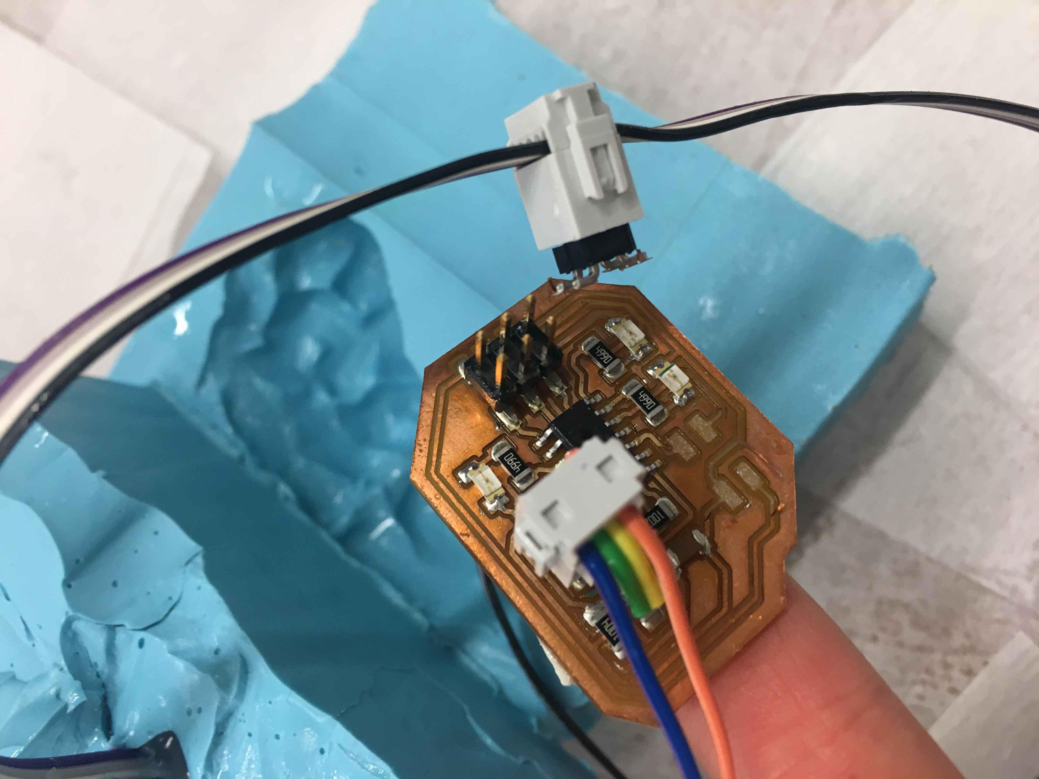
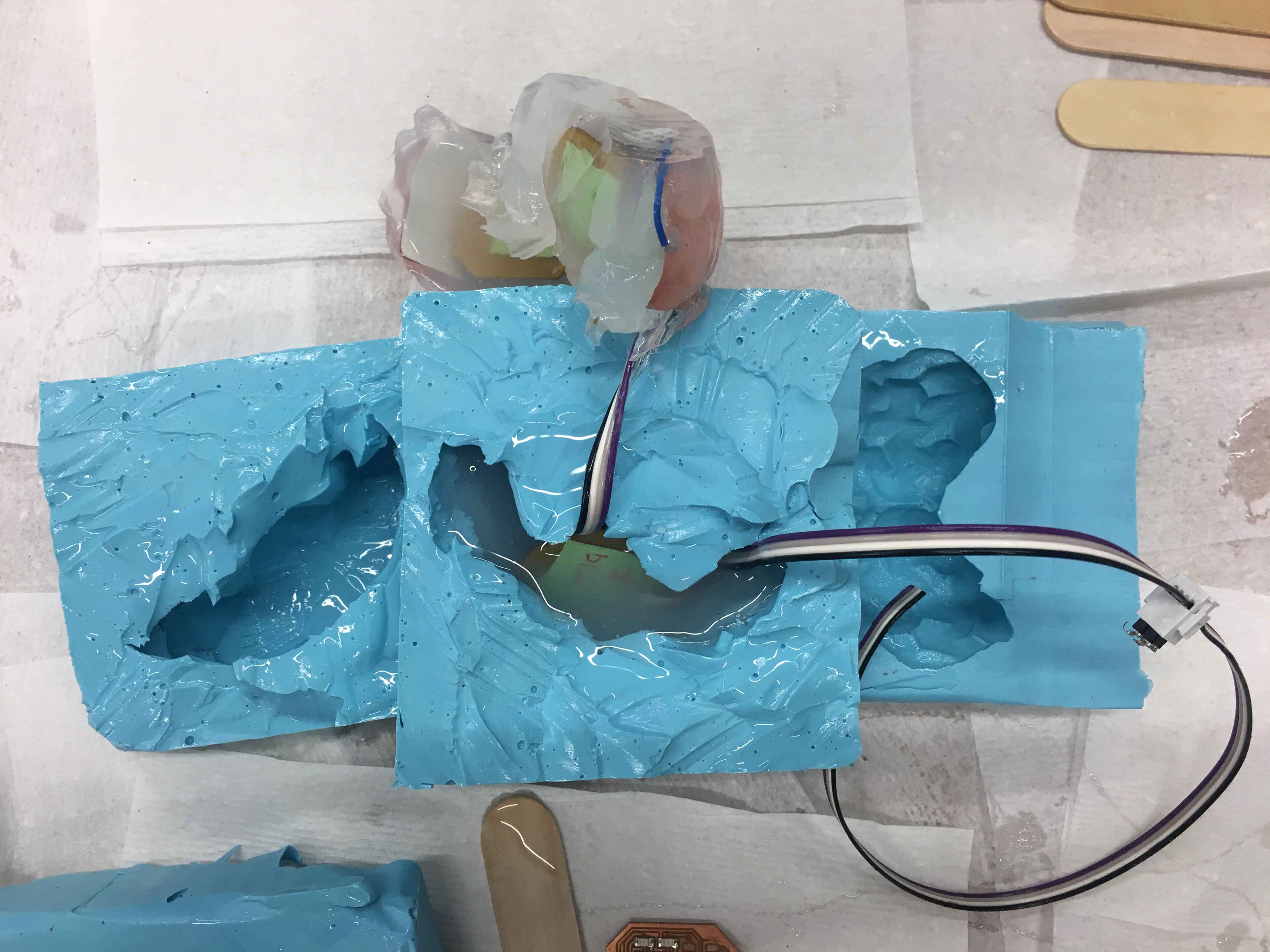
I wanted to cast two electrodes in Moldstar to find the best value for the difference in step response that will respond to someone touching the brain. I casted my board in some Moldstar. The step response was triggered to either a touch or by squeezing the material.
Then I tested each board separately with this setup. I also connected them all to make sure they can communicate with the serial bus.
One thing I noticed was that the led_long_delay() function I used (see my code below in programming section), blocked my code. So once one of the boards sent a data, it would turned the leds on, wait for 15 seconds, and turn them off. But during that delay none of the other baords could send data. So instead I added a blink_counter that is 0 by default. Once one of the boards sends a data, leds turn on and the counter increments by 1. Once it gets to a certain value, it turns leds off and switches back to 0. This way, the serial bus is available for other boards to communicate and the blinking counter happens locally on each board. To find what value I needed for the blinky coutner, I just tested a couple of random numbers. The current value counts for 10 seconds.
Next thing was that the step response took about 5 seconds to settle, so when I touched a board, it kept sending its node_id for the next 5 seconds. To solve this issue, I added a step_response_delay. So now the board senses a difference in the step response, serial pins become output pins, send data, turn leds on and the blinky counter goes off, then wait for 5 seconds, and the serial pins become input pins again.
Programming
This is the old code that I had developed in the weekly assignments.
This is the refined final code.
User Interface
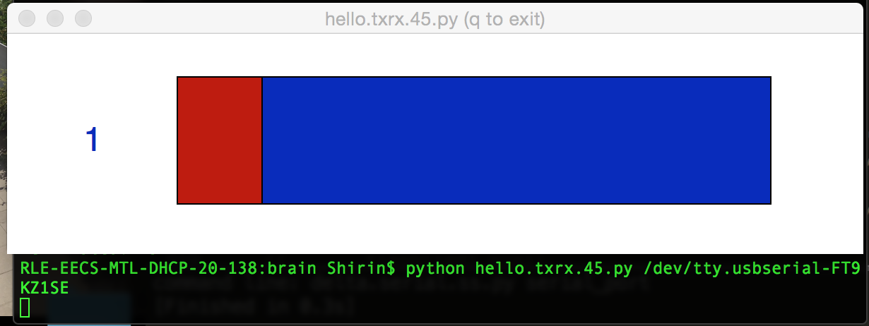
This is the code I developed throughtout the weekly assignments. It didn't successfully read serial data but the user interface worked fine.
Thisis the latest version of the code.
By looking at Neil's term.py code, I was able to read node_id of the board from the serial board and then map that to a page corresponding to the region of the brain that the board is in. The only problem with the current code is that the welcome page pops up, but the other pages aren't released until the serial communication ends. I though this was because of either time.sleep() or parent.after_idle() in the idle method. I tried removing them and moving them to other parts of the code, but couldn't get it working. Something to debug in the next developments.
Putting it all together
Putthign it all together was not so easy. When I was casting, I broked the bus header of one of the boards, becuase the board was too big, the opening of the mold was too small and I inserted too much pressure on the board. In the interest of time and (and sleep), I decided to not remake that board.
Casting all the pieces wasn't that easy either, especially becuase they didn't cured well. I also didn't leave enough wire length for one the piece, so I couldn't move the piece to its actual location.
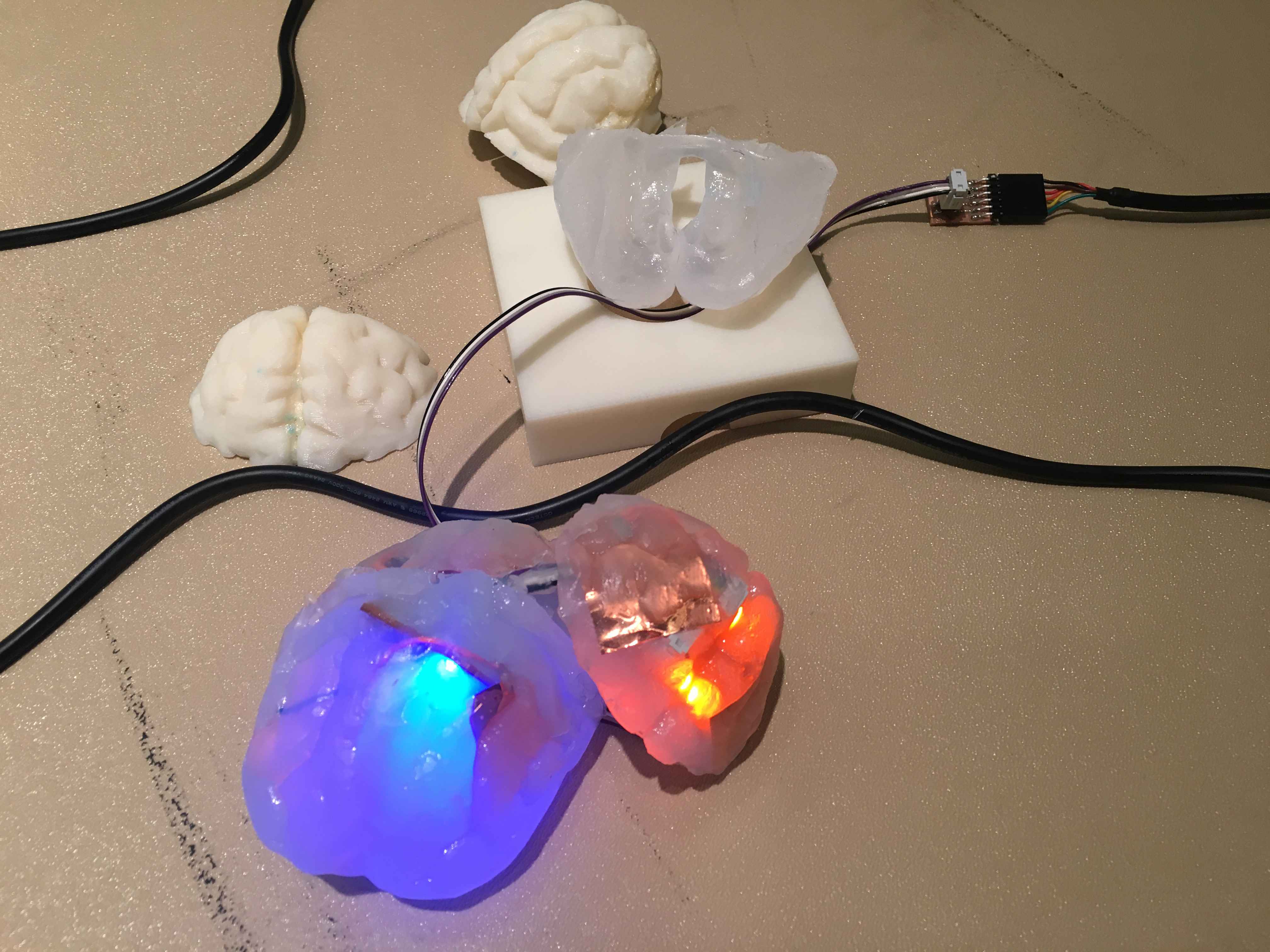
At the end, I tried to put the pieces together by adding some moldstar between the surfaces, but the wires and the fact that the material wasn't cured made it difficult. It also seemed to made the step response more error prone than before. I 3d printed a simple box with an opening for the wires to hold brain. After all, I'm happy with the brain I made!
Bill of materials
- 3D printing model material: ~8 inch^3
- 3D printng support material: ~2 inch^3
- Moldstar 20T: 1.5 lbs for $30
- OOMOO 25: 4 lbs for $50
- 5 successful printed circuit boards and 3 failed boards.