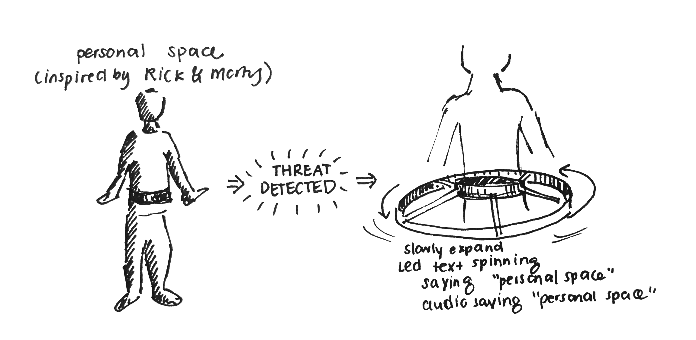
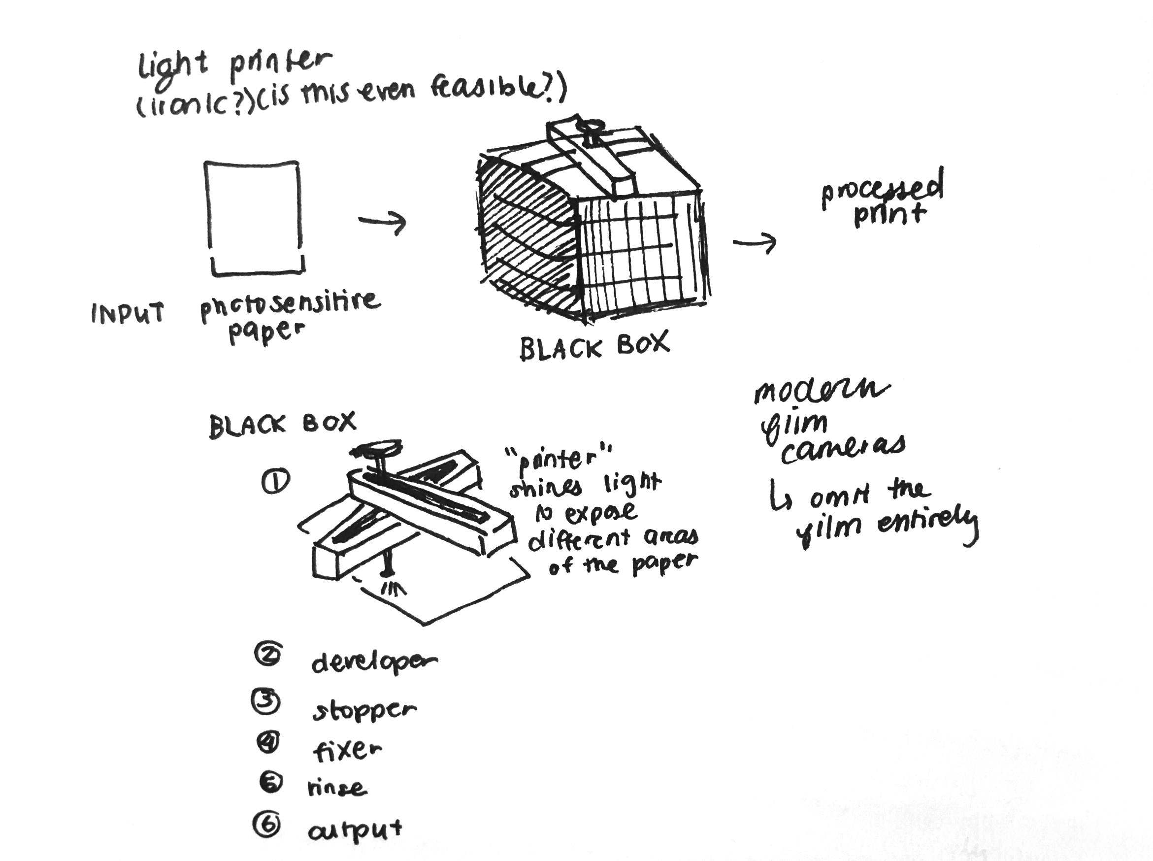
I originally planned on creating two wildly different ideas. The first was a device that a person wears that maintains their personal space and creates a bubble around them that preserves the personal space if it is vioalted in some way. My second idea was to create a light printer.
Here's a link to both of those ideas if you'd like to see more about them: Week 0 Assignment
Ideally, it would be a wearable device sort of like a belt. If someone is detected to pass a threshold, and is invading your personal space, the belt would activate, and expand like an umbrella, with an elastic band around it. An LED light array would rotate around the expanded form saying "personal space" while alarms or other audio plays until the invader has receded.
Last semester, I took 4.341 (Photography!). We heavily used film cameras in the class, which meant long nights at the dark room waiting for photos to develop, and testing numerous exposures on each photo I wanted to print one a time until I found the right one. What if you could print a perfectly exposed image in an automated way, without having to manually go through all the steps?
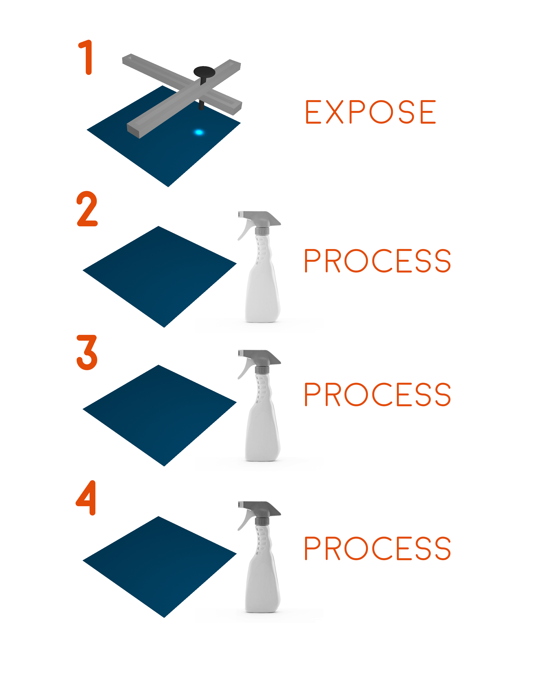
A light printer could, at some resolution, expose a photosensitive material with light based on its own calibration (no more guesswork!), and then iteratively spray photodeveloping chemicals based on the proper timings and saturation needed to develop images. Here's a quick sample of how I envision at least part of it:
I'm not entirely sure how the chemicals would be managed but I imagine a mechanical structure can apply pressure to spray bottles while those move accross the paper.
The next stage of my project was to determine feasibility over the course of the semester. In this process, I determined two specific things. The first was that my personal space device has several integral components that could possibly fail and ruin the ultimate functioning of the project if something were to go wrong. Because of its complexity, I decided this would be a future work that I could do when I can devote more time to it. I instead focused on the light printer. However, I realized that we'd be working on machine design later on and that the lessons I could learn from that experience would potentially overlap with this. Because we're already building a machine this semester (we built a toast-drawer), I decided out of the light printer and onto other more practical devices that I could use more often.
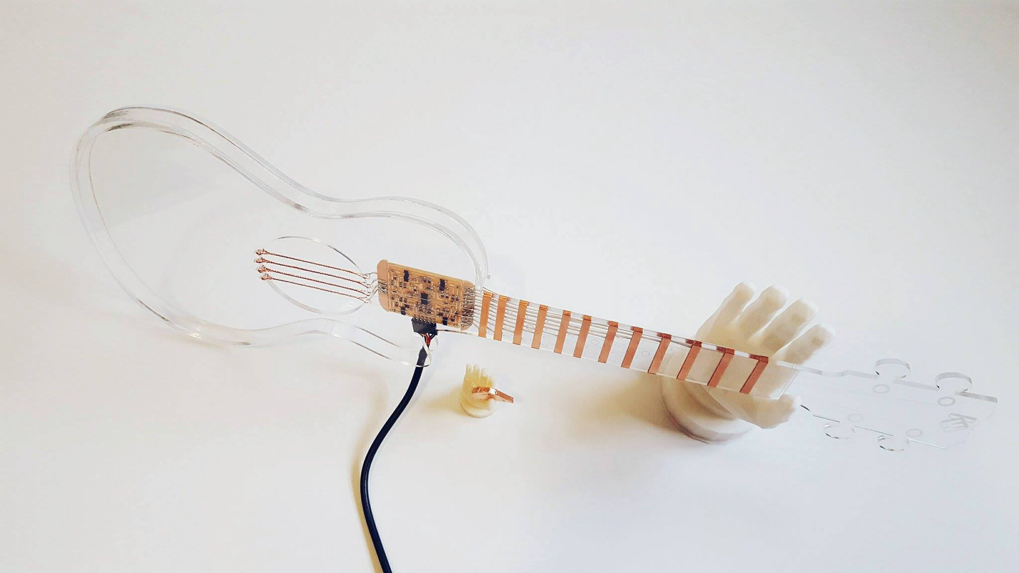
I then decided to build a capacitive ukelele for my final project. It would have a few major components:
Vinyl Cut parts for the frets
Laser cut acrylic base and parts
CAD-designed parts in general
Electronics design/Input Devices - capacitive boards that have many panels
Networking - wireless remote to modulate octaves or sound
Application Programming - build an interface for computer so that the instrument itself is programmable
With each of these lessons, I used my input devices week to build a prototype of a piano that would operate in a less complex way. I learned a lot in the process...
Here's a link to that if you'd like to see more about it: Week 8 Assignment
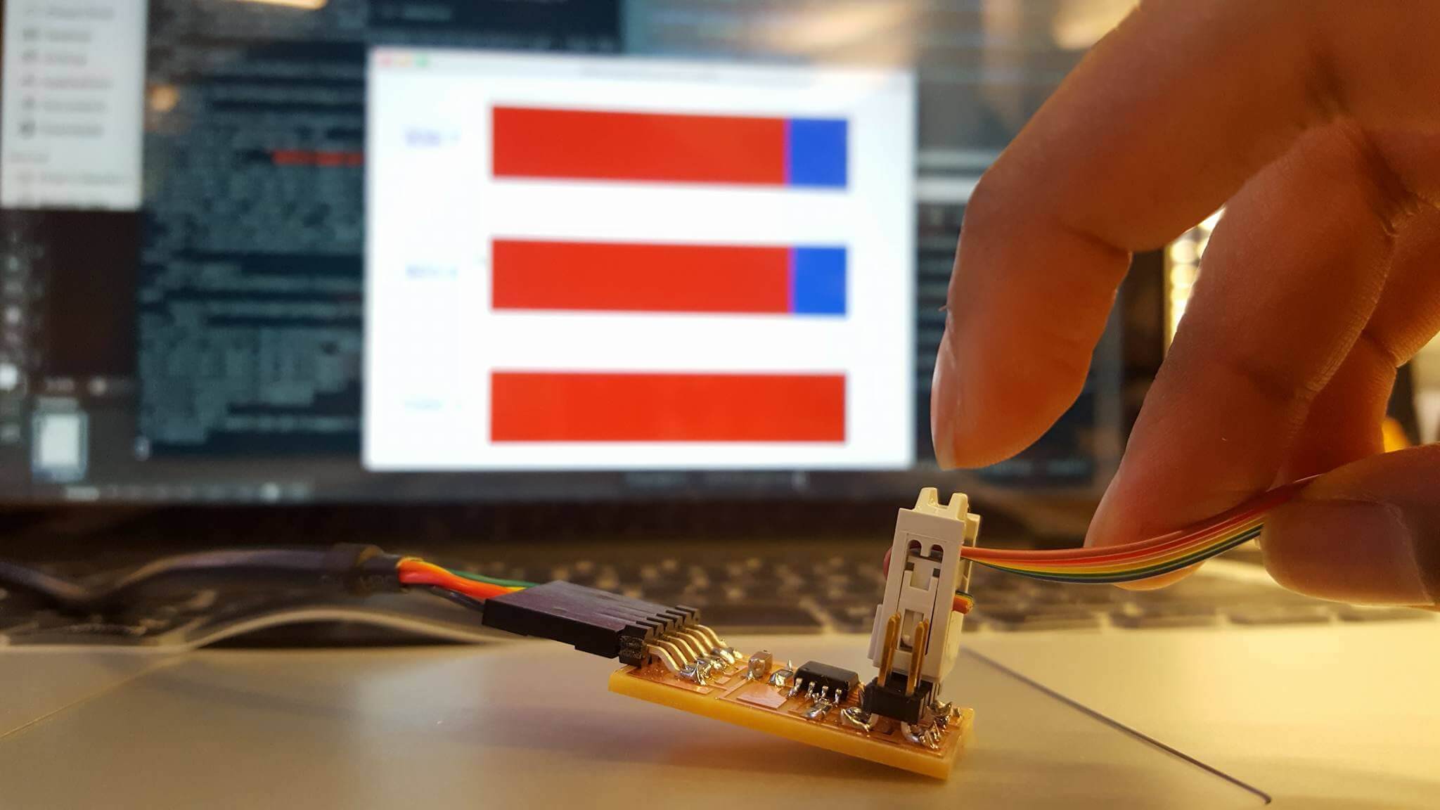
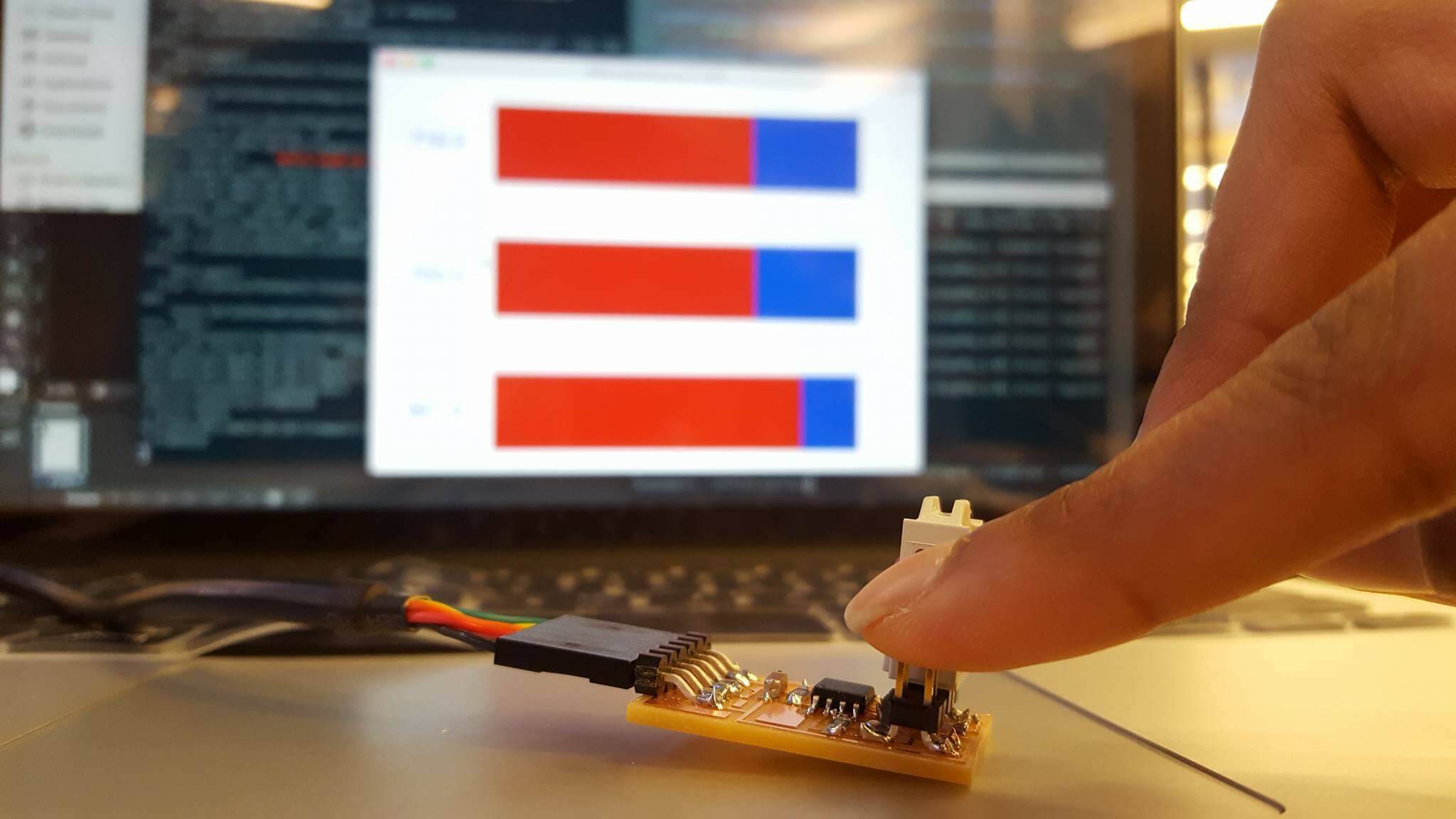
This week, we worked on input devices. I decided to use step response to make a capacitive sensing piano. It was a cool project to combine a lot of different skills we've learned over the past week. The first part of this week was milling a basic board where I could make sure I had things right and test out a demo to see how it worked. This part went really smoothly -
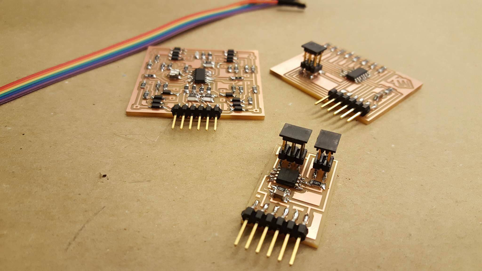
I milled the board on the site, and was easily able to flash it and test the board with the python visualization. Here are some pictures of that board!
And here's a video of it in action-
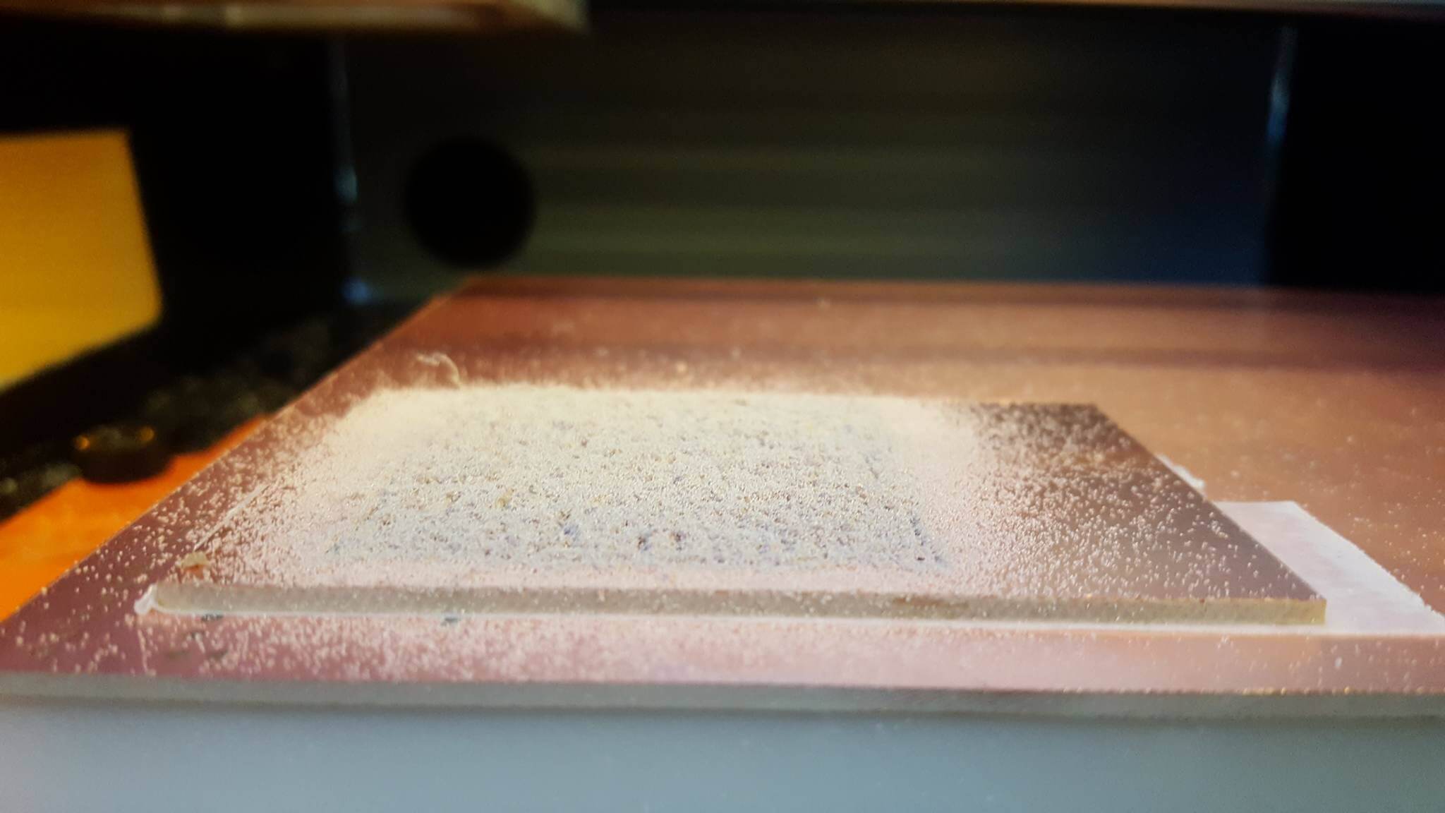
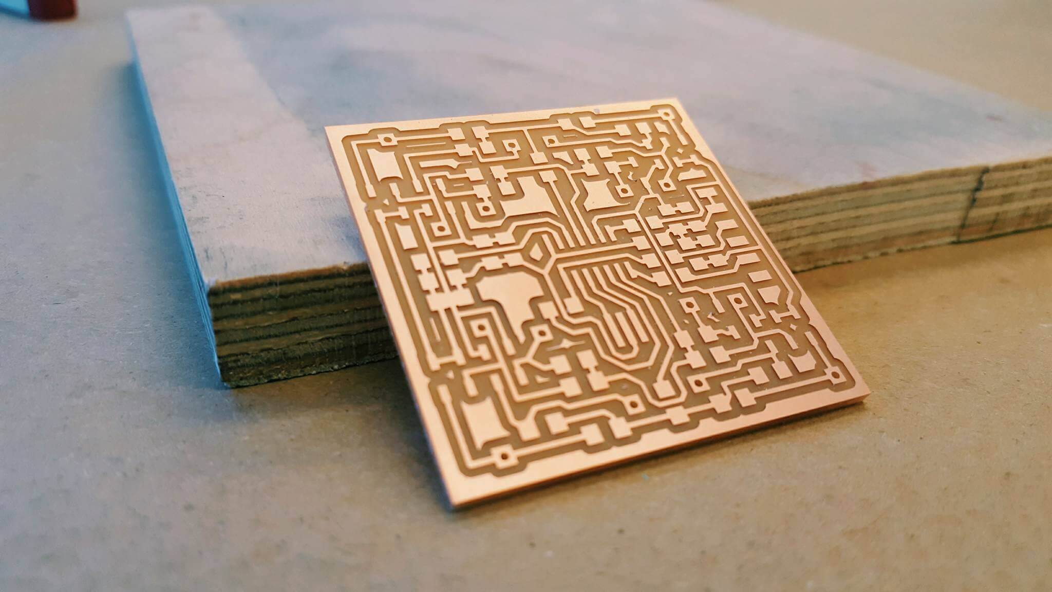
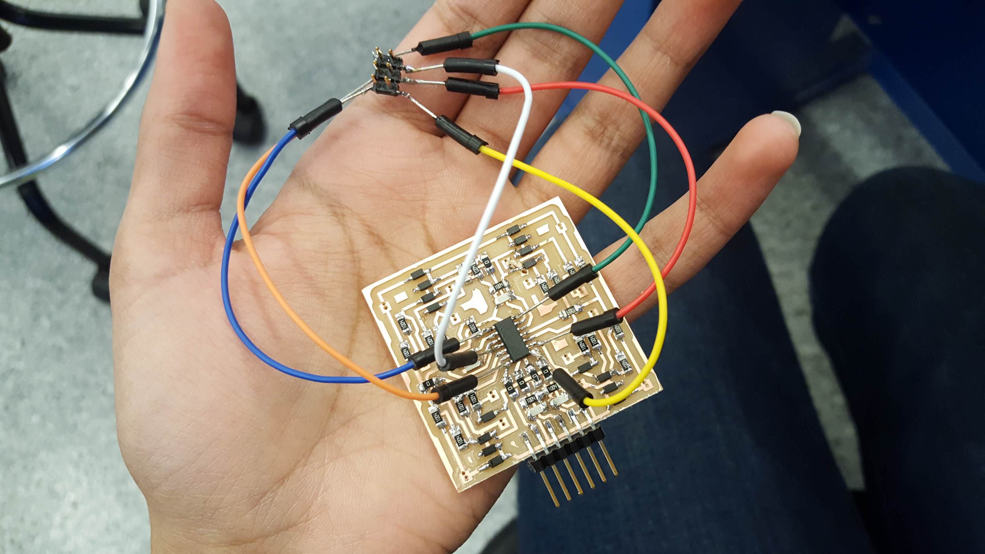
Next, I thought I'd take on Matt Keeter's multitouch board and adapt it for my project. I'm in awe that he found such a clean way to lay it out symmetrically- I tried laying it out from scratch and found that I needed to reference his board to find ways to make it route feasibly. Milling took a while this week since the board is bigger and denser with traces. I was scared going into this because I knew there was no 2x3 ISP header but I proceeded anyways- this page showed a method to resolve that, which I decided to go with(however janky it was).
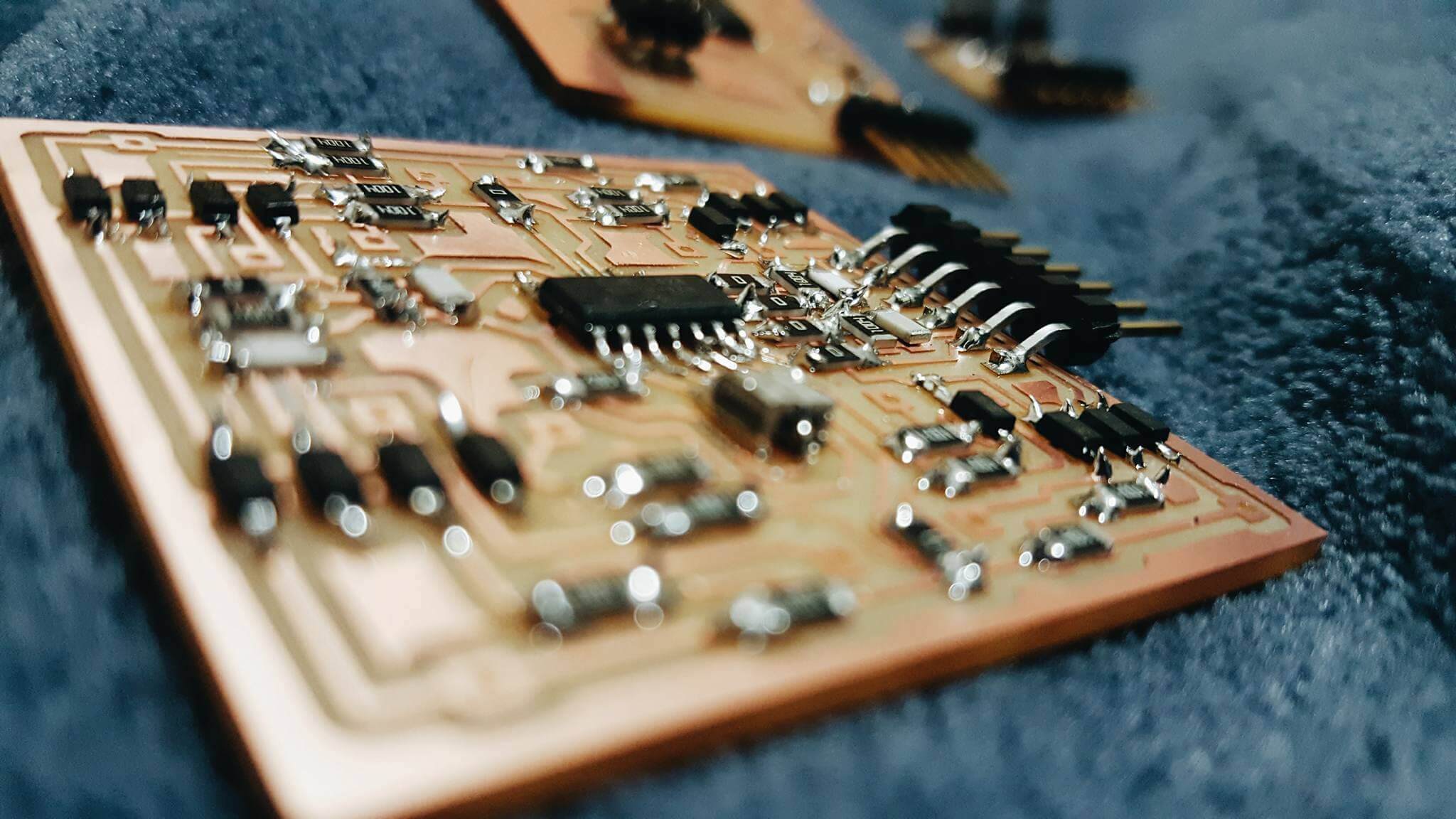
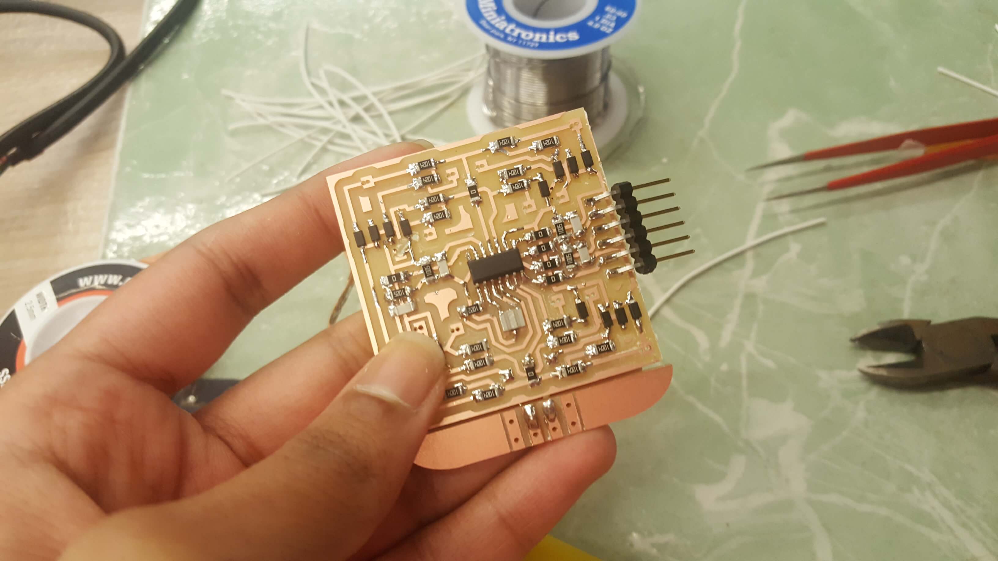
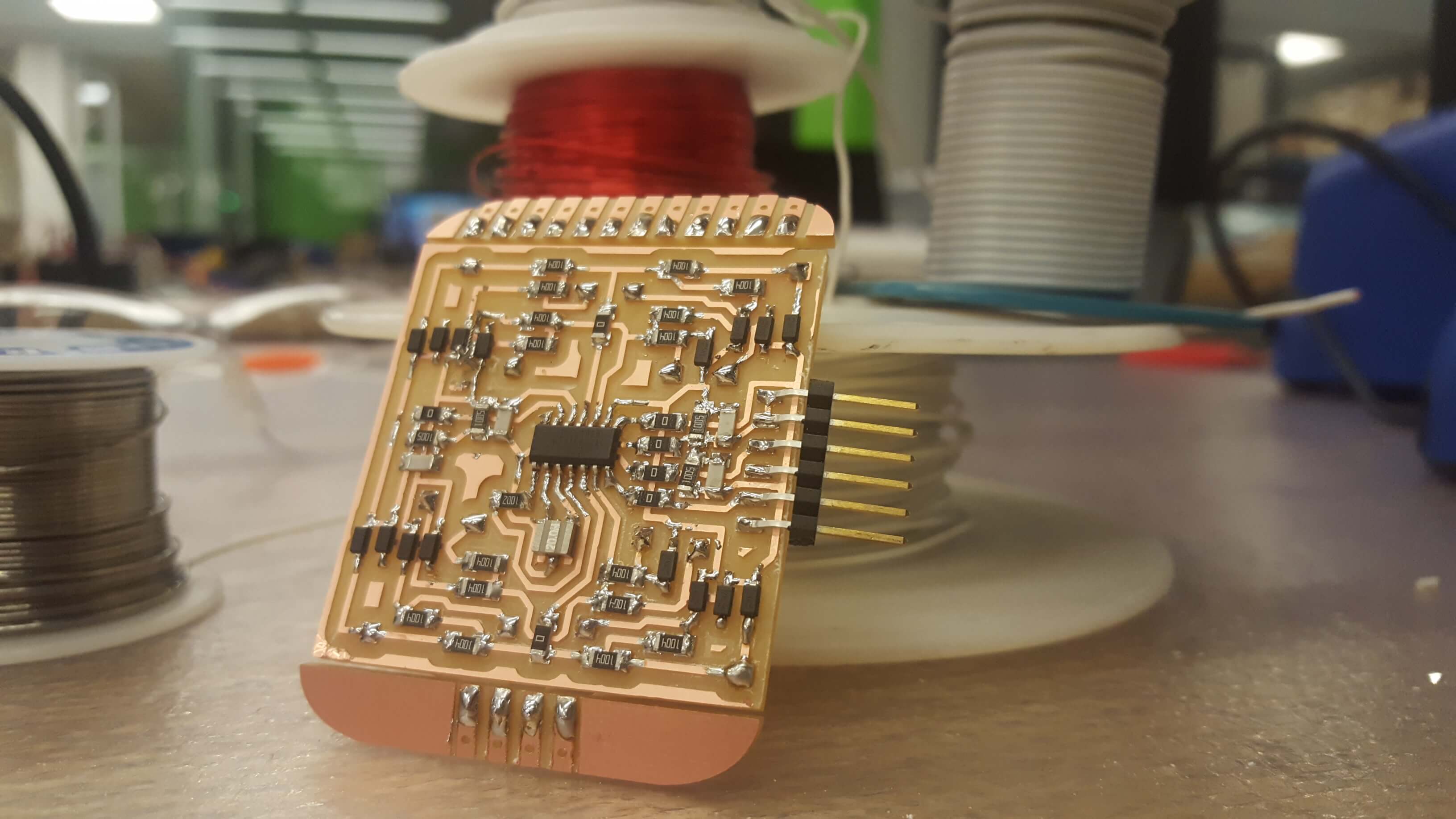
I found a sneaky trace that did not cut through so I adjusted that with a blade. Next was stuffing.
I attached the 2x3 header on next (this took a long time - highly recommend not doing this)
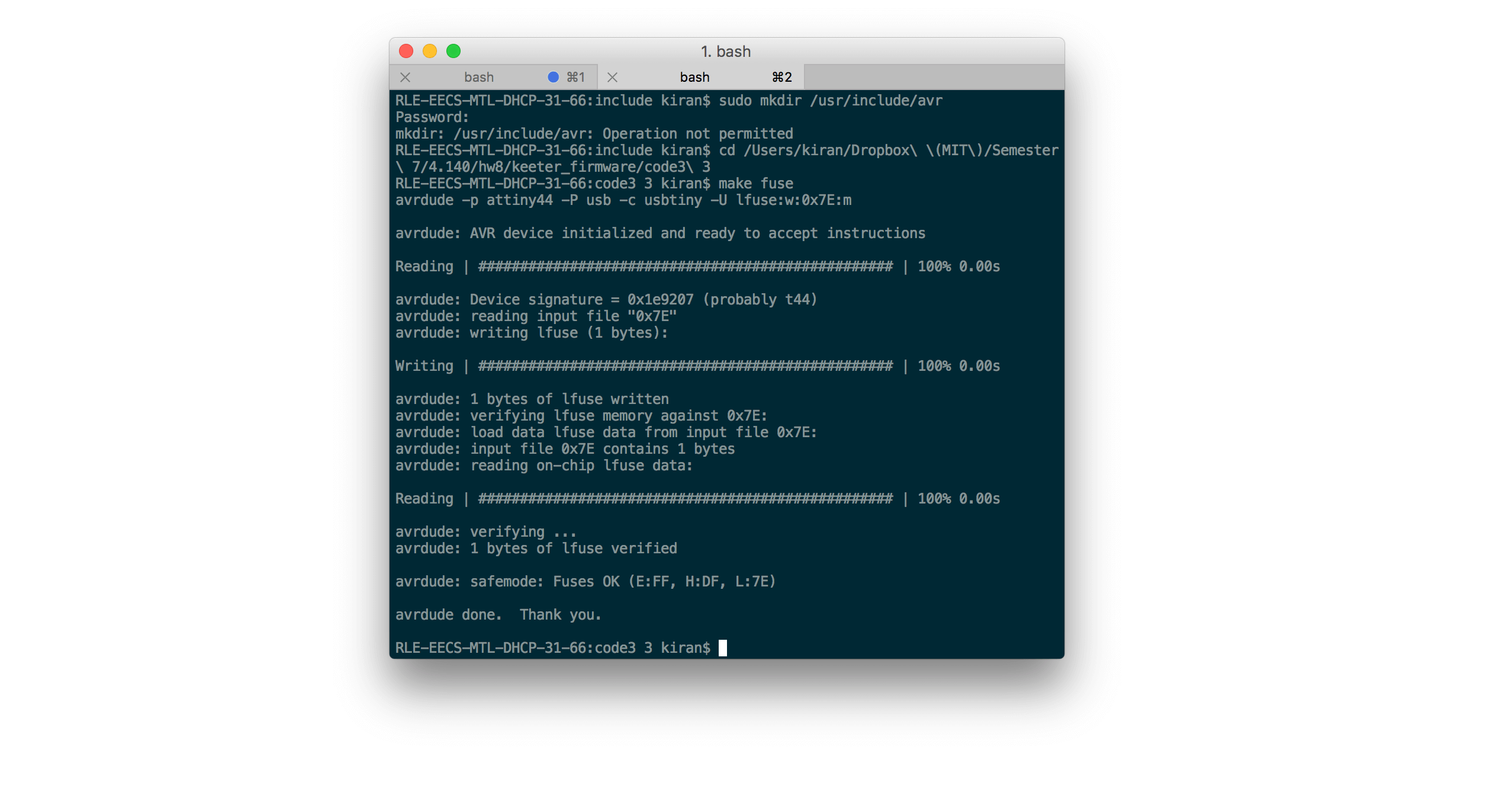
Finally, programming. I was able to make fuse but had issues with flashing the firmware onto the board. I found that changing the baud rate fixed the timing problems so writing ended up working.
Next, testing out the visualization. I found a consistent error that the port was busy and so I could not collect data from it. I tried consulting a lot of different resources online but to no avail. Once this part works, the Processing script I wrote should function easily- I have recognition on keypresses signaling a frequency to be played from my laptop (or alternatively, playing clips of pianos at certain notes so the sound is right).
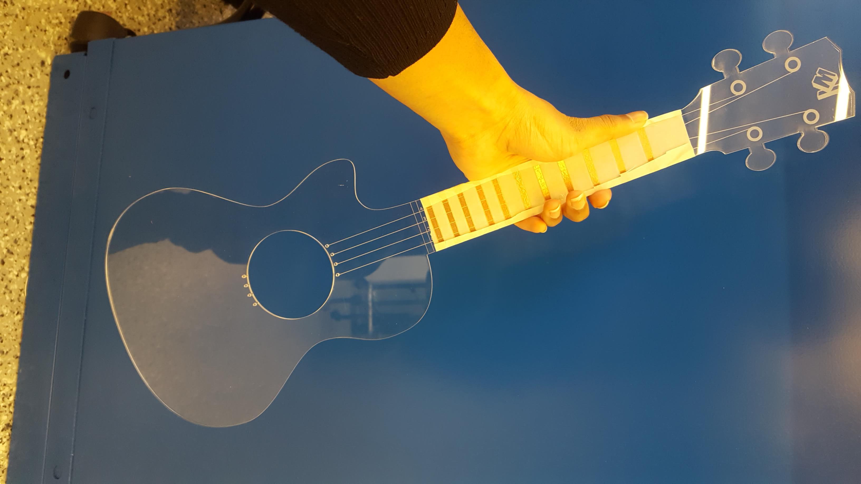
Here's the assembly in progress! (using laser cutting, laser engraving, vinyl cutting, and thermoforming)
I now have all the parts designed for my designs - I plan on laser cutting the base, a back and a middle part so that it can become 3-dimensional and thermoforming it to break its flatness and add texture and form. I plan on wrapping the copper around the edges of the neck of the uke so that I can solder wire directly onto the surface - from week 8 I learned that soldering through hole complicated the assembly and is best to avoid if possible since late stages of assembly get more and more difficult to do with precision.
The week ahead will require some milling, stuffing, embedded programming, application programming and networking!
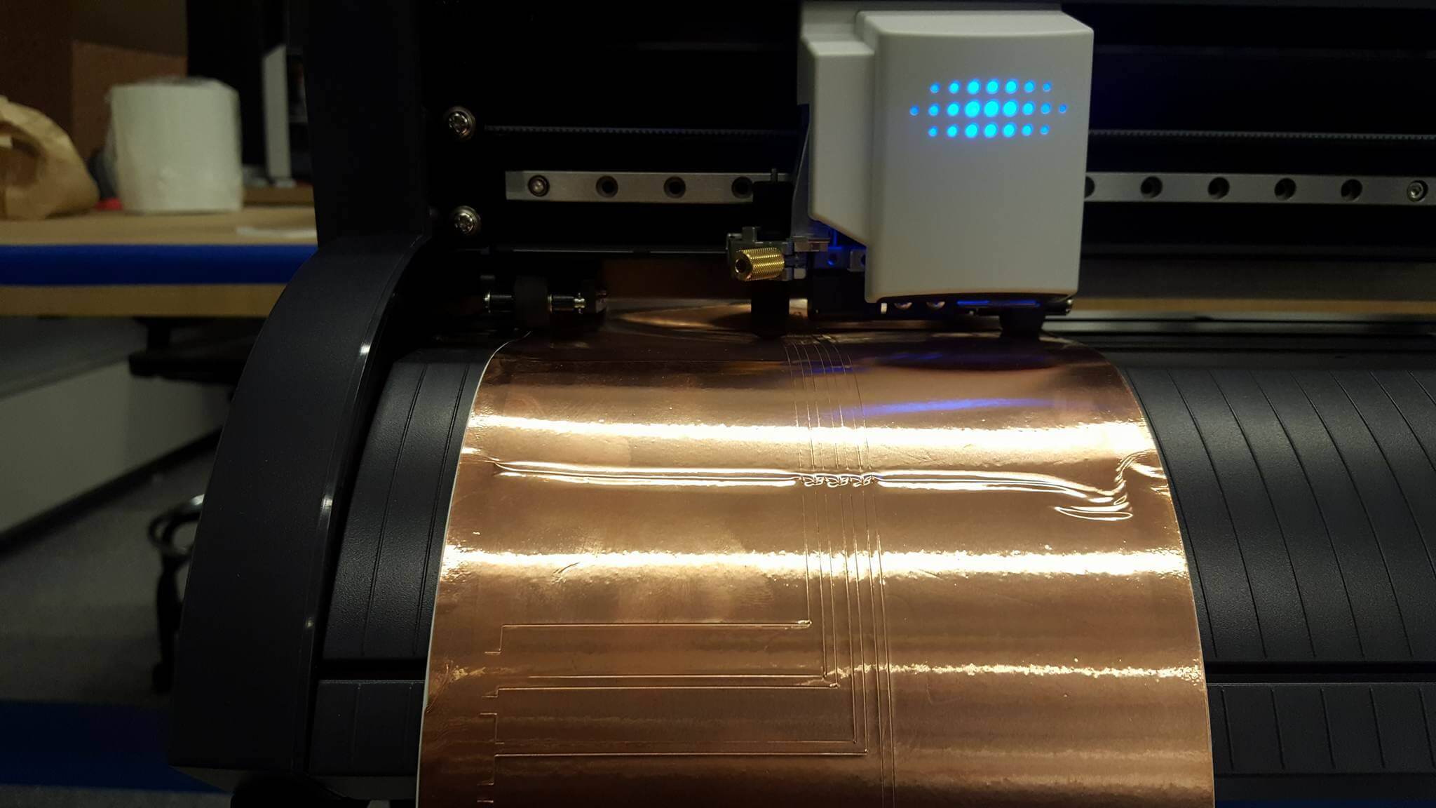
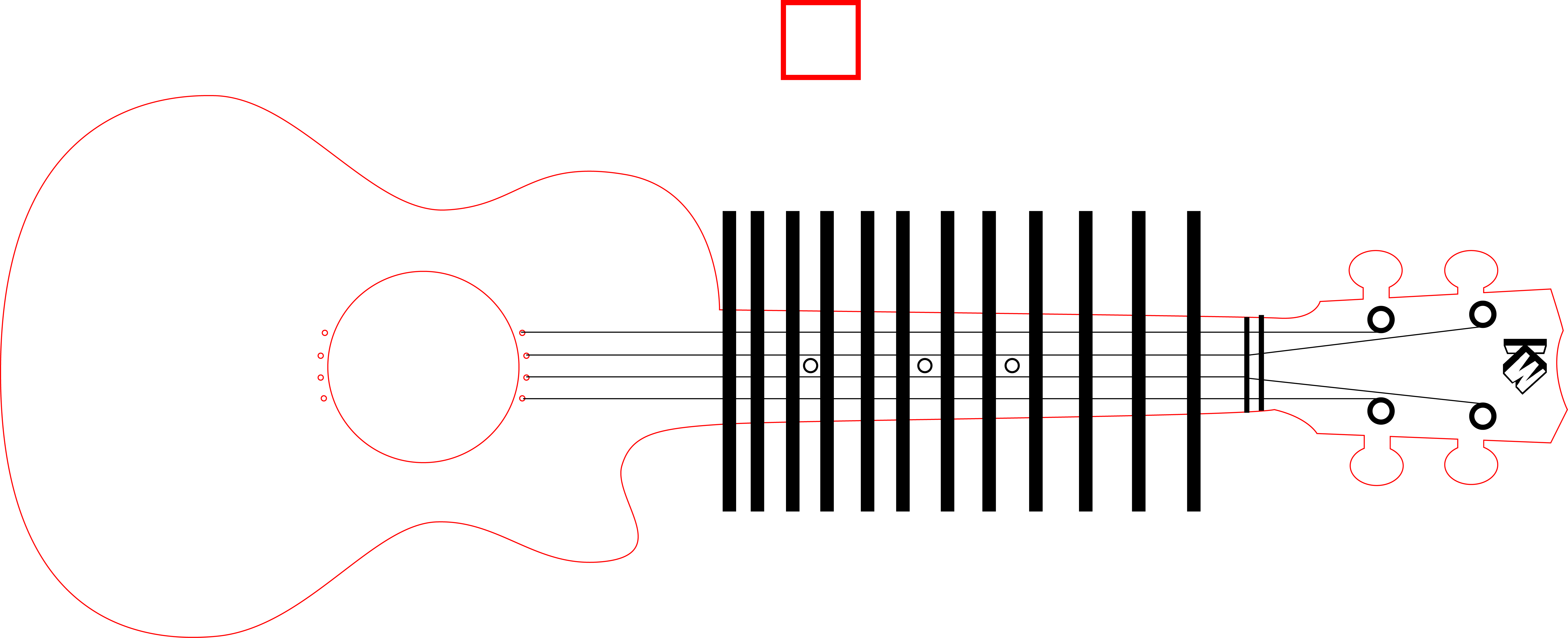
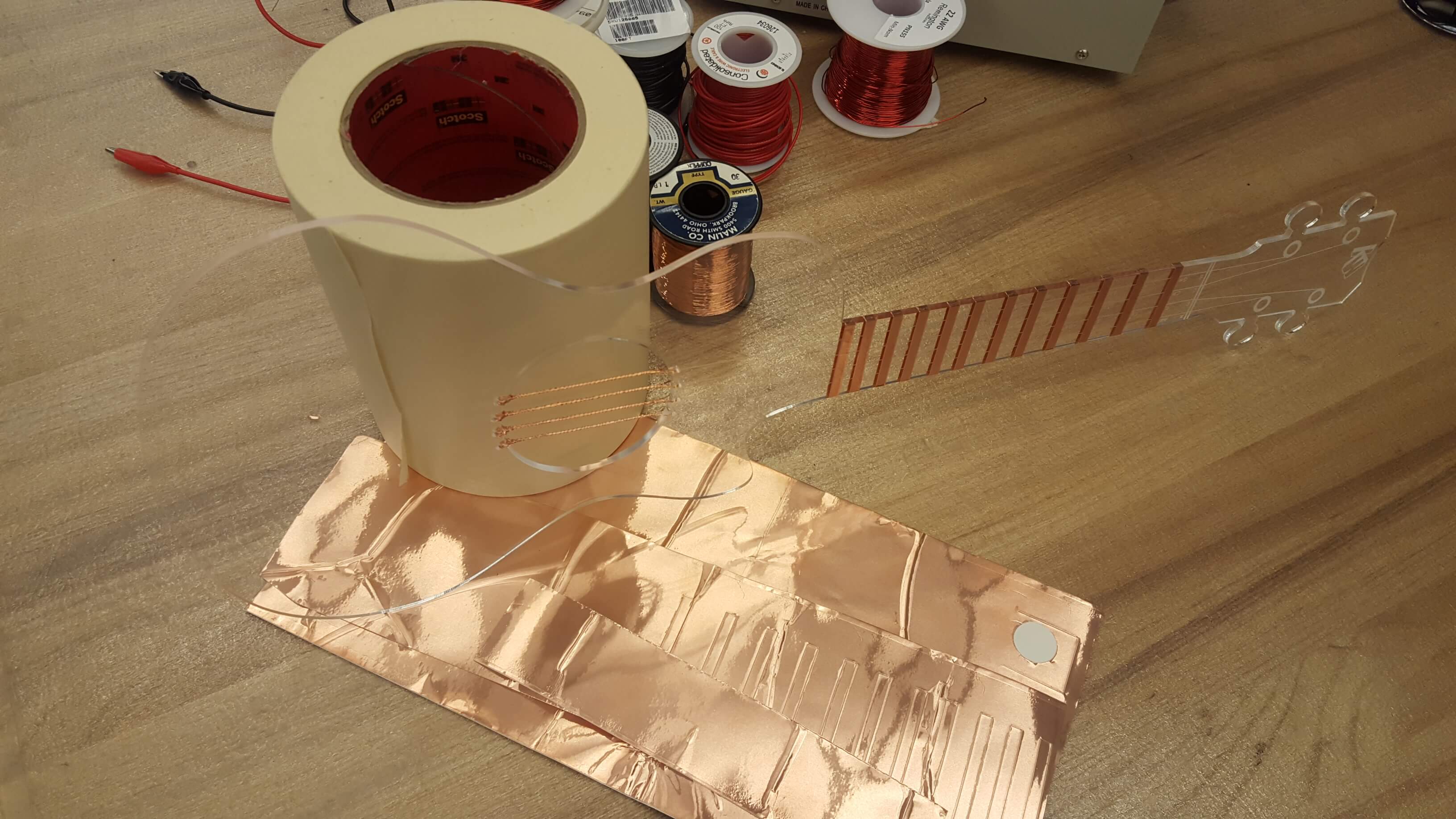
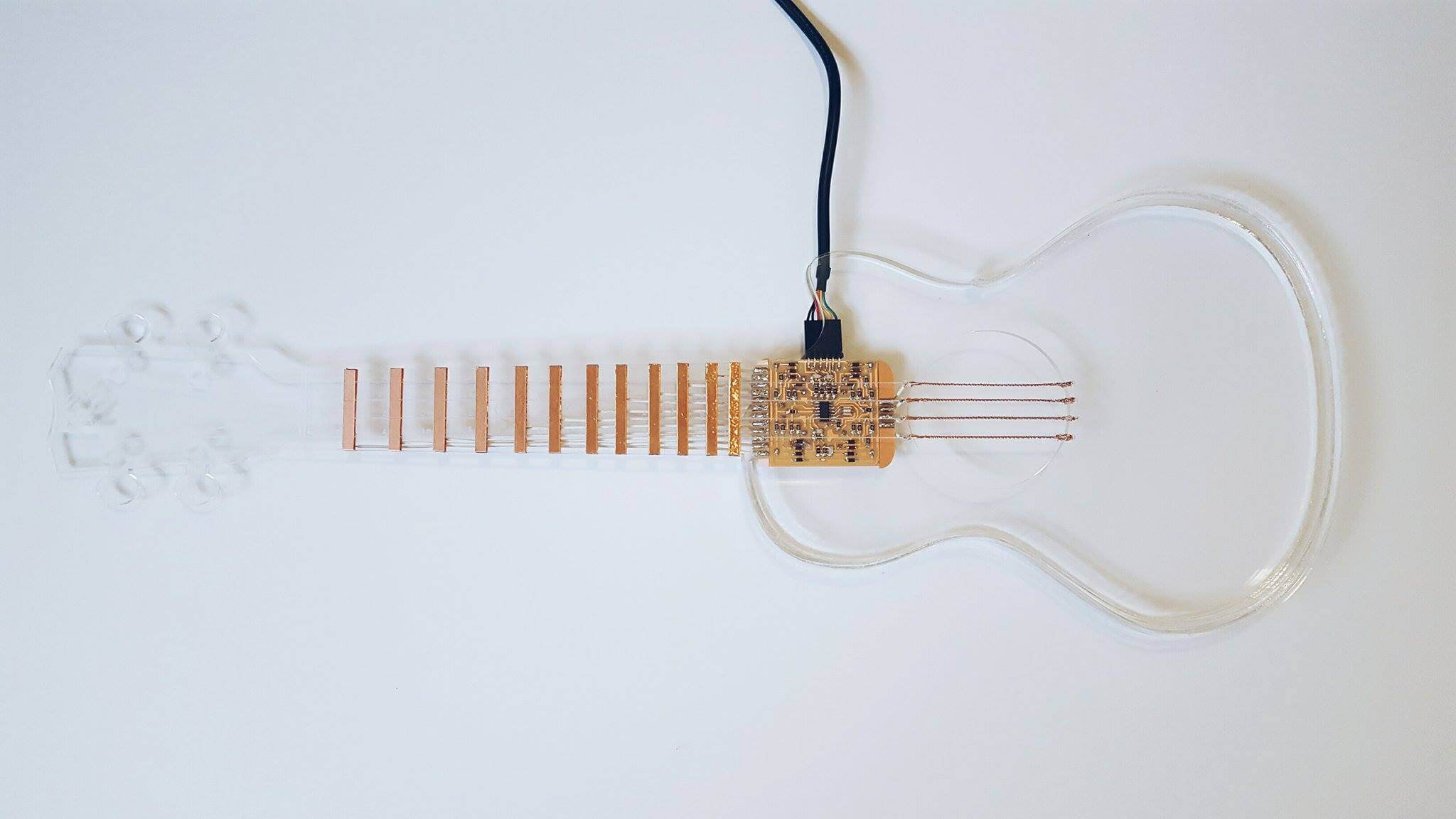
I laser cut a base for my ukelele which would be the main interface for user interaction. You can see the vinyl cut strips I also made for the frets here (theyre the black rectangles in my initial designs above)
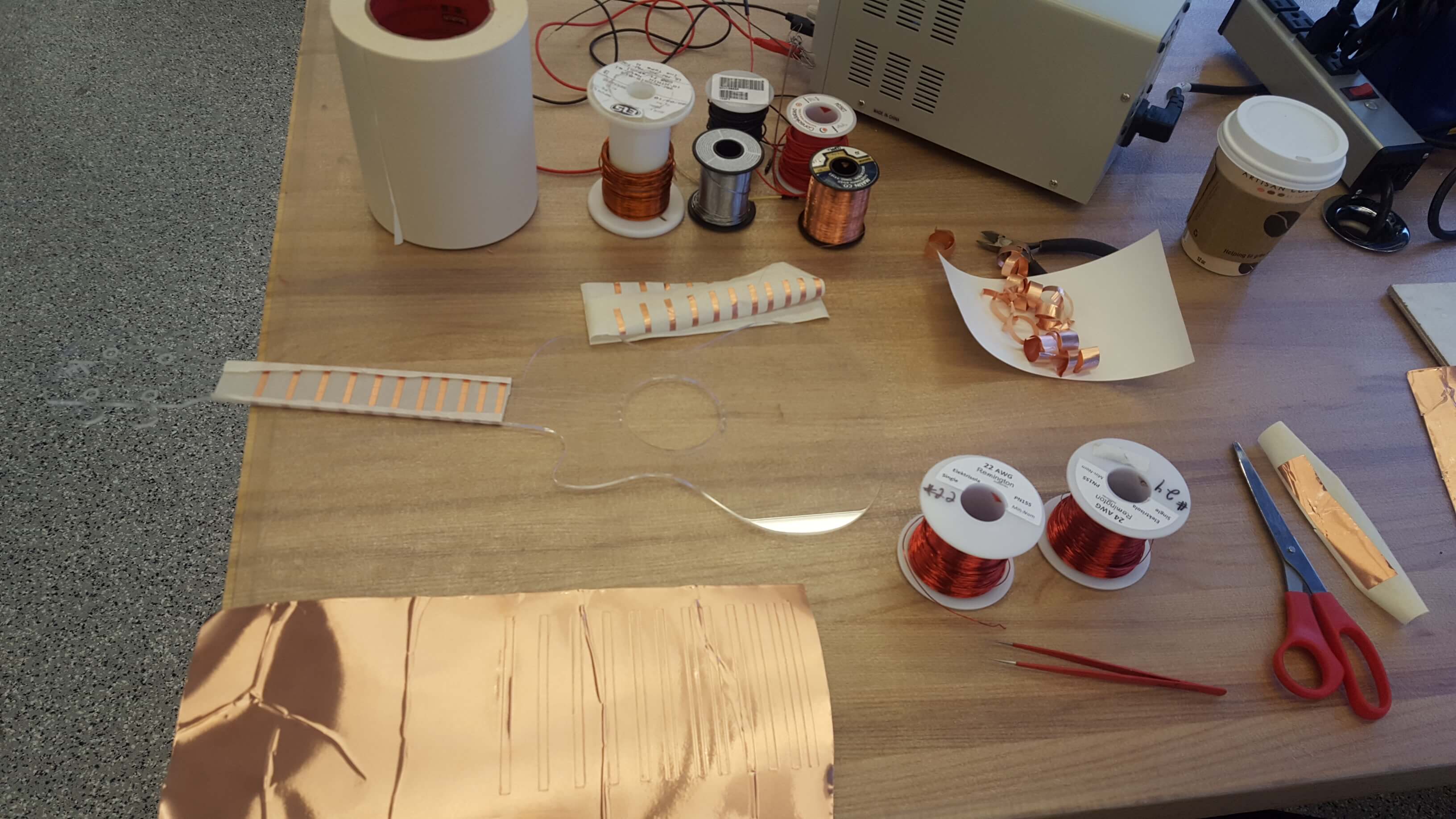
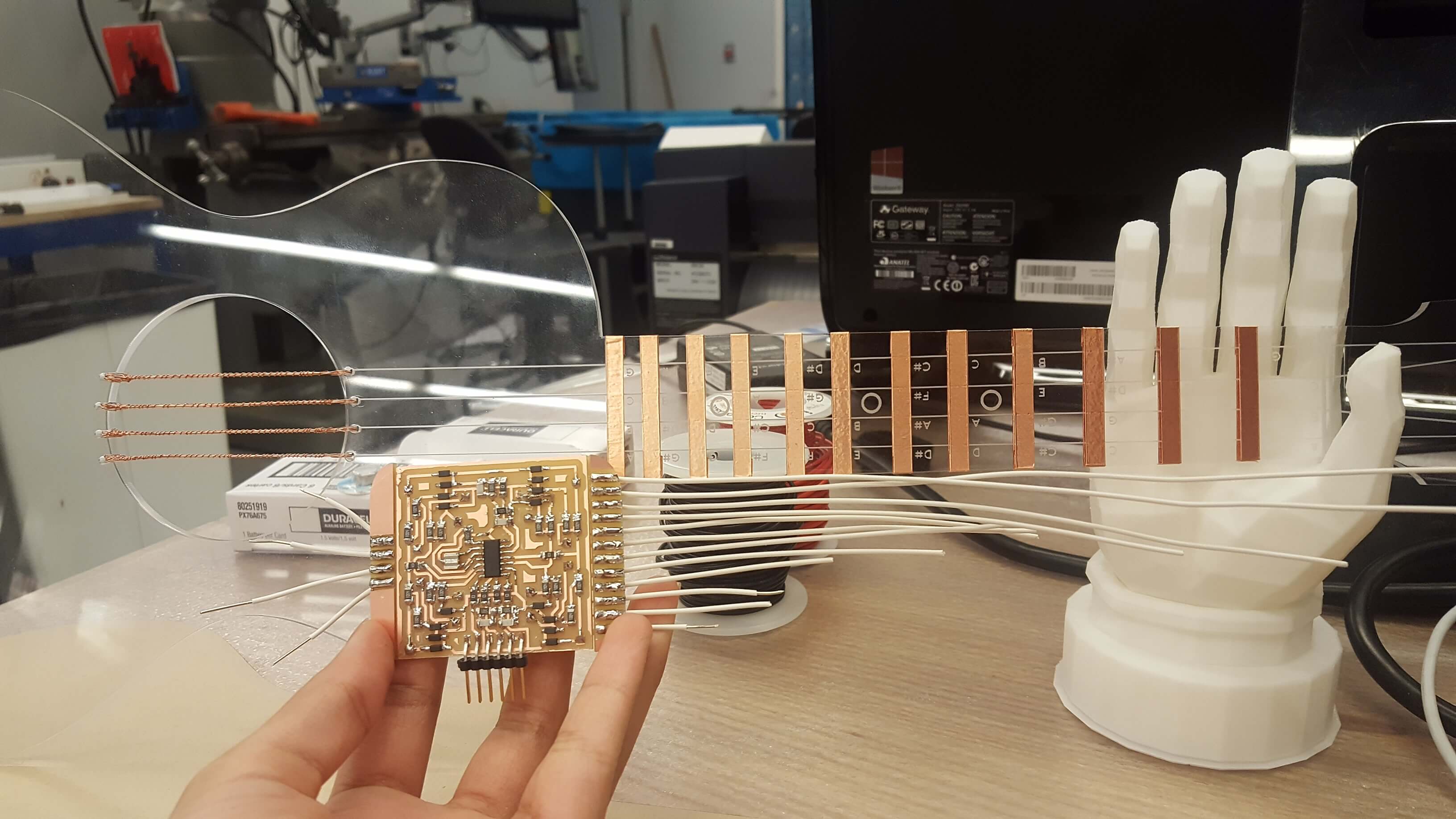
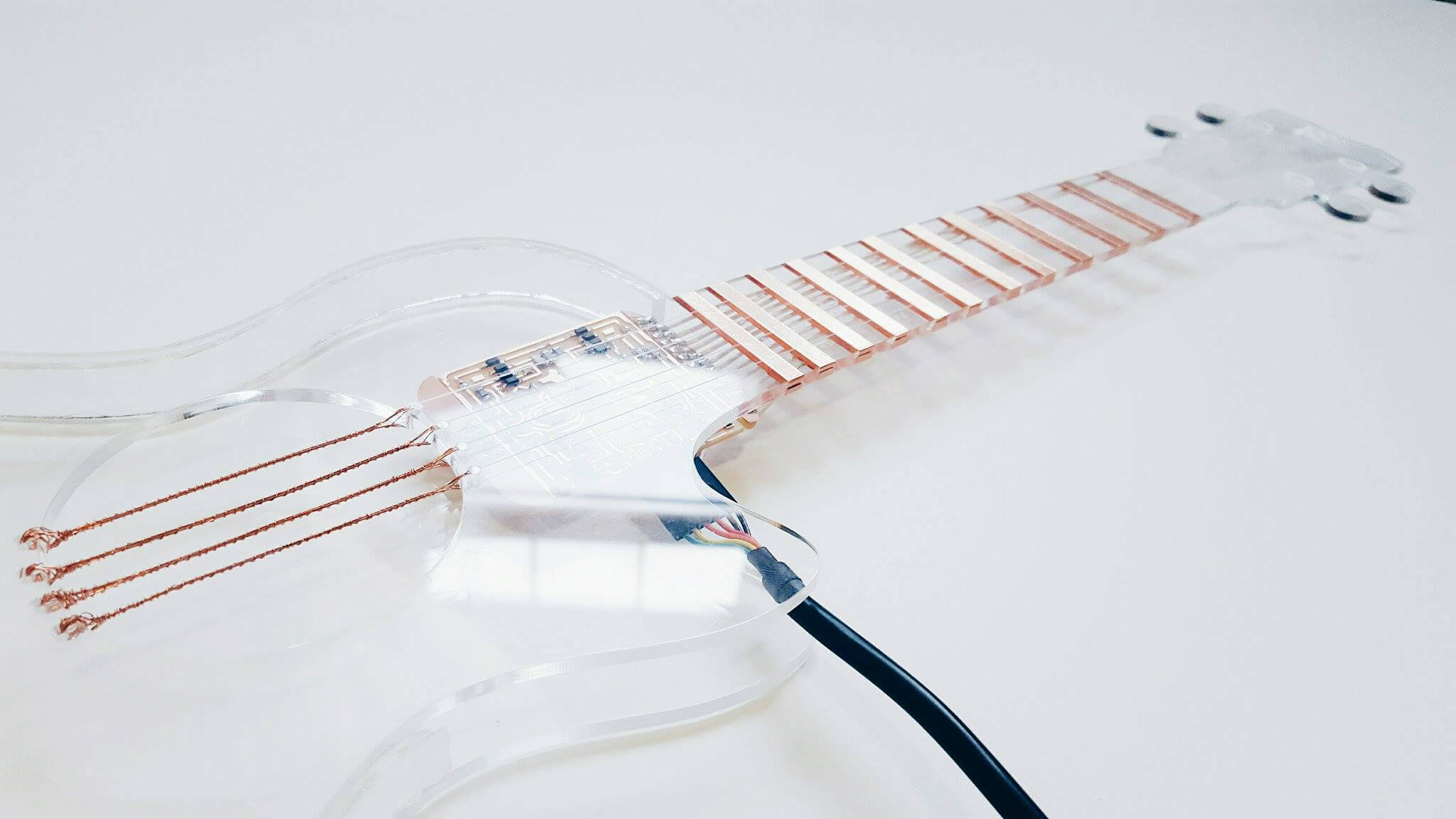
I applied 2 layers of vinyl cut copper to my ukelele's frets - one for the front and one for the back, so that I could solder all of my connections in the back to limit their visibility. I made sure there was some overlap between both strips too to ensure a solid connection and checked those with a multimeter.
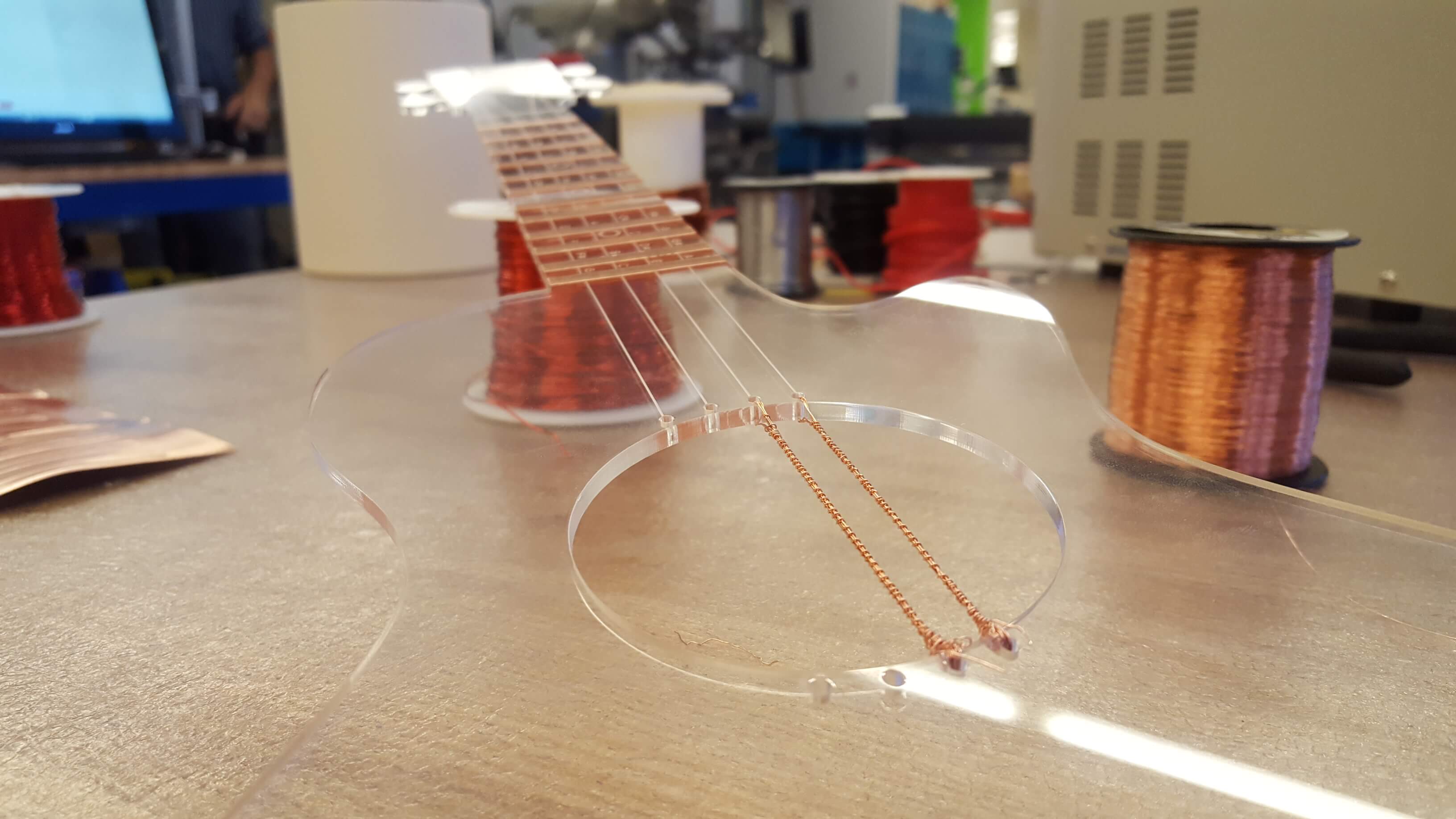
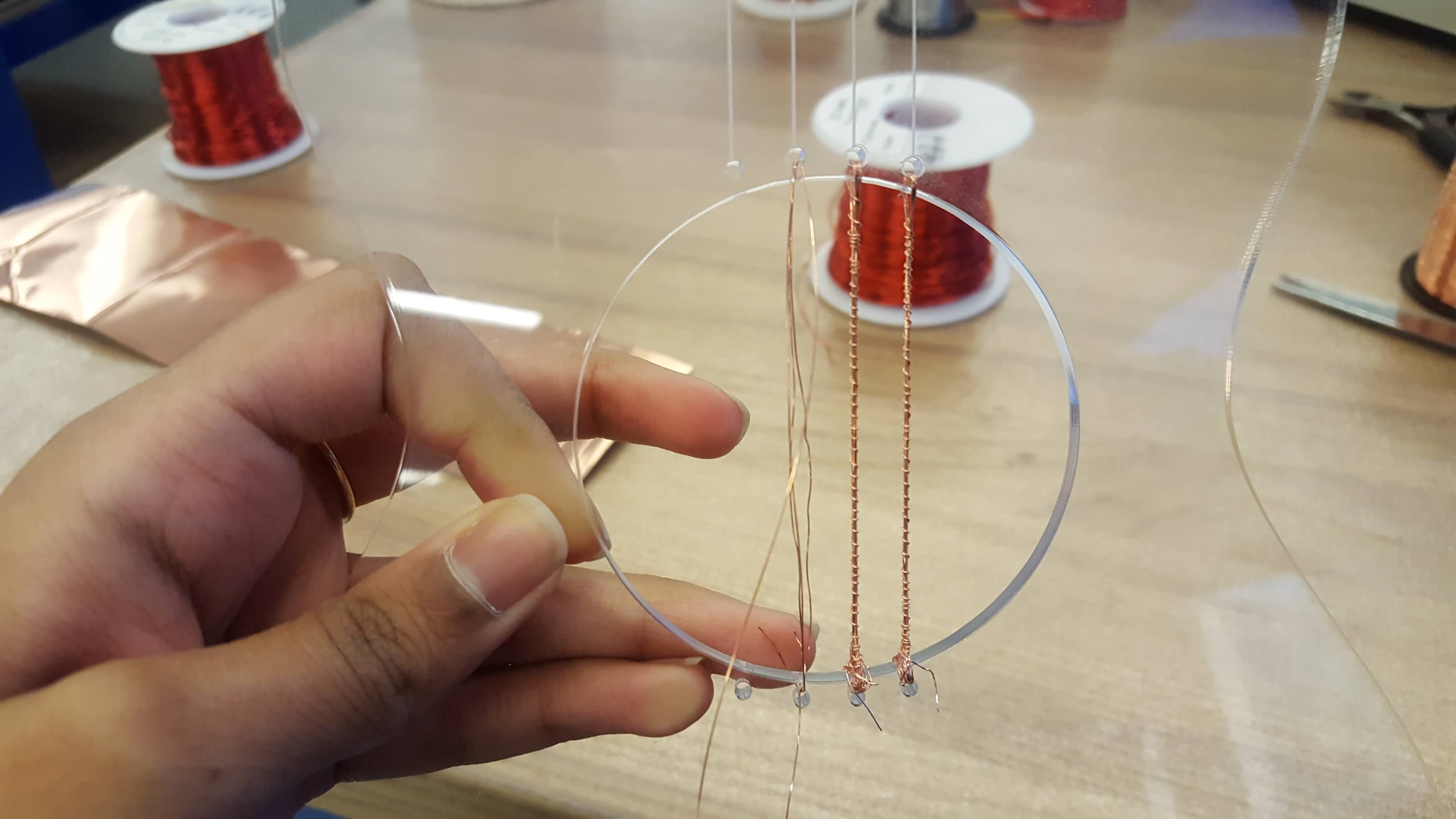
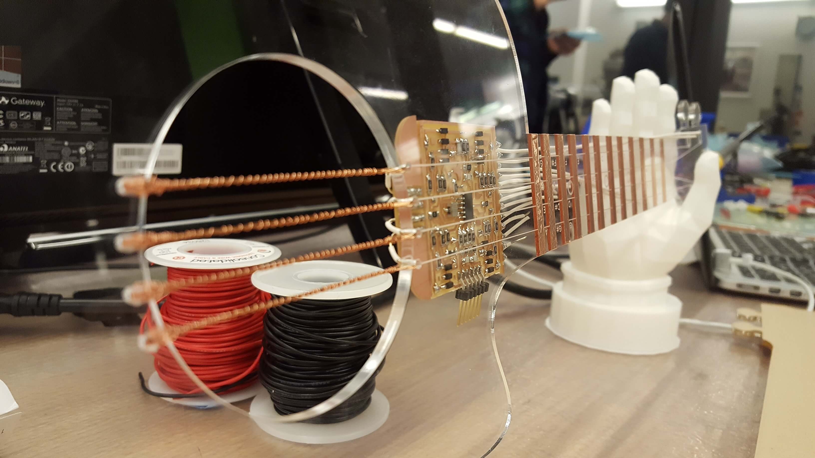
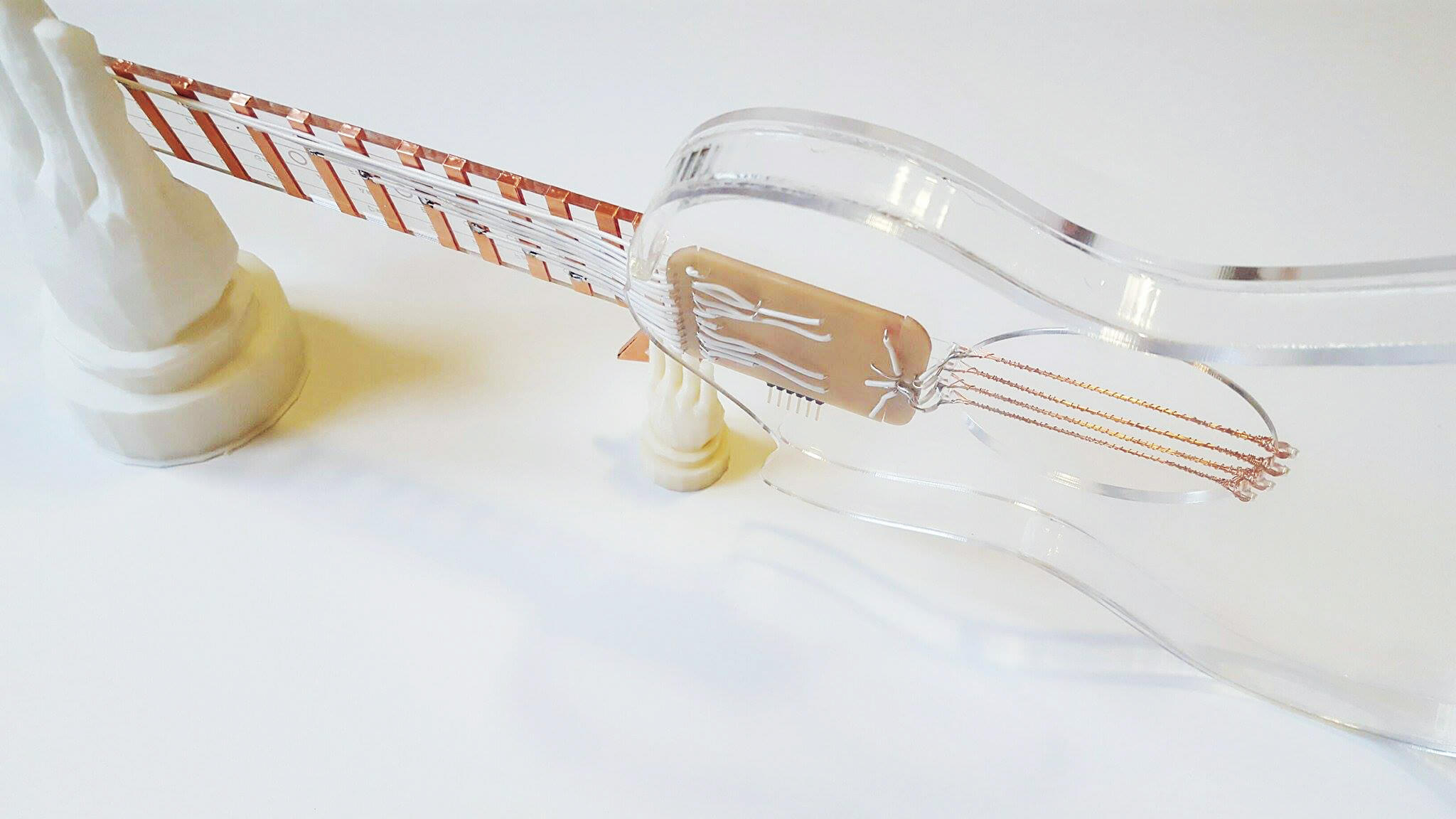
I couldn't find the right gage wire for my strings at the bottom of the uke so I decided to wrap several layers of a thinner gage and wrap the wire around it all - the motions of assembling this part felt like sewing and were very time intensive but gave me a much better looking and functioning result (the other wire that was the right thickness was bright red).
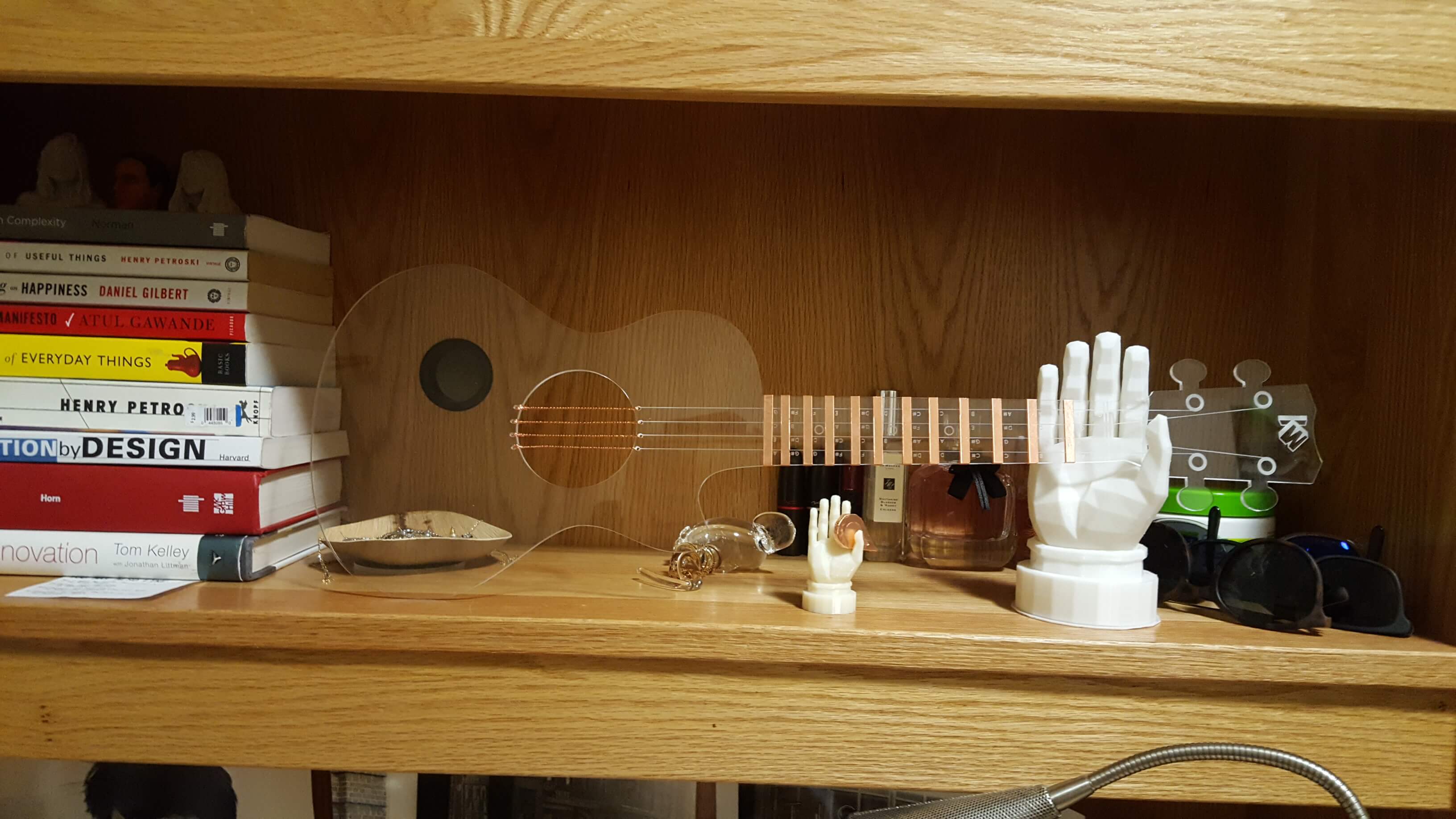
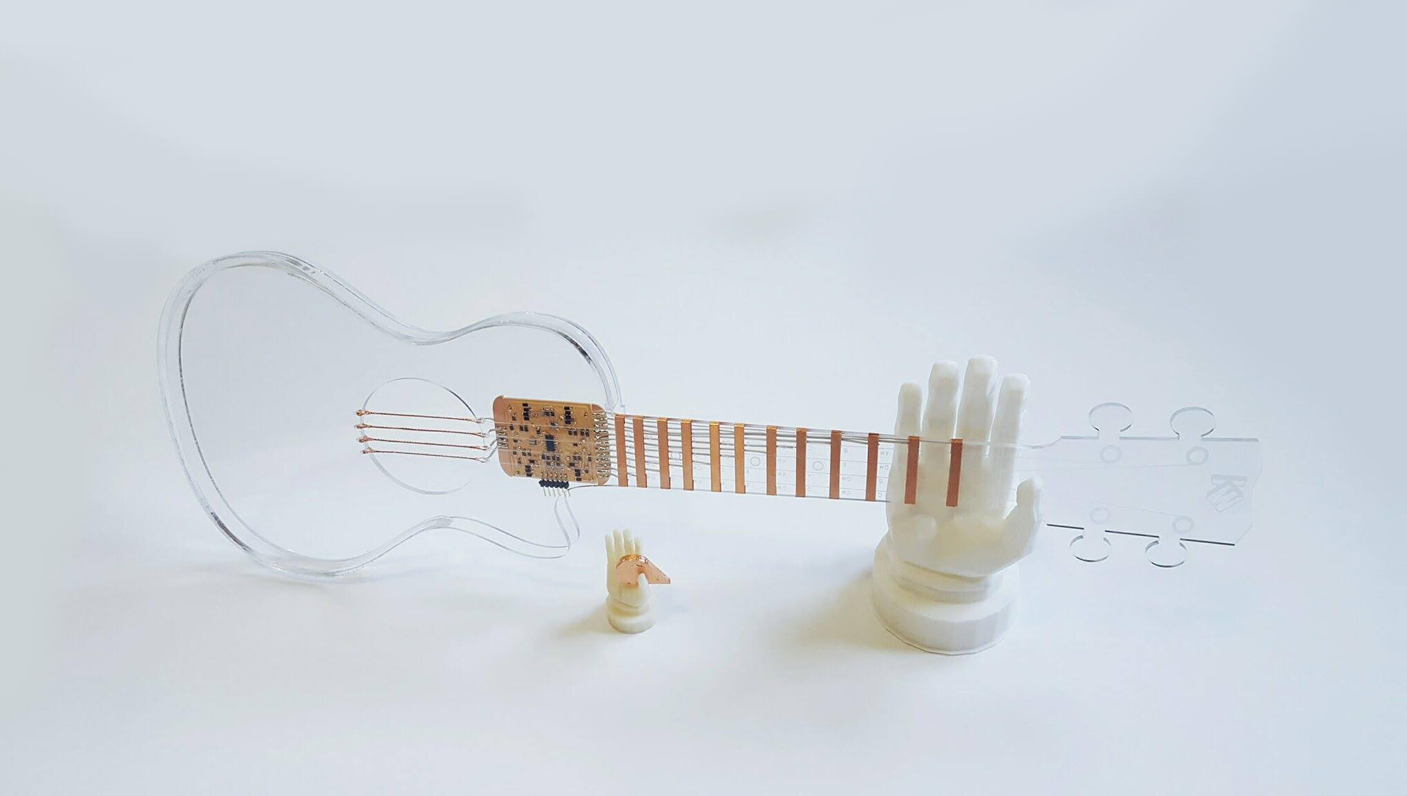
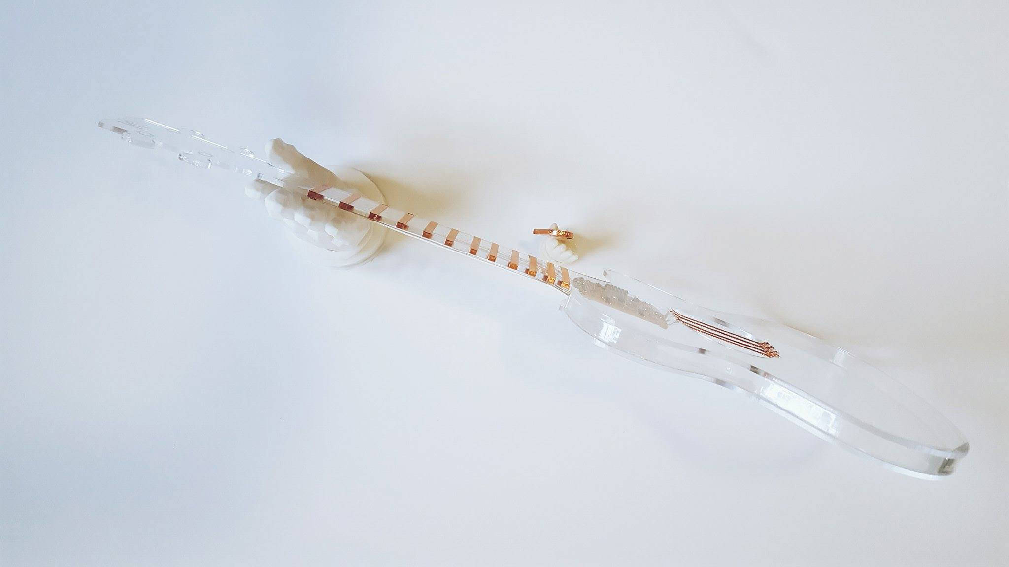
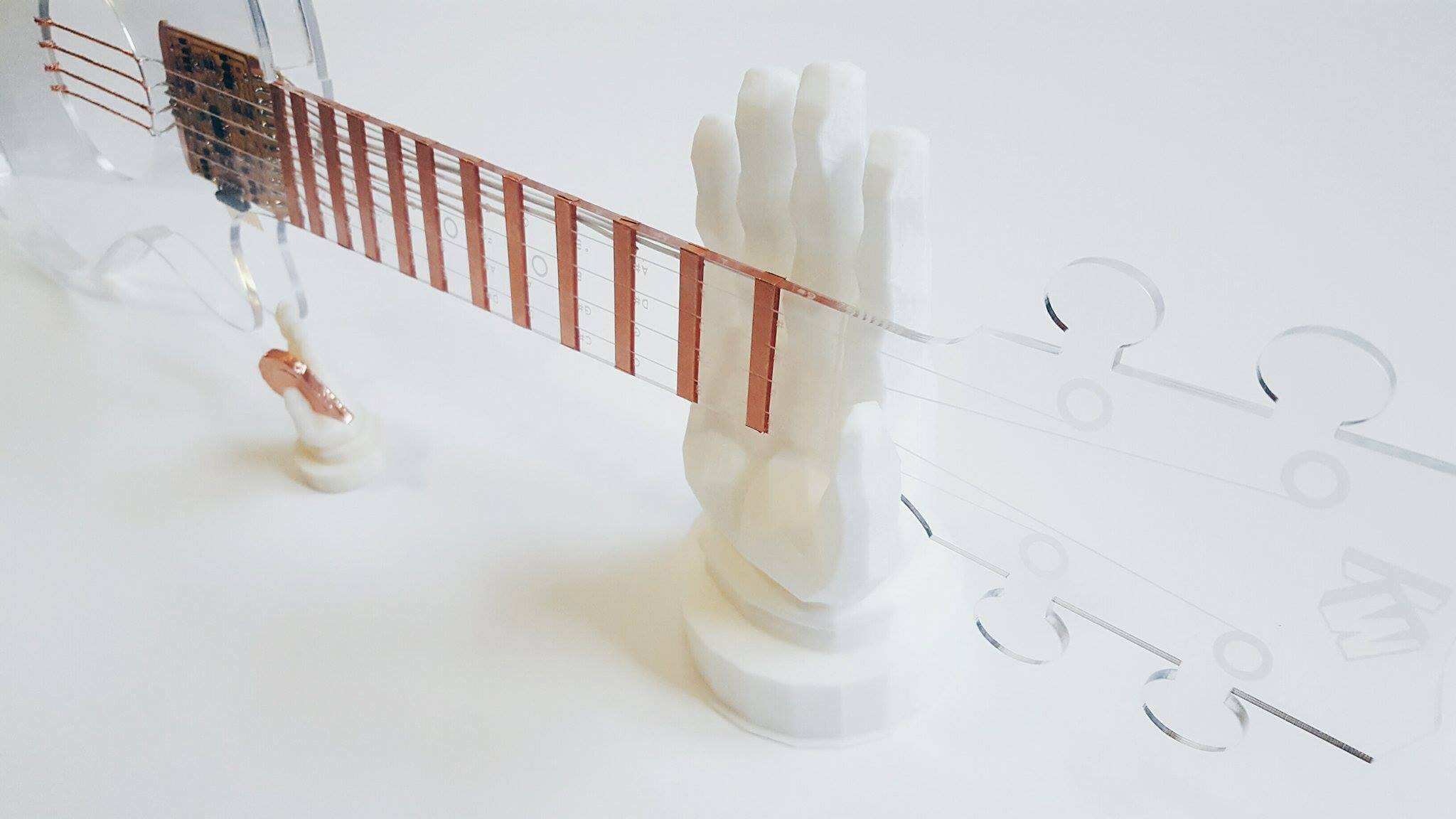
The fully assembled base of the ukelele!
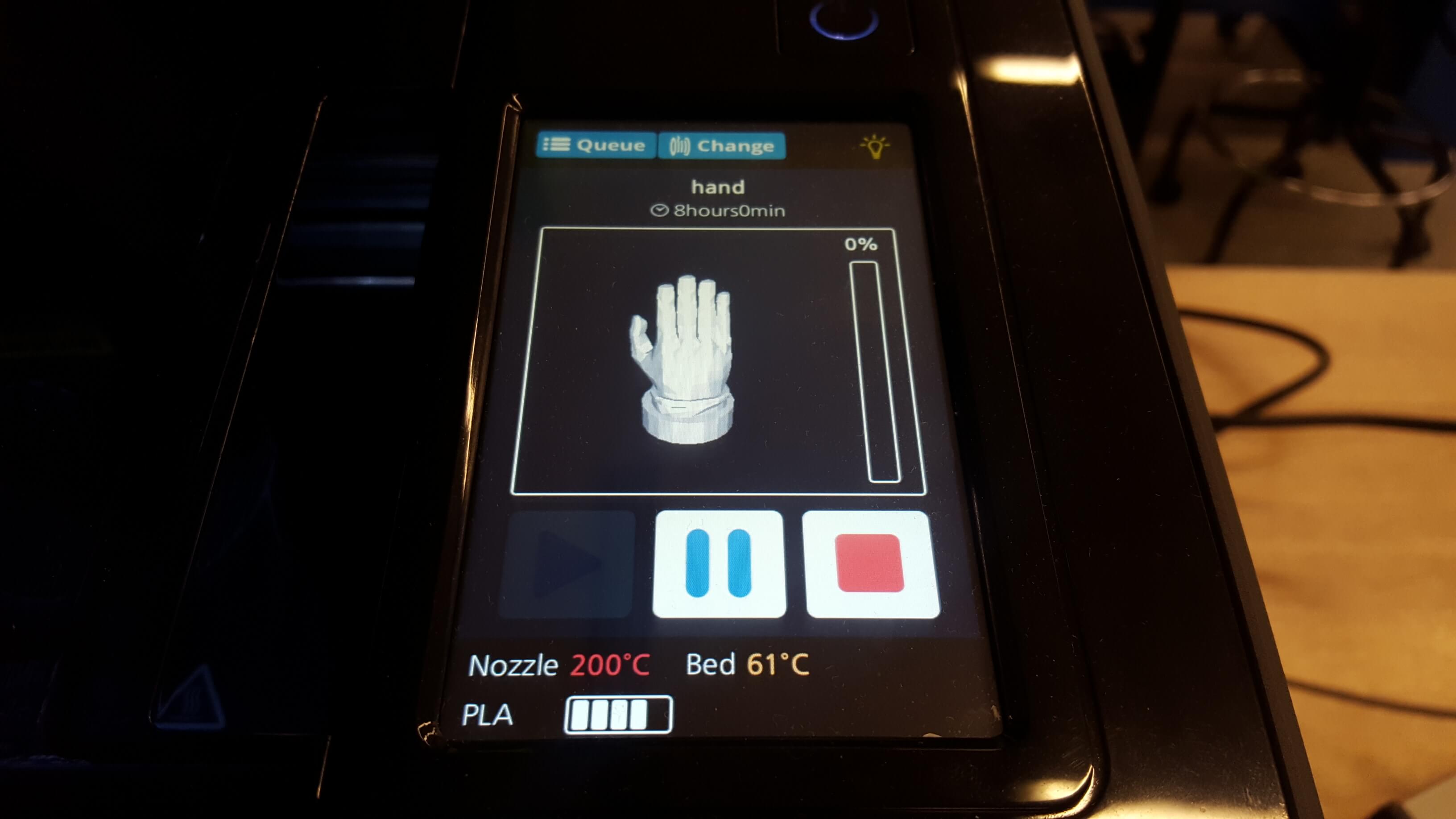
I 3D printed a big hand and a small hand for the ukelele and pic stands.
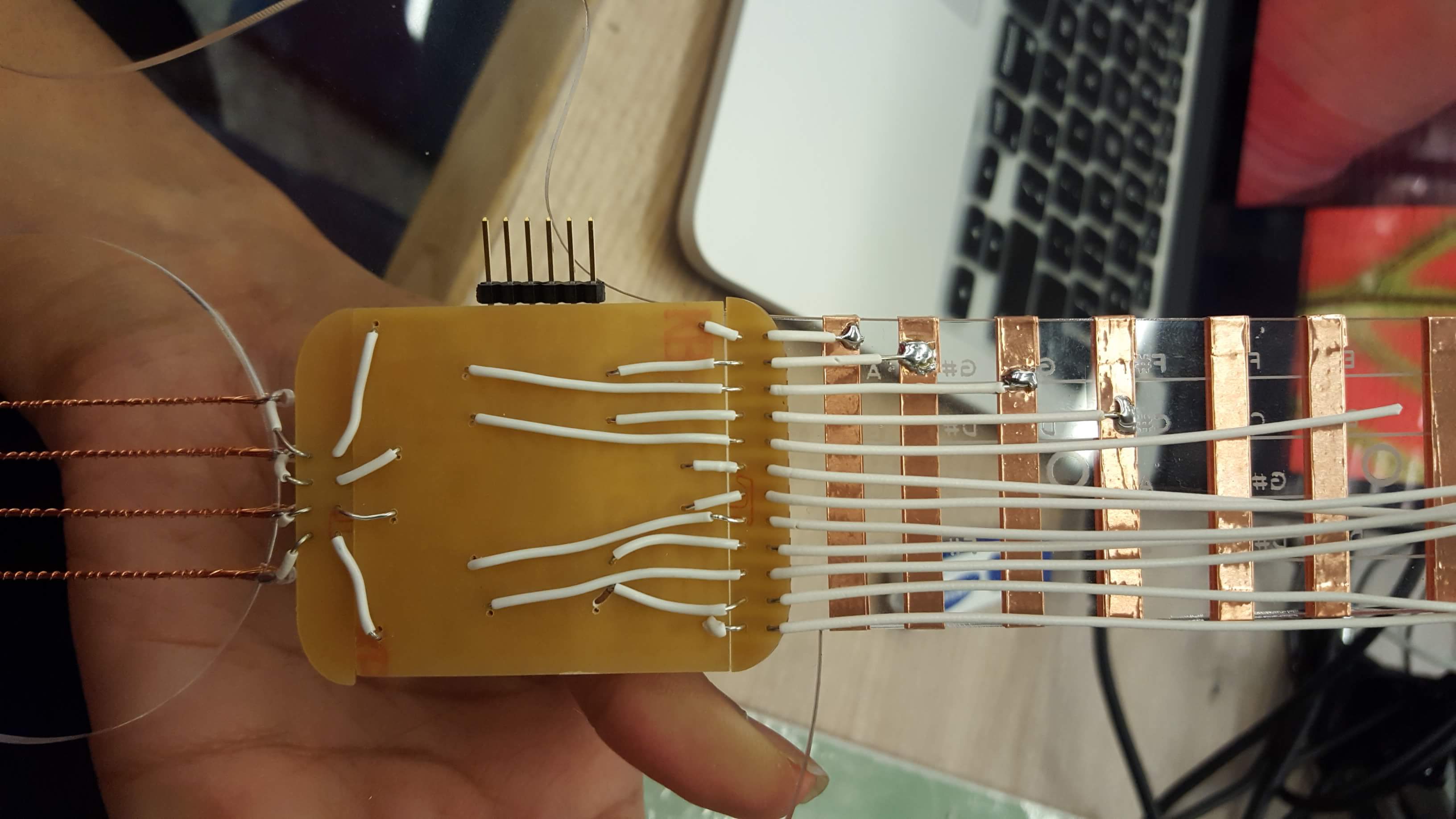
I tried to redraw the board Matt Keeter made to better suit my own design and move around some pins to accomodate the places where I wanted connections instead but struggled a lot with this - laying this board out is very hard to do without needed to compact certain areas and connect them with 0 ohm jumpers. I decided instead to make my own breadboard to clean up the wiring for the uke...
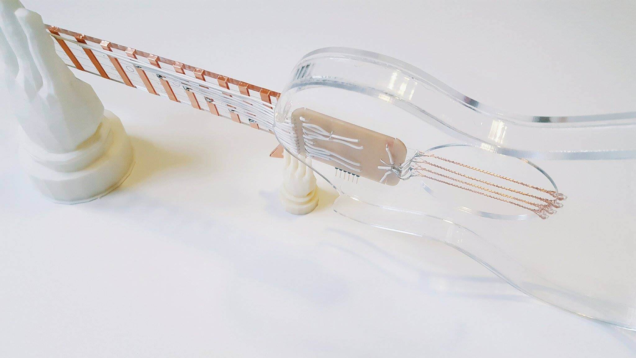
You can see what I mean here - theres a series of vias cut into a small strip here where I soldered short wires from the board to these parts, and then soldered the other holes out to the rest of the instrument now that they were all aligned well.
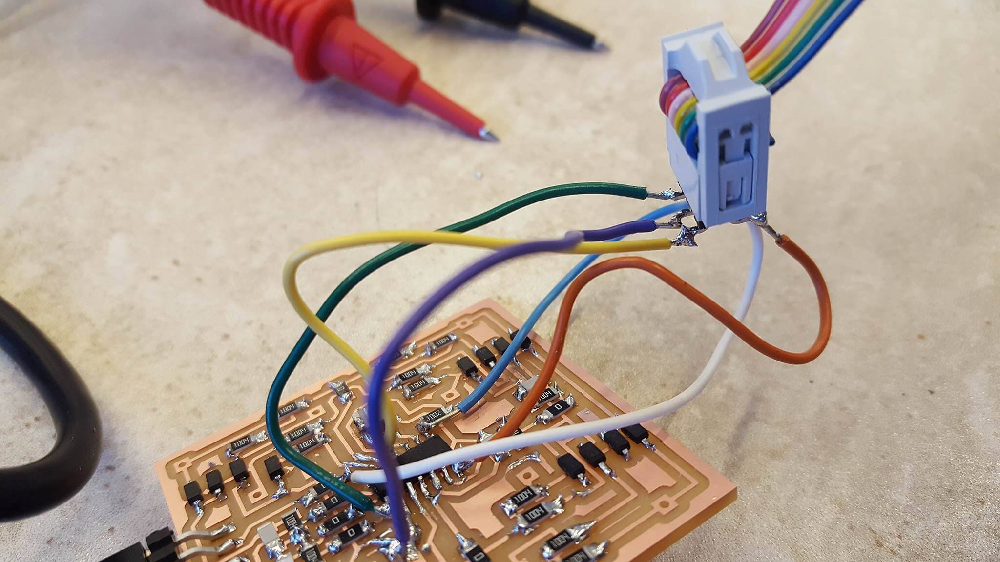
I assembled the wires to the uke together here! Now for the last step - to attach this to the uke. I took a pivotal step here before continuning to make sure all connections were good with a multimeter since adjusting anything after this step would be extremely difficult. I was also disappointed that every time I plugged my device in, the readings from the serial port were inconsistent every time I removed it and plugged it back in. More on this later in application development.
When assembling the wires to the copper strips, I wanted to limit contact of the soldering iron to the copper since I did not insulate the strips for heat (it would ruin the aesthetics). To resolve this, I tinned the tips of the wire before I applied heat to the copper so that heat would transfer faster.
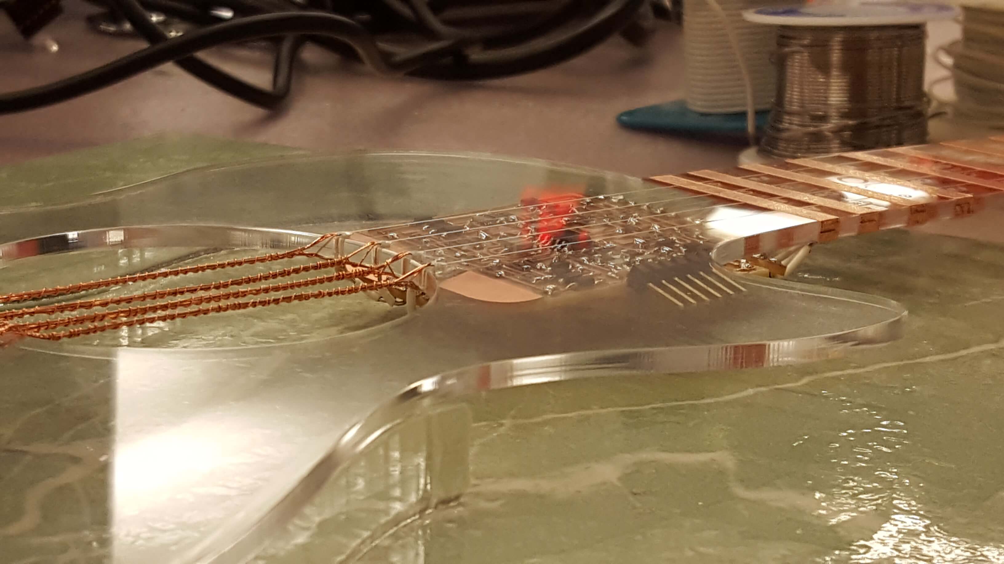
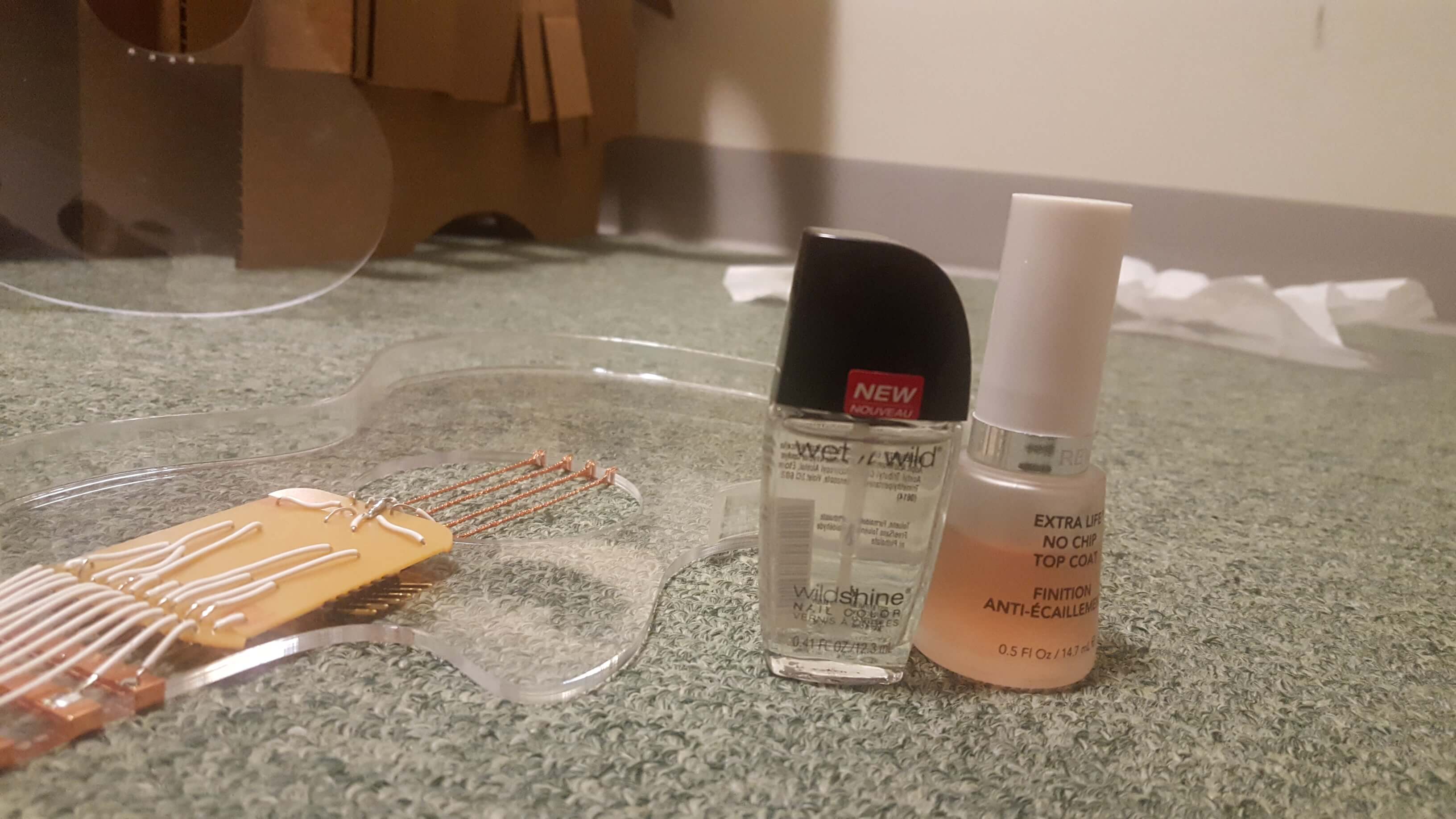
I laser cut a strip of 1/2 inch acrylic to function as the side walls of the ukelele to encase the electronics and make it feel more 3 dimensional.
I assembled those to my uke with clear nail polish - I would need a fume hood to use other stronger bonding glues so this to me was a better option temporarily. I will go back and fortify these bonds after the project, but this was a solution that functioned fine in this case.
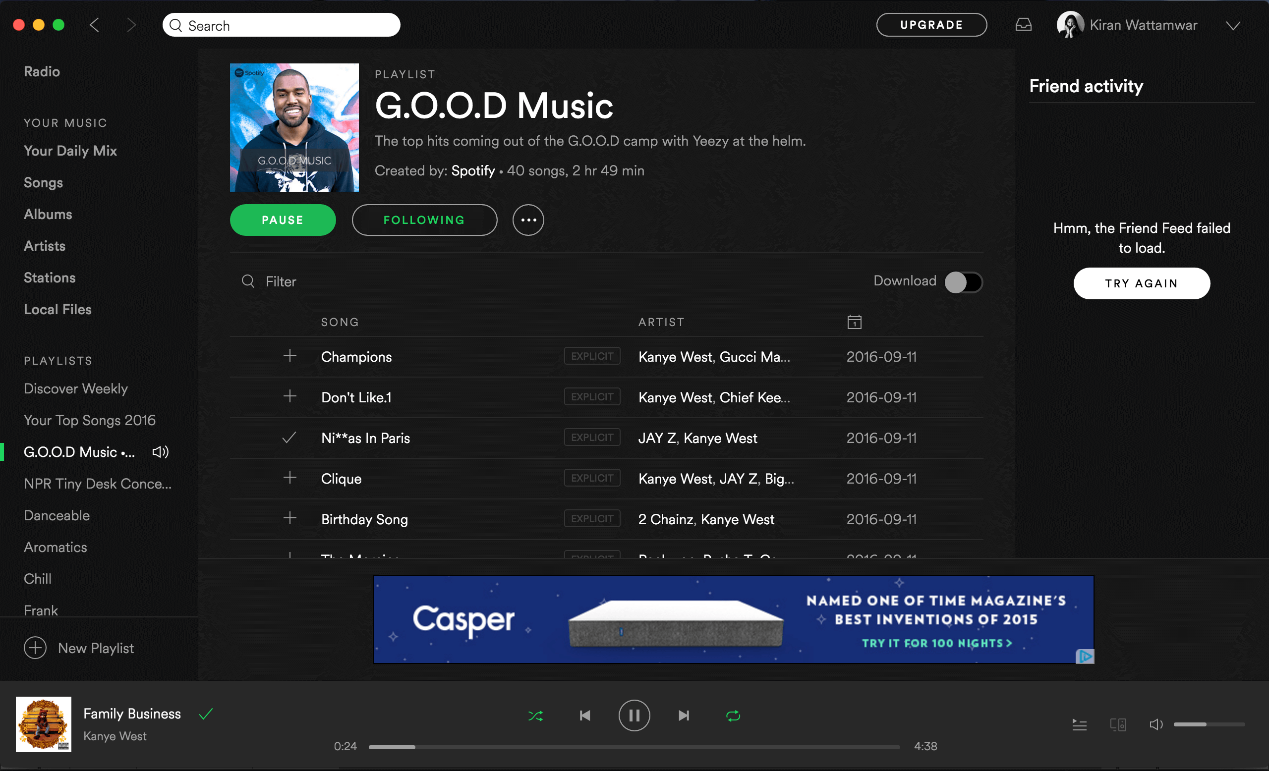
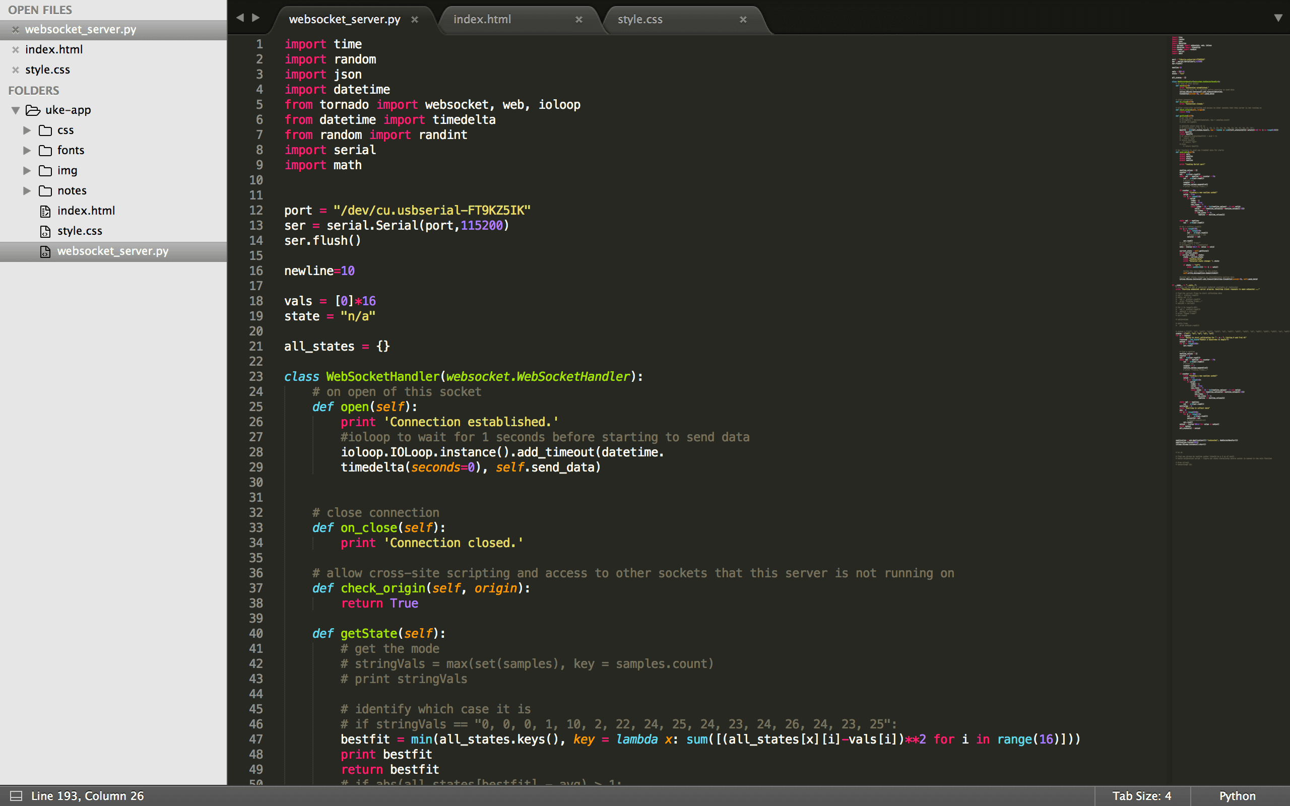
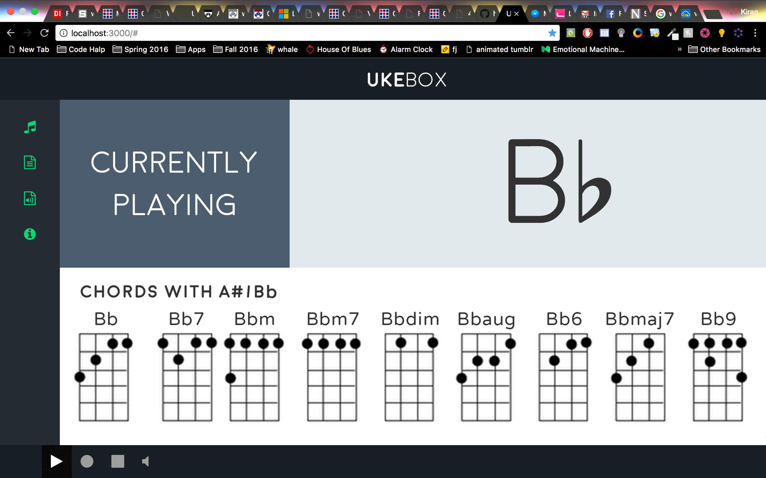
I was inspired by Spotify for my interface - I wanted the experience of my app to be met with familiarity and comfort instead of introducing something entirely foreign. I also wanted to build in specific functionality to my project - the ability to see information about the note being played (related chords), and record a session, and also translate the session into sheet music. Those last 2 features are yet to be implemented but can easily be done in HTML5 with audio features and the fact that my site is aware of what notes are being pressed as they are (for sheet music). My design model was a web socket server in python that could read from serial, process the data, and send a message to a web socket that my website was connected to. I understand that this is not compatible with Internet Explore - maybe for a longer term project, that could be navigated better. But for now, this was a good way to mock up designs (I'm more comfortable in HTML for GUIs over Python). I also tried initially to build the entire software element in python alone - I had many problems getting SDL, PyAudio, PyGame and other common libraries used for playing audio in the process so I figured that solving these problems would not be as productive as spending more time on development towards the project (so shifting to JavaScript for support for that was an easier choice).
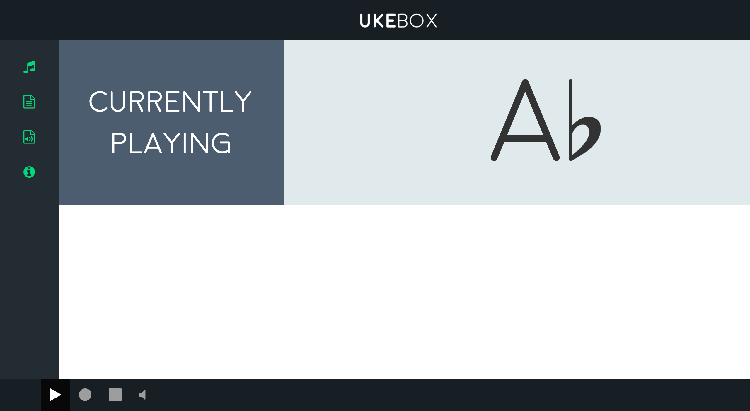
A progress pic of my site...
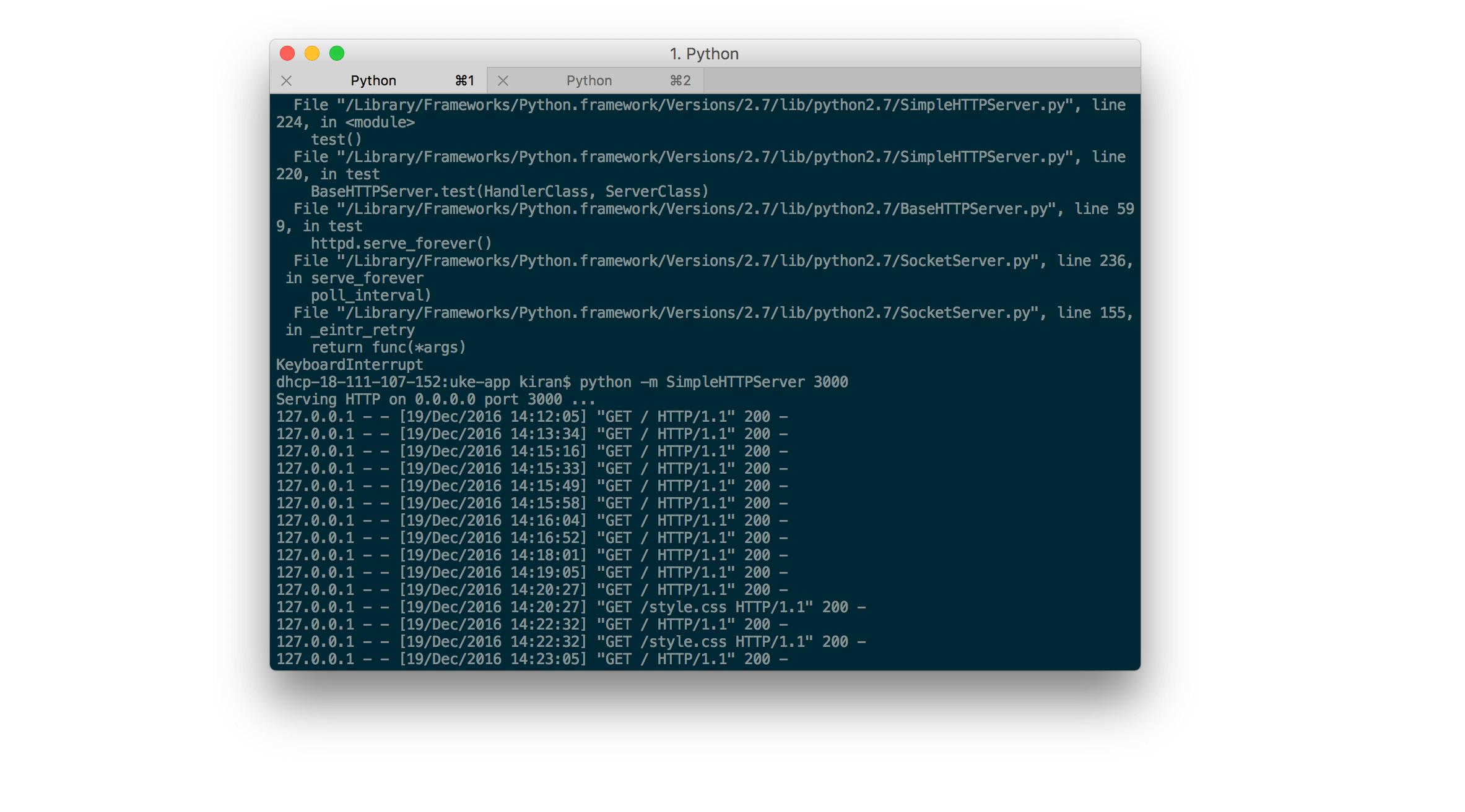
And the server running it...
This is probably the ugliest code I've ever written - I had a lot of issues with getting consistent readings from the serial port. I attribute this to maybe having the wrong baud rate here - tuning this would take a longer time that working on a hacky solution that could work around this. An example of inconsistency is the new line character that the microcontroller sent to serial would change in representation - sometimes it appeared as a "2" in serial, others a "10". And it would change in the middle of a session. I wrote a protocol that would search for the current newline, and if it could not find it every 16 serial readings (16 readings for 16 pins between every newline), the program would recalibrate to the device and try to find a new newline symbol. This inconsistency also caused difficult in reading the state of the pins - I decided to have users quickly calibrate the device before use to prevent using hard coded absolute expectations of readings to determine what is being pressed. Finally, I realized that the way I make contact with the device changes the readings - you need to press the pads a specific way to produce consistent readings which makes usability a little bit difficult but still manageable.
The final UI for the app!
This is the result of inconsistent contact with the pads on the ukelele - you can see that the notes arent always detected well and they are sometimes confused with the "off" state.
This is the result of good contact with the pads on the ukelele - please excuse the awkward pauses! 2 hands are limiting.