
Final Project
This is a combination of all the previous final pages as well as the documentation for the final push to develop the board. Most of the code is on the project GitHub.
The final iteration of my final project is a blindspot detector for my bike. I will be using radar modules to detect objects moving behind the bike. The blindspot detections will be displayed using a RGB LED strip to display the results.
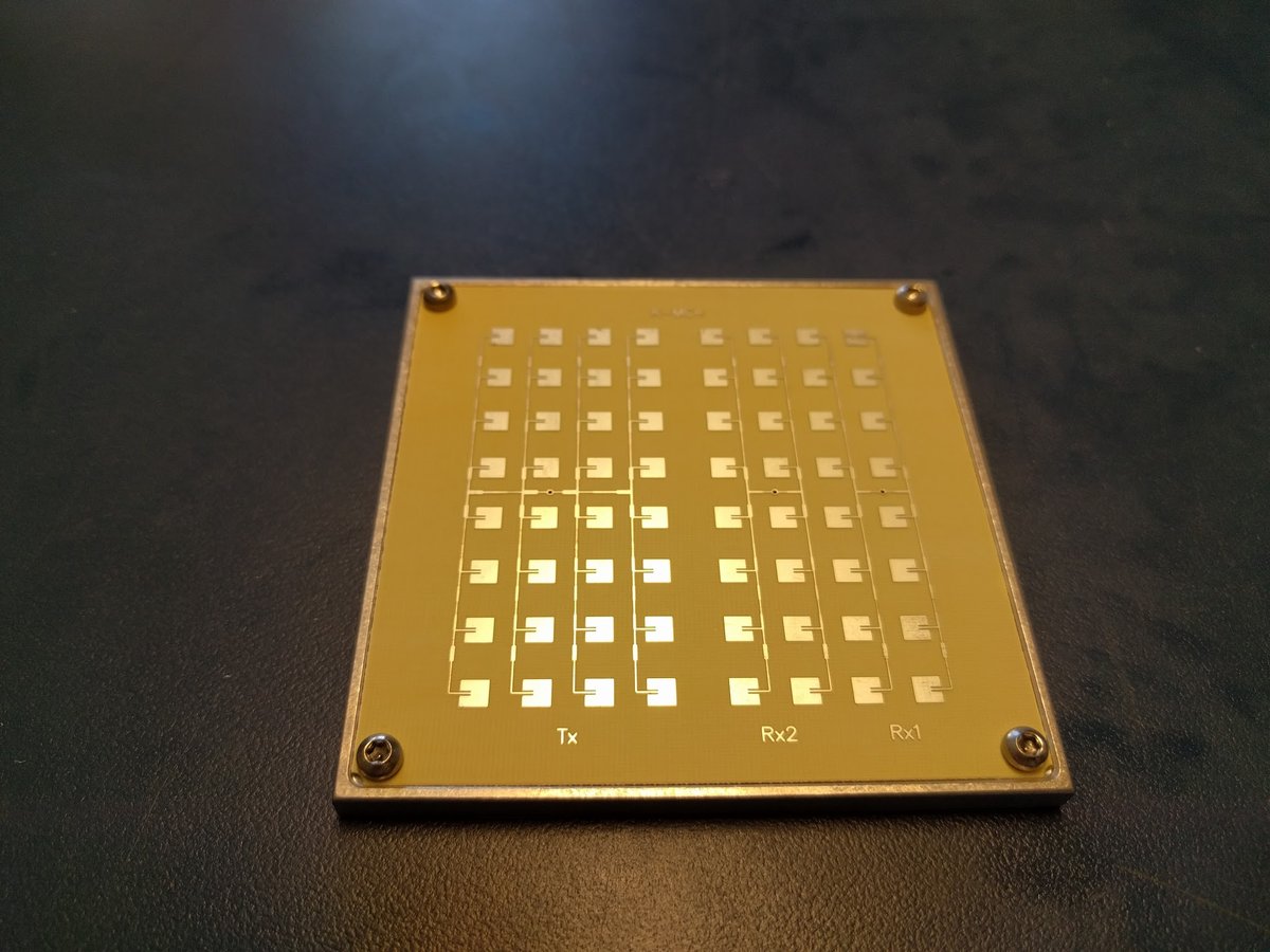 Big radar board.
The system is built around a RFBeam K-MC4 Radar Tranceiver. It is a 2 channel 24 GHz radar that is capable of being used in FSK, Doppler, and FMCW radar modes. I selected this radar because, in addition to providing radar ranging and velocity information, it provides the target angle. This is accomplished by a asymmetrically configured antennas that create a phase shift between the two channels.
In the end, I opted to focus on the angle and differential speed of passing vehicles as these are the most likely to provide useful information to the biker.
Beyond the electrical componentd, the system had to be mounted to my bike in a way that protected it from the elements and didn't get in the way of it functioning.
Part of this project involves extensive signal processing. I initially had thought about running an FFT on an ATMega, but after some reading and a few tests, I quickly realized that that was an unrealistic goal as the ATMega doesn't have a floating point unit so it can't do floating point math (useful for FFTs).
On Neil's advice, I looked into DSP filters on the ATMega to determine phase; However, after some simulation, I was unable to get the phase and frequency resolution necessary.
 The block diagram of the final signal processing setup. The ATMega gets
the 4 radar channels and converts the analog signal to digital values which are then sent over a
parallel interface to the Raspberry Pi where a block of C code converts
the data into a NumPy array and then an FFT is run on the data in Python.
The block diagram of the final signal processing setup. The ATMega gets
the 4 radar channels and converts the analog signal to digital values which are then sent over a
parallel interface to the Raspberry Pi where a block of C code converts
the data into a NumPy array and then an FFT is run on the data in Python.
Finally, I settled on connecting a Raspberry Pi to an ATMega to use the floating point capabilities to compute the FFT. This also allowed me to write the FFT code in Python which was very simple.

After realizing that I couldn't use Python to do the GPIO reads, I opted to write a extension to NumPy in C. Using C allowed me to scan the IO ports more frequently and never worry about missing a bus clock cycle. Once I had written the extension, I could simply call numpy.input.get_data() and it returned the data in an array.
 Milled board with bodge wires.
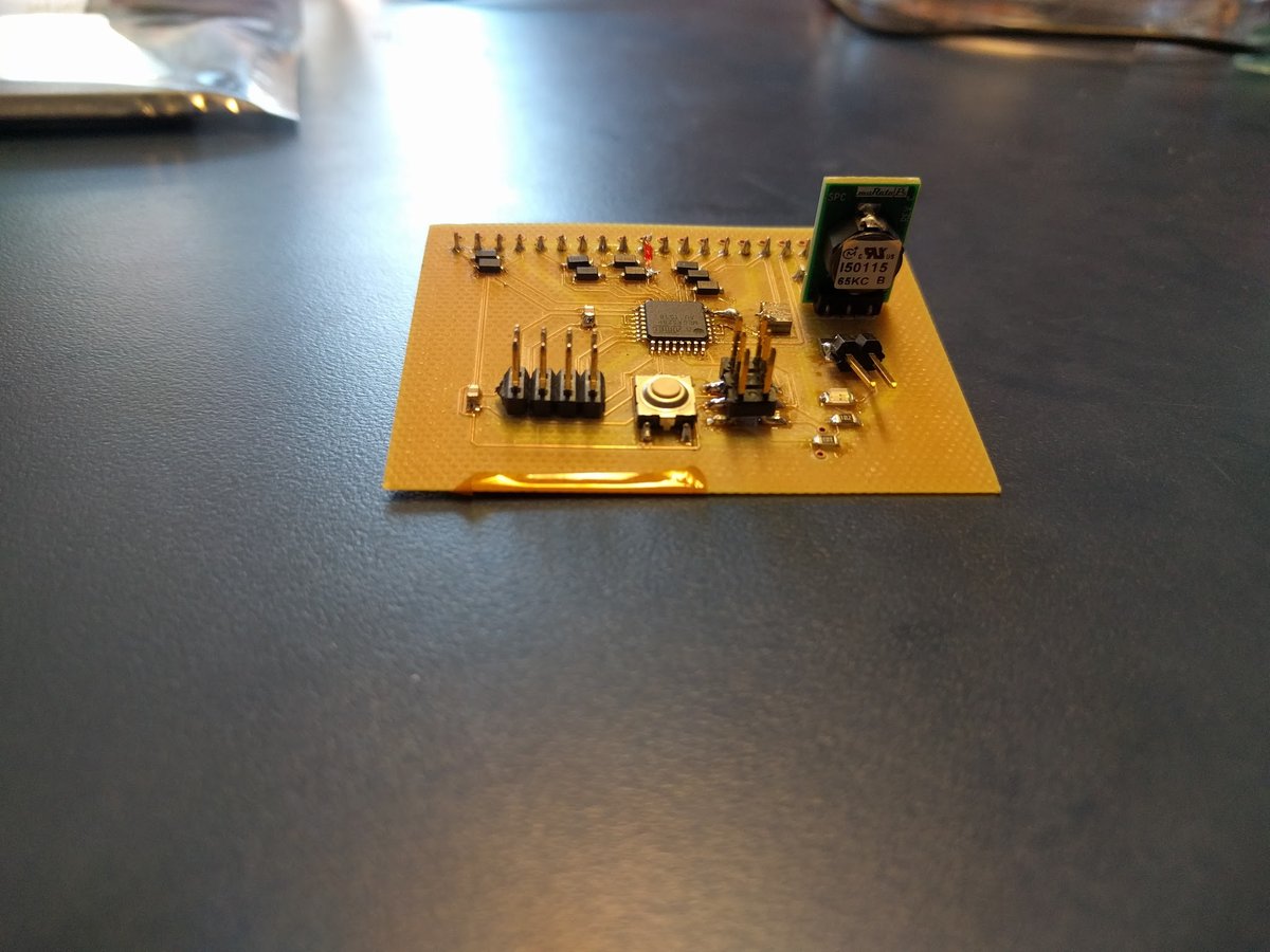
 Board for radar.
 Radar being tested with a oscilloscope.


The K-MC4 does not have any sort of protective facing so I needed to fabricate some sort of cover for it. The Radome design I came up with mates with the RFBeam mounting plate and has untapped holes which can be tapped with sheet metal screws. I followed RFBeam's own application note on Radome design to select the proper materials. Based on the materials table, I opted to 3D print an ABS Radome on a Stratasys Dimension Elite. However, the print separated from the bed mid print so the Radome was unusably warped out of shape.

I then decided to use the Sindoh 3DWox to print the same Radome in PLA which has similar dielectric properties to ABS.
 The mounting plate screwed into the Radome.
 Testing the Radar with the Radome mounted.
I then laser cut a box out of 1/4" acrylic scrap to use as the enclosure for the Raspberry Pi, ADC board, and Radome itself. This came together quickly using a case generator tool. After being sure I was satisfied with the cardboard version, I cut the acrylic.
To mount the box and LED strip to my bike, I wanted to make casts in the mold I had made in Week 7. However, my mold seems to have gone missing and as the milling machine was tied up with milling circuit boards and other projects I just printed two mounts and glued them onto the back.


After assembling the box, I got the entire system running off my bike light battery pack which is just comprised of 4x 18650 Lithium Ion batteries. I was in the process of adjusting the sensitivity of the system when I inadvertently shorted the ADC board which I did not have time to remill.
I made the LED display board using an ATTiny to display the direction of the vehicle in a simple way that would not be too distracting while biking. Since I was using an ATTiny 45, I opted to Charlieplex the LEDs to put 6 LEDs on three pins.
 LED Board
I then encased the LED board in SortaClear-37 which protected it from the elements. However, I was using old SortaClear which cured much faster then I expected. This resulted in a very bubbly mold.
 The SortaClear was almost fully cured by the time I was degassing a second time.
 The result of incomplete degassing.