| Back to Index |
Sorry! Not many interesting pictures for the week, I was digging in to code, and didn't find it particularly photogenic. My goal for the week was to modify Neil's RGB code to work on my step-response board from week 8. Fortunately, and unlike during week 8, modifying the code to work on a T44 instead of a T45 wasn't too much of a headache. The CLKPR bits are the same, and everything else in the code just deals with PWM and pin assignments.
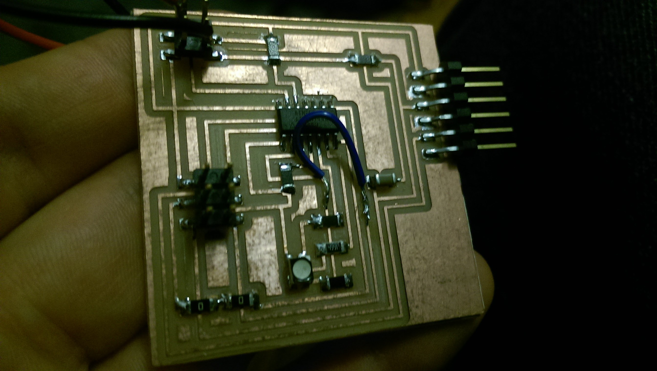
I realized that not all the pins I had put my RGB LED on during week 8 were capable of pulse-width modulation (PWM), which Neil's code uses to fade the brightness of the LEDs in and/or out. I searched for "PWM" on the ATTiny44 datasheet, and in the pin descriptions, found the following quote: "The OC1B pin is also the output pin for the PWM mode timer function." Only four of the pins (PA5, PA6, PA7, PB2) had this phrase. Fortunately, two of my LEDs were alread on PA7 and PB2. I rerouted the third LED to PA5 on Eagle, but realized it'd just be easier to modify my existing board. So I chopped the trace leading to the wrong pin (PB0), and added a jumper connecting to the right one (PA5):
Next challenge: modifying the macro definitions in Neil's code to work on my board. In Neil's code, every LED is on the B register, so the following works:
#define led_port PORTB
#define led_direction DDRB
#define red (1 << PB1)
#define green (1 << PB0)
#define blue (1 << PB2)
However, on my board, some LEDs were on the A register, some on the B. I redefined the port and direction as follows, and was careful in subsequent code about which color I was referring to, and used the correct led_port and led_direction:
#define ledgb_port PORTA
#define ledgb_direction DDRA
#define ledr_port PORTB
#define ledr_direction DDRB
#define red (1 << PB2)
#define green (1 << PA5)
#define blue (1 << PA7)
I wanted to figure out how to have the color Orange (R=255, G=165, B=0) fade in and out, but didn't have the time or mental energy to figure out how to keep a R:G ratio consistent during PWM. I resolved to not solve that mystery this week, and to leave it for December, when I'd have more mental bandwidth available for decoding and recoding the coding. Yellow, however, seemed easy enough: full Red and full Green, no Blue, so I added it to my code.
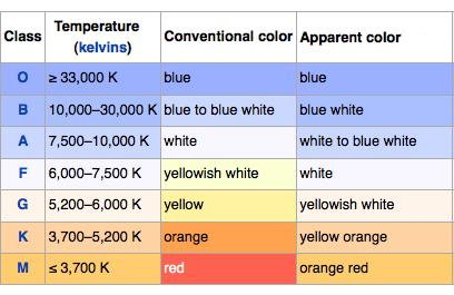
I swapped some colors around in Neil's code, so the color progression could mirror that of stars as their temperature increases: Red --> (Orange) --> Yellow --> White --> Blue, per the below image:
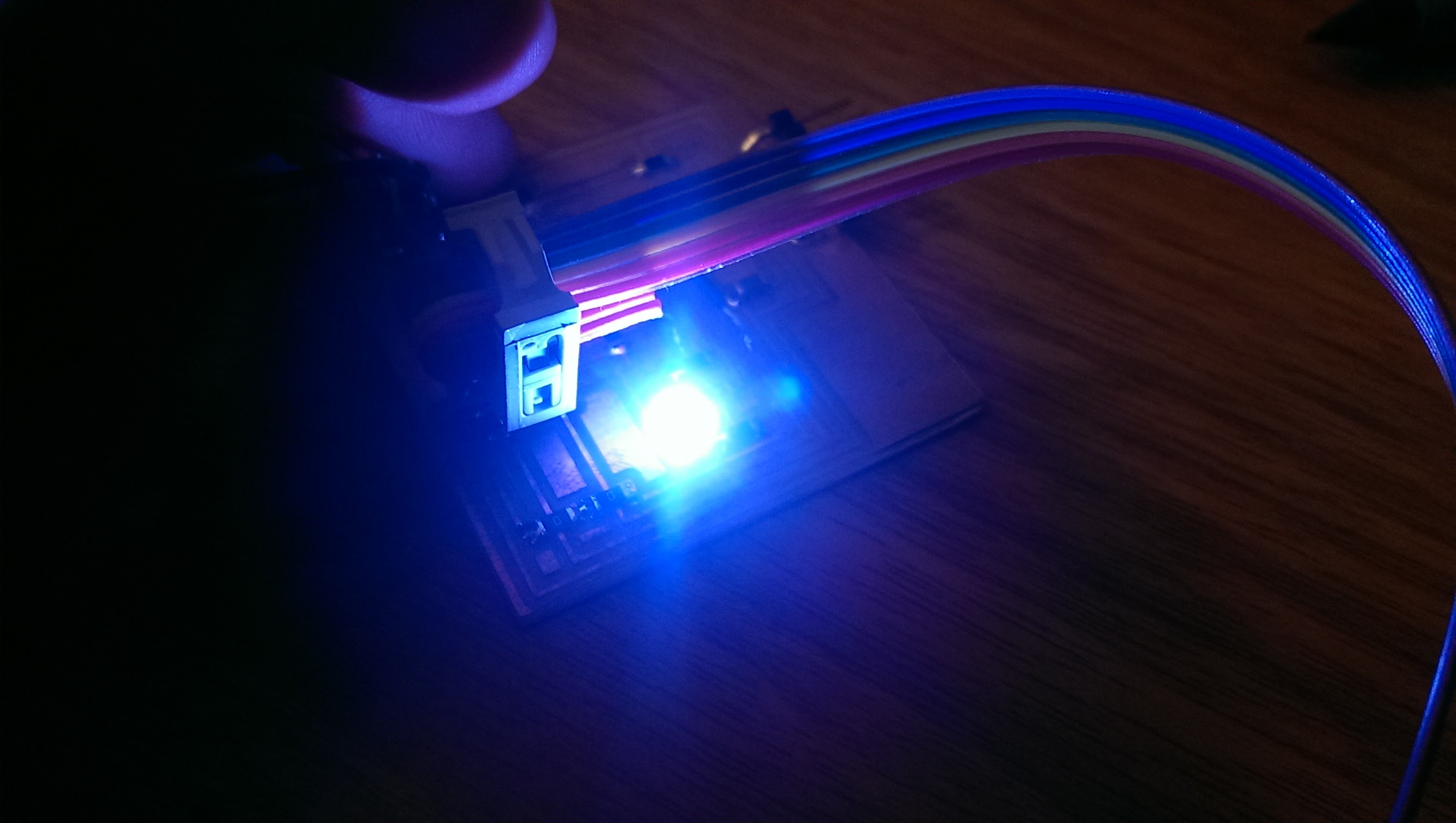
I plugged in my programmer, and tried to compile my c into a hex file. Error. In the make file, I had remembered to change from the T45 to the T44, but forgot to change the "PROJECT=" name at the top to match my c code file name. I changed that, and the command 'make -f file_name.make' generated a beautiful .c.hex file and a .out file. I flashed the code to my LED board, and was greeted by pulsing colors!
Just so I have them all in once place, I'm including the magic words to type into a terminal to successfully program a T44 with my T44-based usbtiny programmer:
avrdude -c usbtiny -p t44
(This checks to make sure everything is talking nicely.)
Next, navigate to where your c code and make file is living and type the following, which generates the .c.hex and the .out files:
make -f file_name.make
Finally, flash the code to the board in question:
avrdude -c usbtiny -p t44 -U flash:w:file_name.c.hex
I was getting colors, but they were a little wonky. Green was showing up strong, and I had no green in my code. I was expecting blue, but blue was nowhere to be seen. Logan, in the Harvard section, suggested I use the oscilloscope to check out what was going on. Together, we identified which pins were PWMing when. We then ran power across each LED, to see if blue was showing up. It was, but VERY faintly. Using a multimeter, we checked to make sure the resistors were operating correctly. R and G both had 1k resistors, as they should. Blue's resistor wasn't showing up, so we changed the scale on the multimeter. Turns out I had used a 499k resistor instead of a 499 resistor. Two minutes later, with the wrong resistor removed and the correct one soldered on, Blue was shining bright.
While using the oscilloscope, it had occurred to me that, maybe, just maybe, I might've assigned the wrong pins to the wrong color. Sure enough, I had. I made those changes in the code (reflected in the code posted above).
The colors still weren't doing what I expected them to be doing. The RGB is on a common anode, meaning when pins are LOW the corresponding LED is ON. As an experiment, I reversed all the "clear" and "set" commands in the code. Instead of colors jumping on and fading out, they faded in and jumped off, as intended. There were a couple other oddities in the RGB behavior - for example, when first starting up, I told it to cycle R, G, and B up and then off, in that order, to make sure I had everything assigned correctly. I did. But it would only do RGB at the start, and for every subsequent loop of the program, skipped those three. I'm not sure why. But, I figured out that I could program my board using my programmer and my computer, so I'll fiddle with the colors at home, to try and understand them a little bettter.