Final project: Camera gimbal for iPhone
Final product
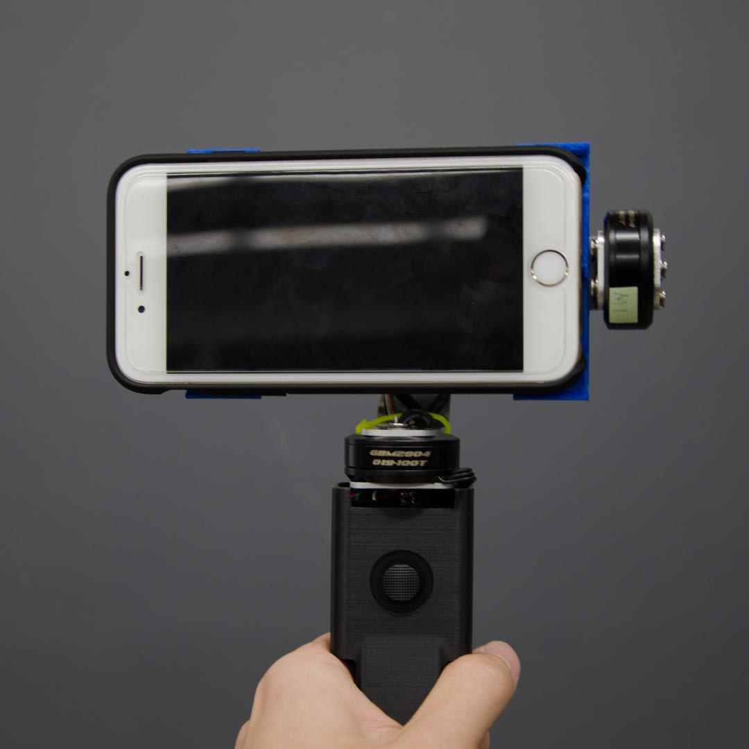
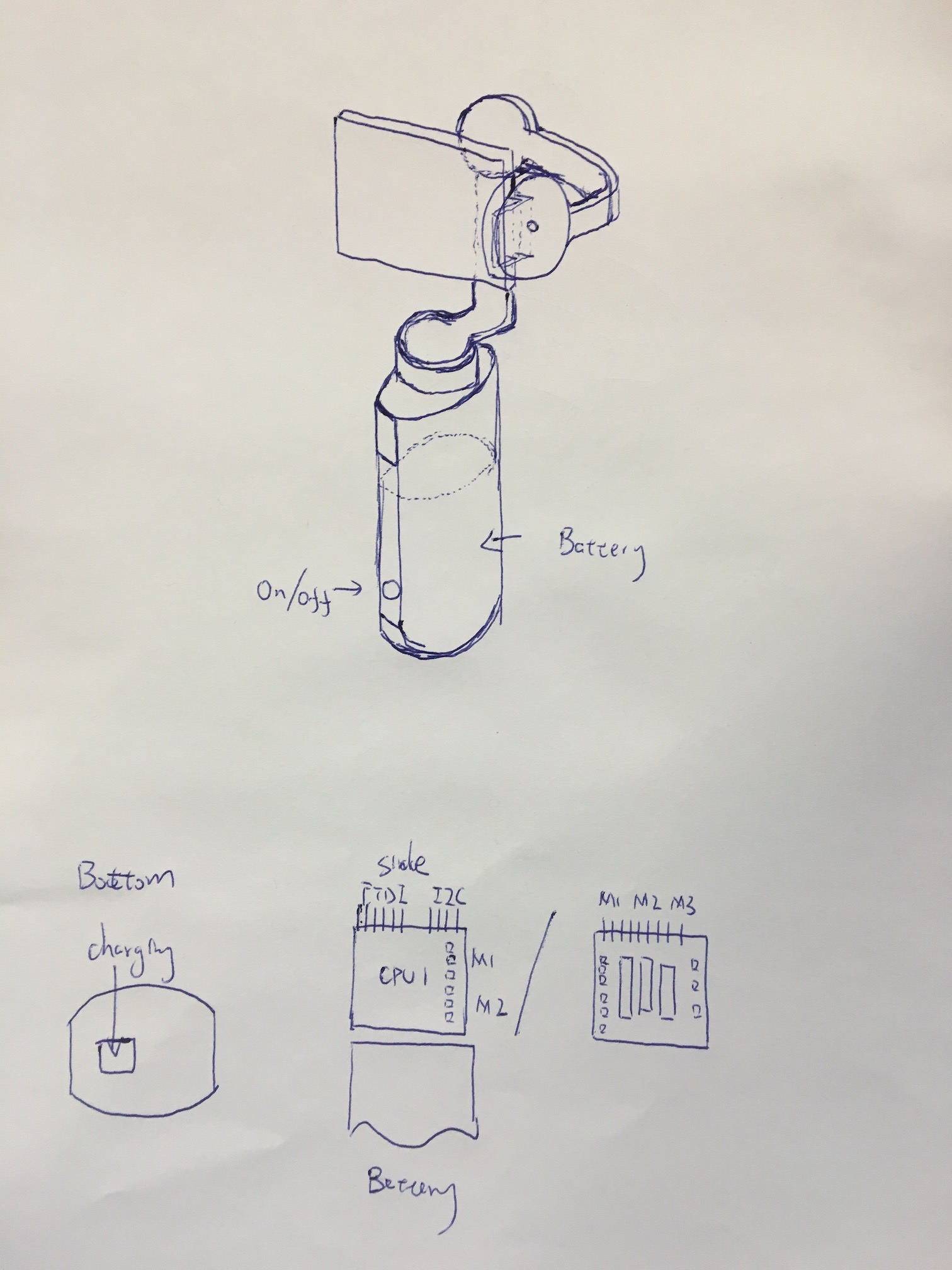
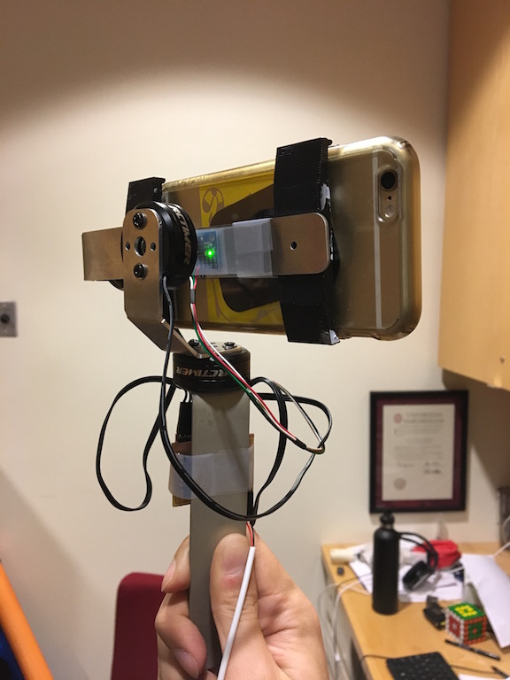
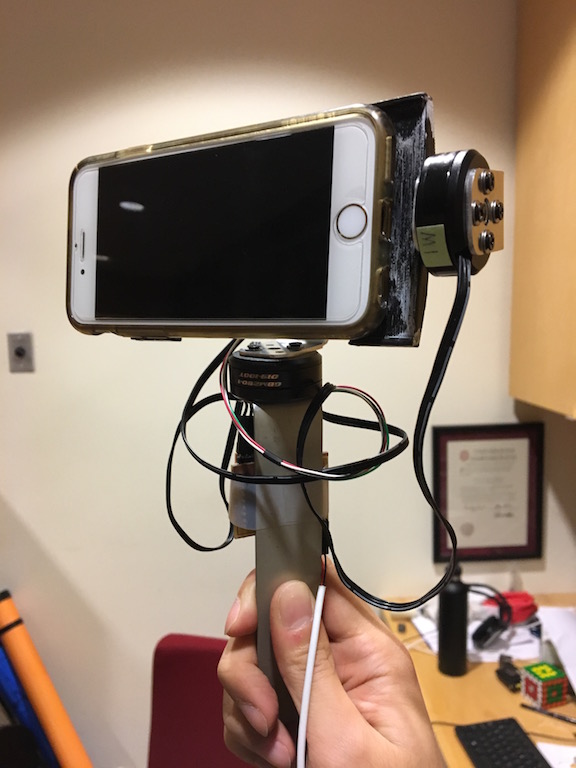
This is a iphone camera stablizer which stabilize on all three axis, it damps 80-90% of the vibration. It is based on accelorometer and gyroscope feedback and can pan with a joystick. Iphone hold onto the gimbal magnetically and can be easily attached or detached. This stablizer can be used to take smooth videos, long exposure light trails and hyperlapse videos with handheld.
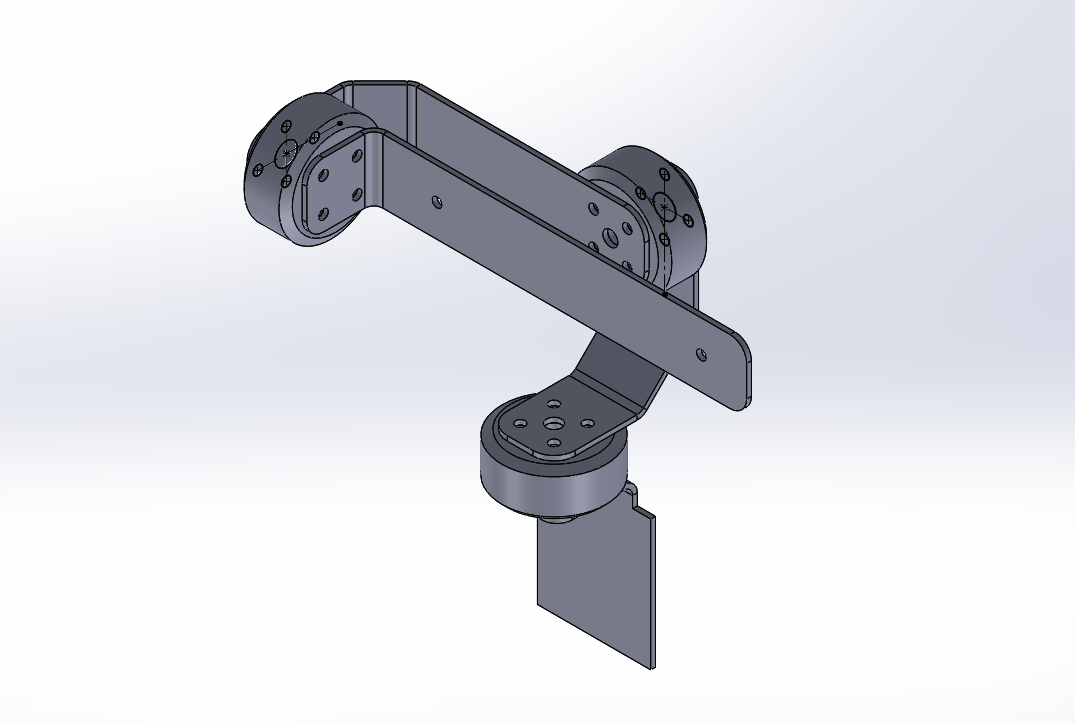
Architecture and components
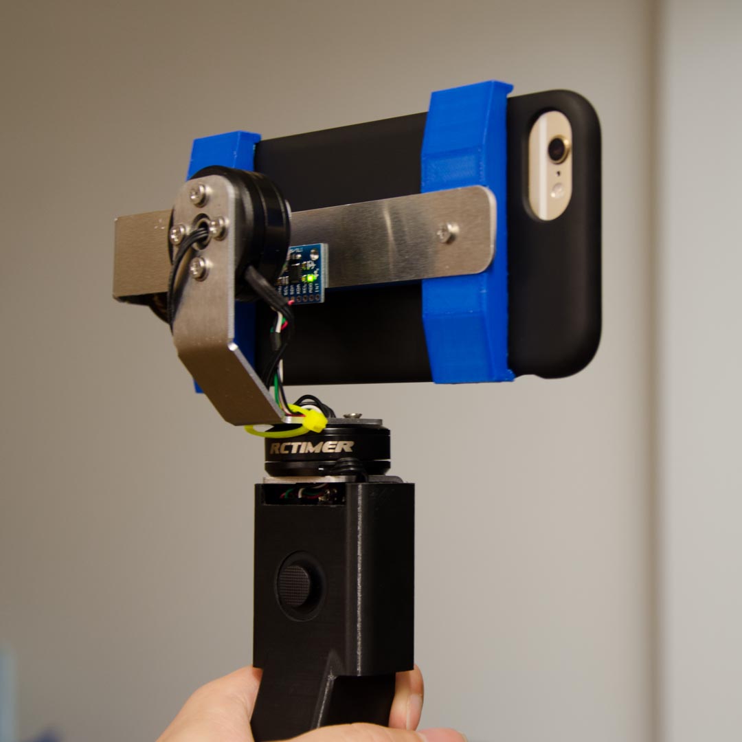
It has a 6axis inertial sensing unit fixed on the supporter of the phone, which detect rotation in three axis and the gravity direction. The signal is read by one ATmega328p microcontroller through I2C interface (Week8 ‐ Input device). There are three brushless motors in three axis which compensate the motion of the base (Week10 ‐ Output device, Week11 ‐ Interface programming). Two of the motors are controlled by the microcontroller (MCU1) which read the gyroscope. The last motor is controlled by second microcontroller (MCU2) which access the gyro data from MCU1 through serial interface (Week12 ‐ Network). The feedback is controlled by PID implemented in the microcontrollers. And the device is powered by a 5V battery bank, accessed by USB. The aluminum frame is designed in solidworks sheetmetal, cutted with tabletop Shopbot then shaped with metal bender. The handle and phone holder are designed in solidworks and 3D printed. A joystick is added on to add pan ability. It's based on two potentiometer and is read by ADC conversion to MCU2.
Below are close-ups of each part and component.
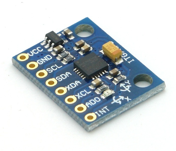
6axis in inertial sensing unit, available from Amazon for about $3.
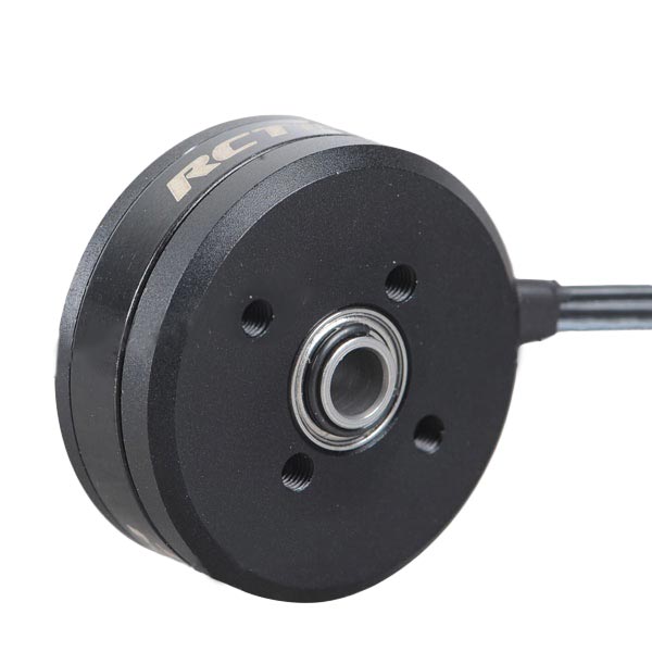
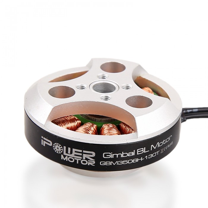
brushless gimbal motor, available from Banggood for about $13.
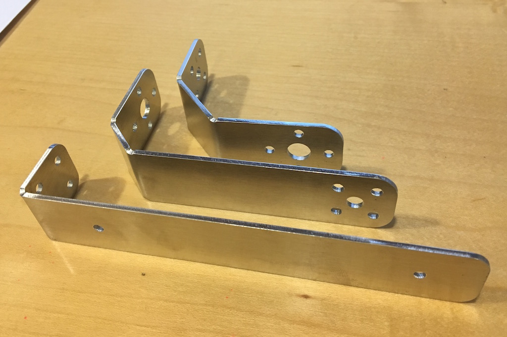
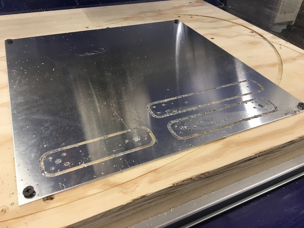
The frame is made from 0.064' aluminum sheet which should be available anywhere for about $10. The back is purposely designed to partially cover the handle due to heat dissipation requirement of the H-bridghe chips.
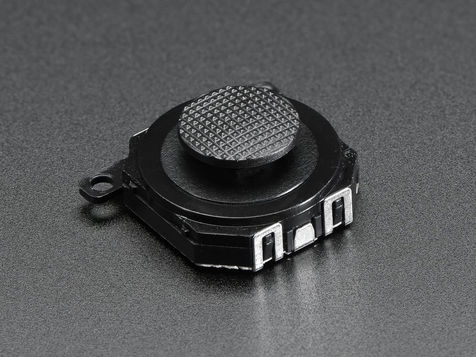
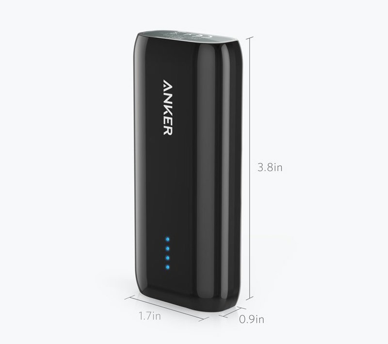
The battery are common lipstick size power banks. And the joystick is available at Adafruit for $3.5.
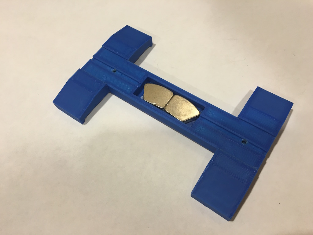
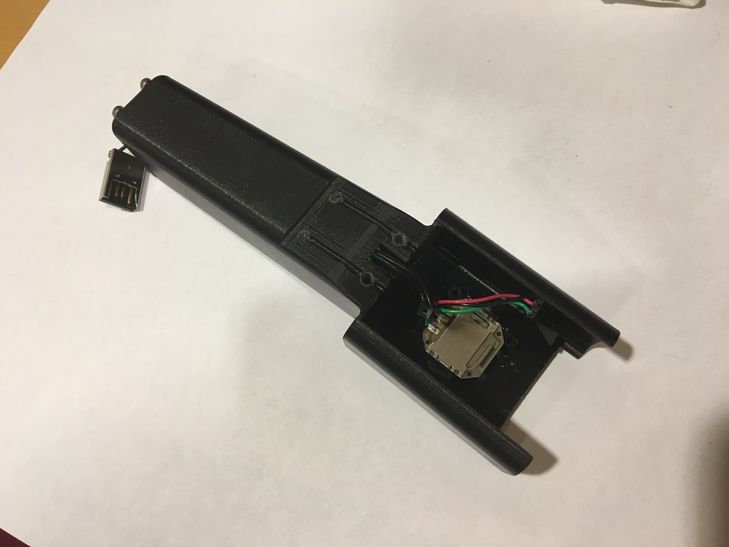
3D printed phone holder with magnet on the back of the holder.
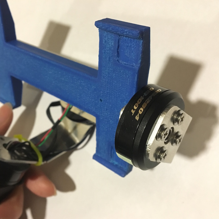
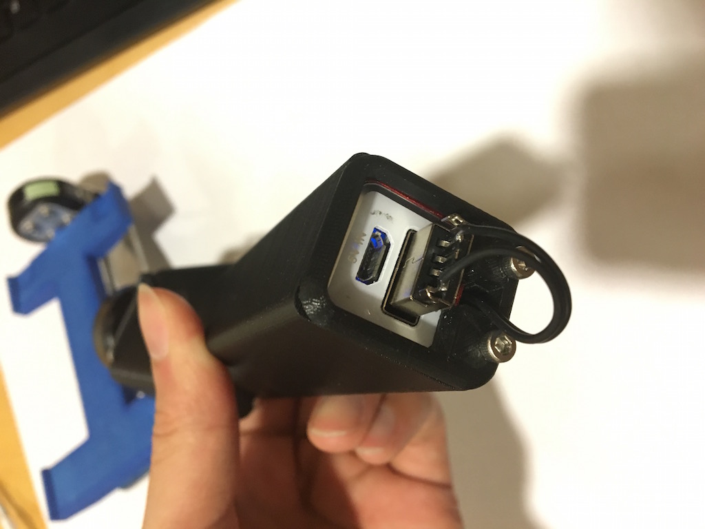
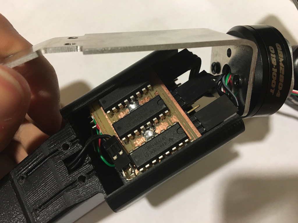
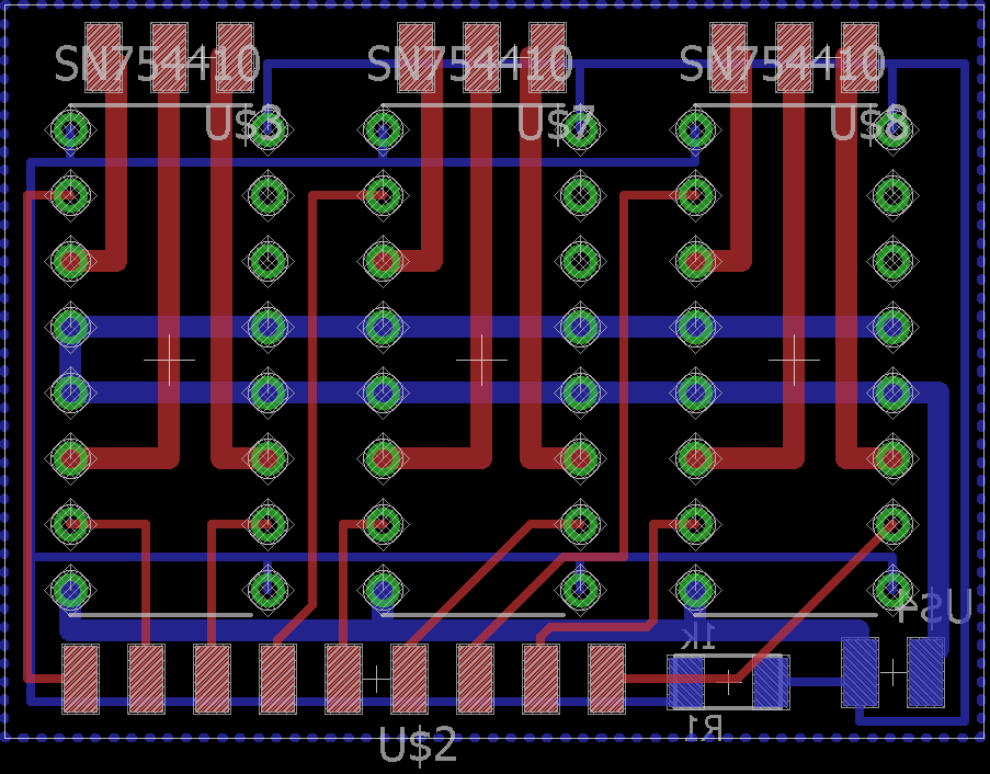
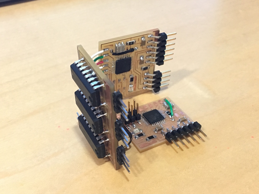
3D printed handle. And the connection with the board and aluminum frame. Also shown in the picture are three IC of quadruple half-bridge: SN754410. Note that the half-bridge IC are directly contact with aluminum for heat dissipation, as it get really hot in operation.
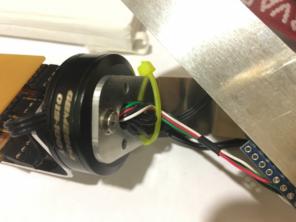
To tidy the wire and offer as much rotation degree as possible, I run the wires through holes of the motor shaft as shown here.
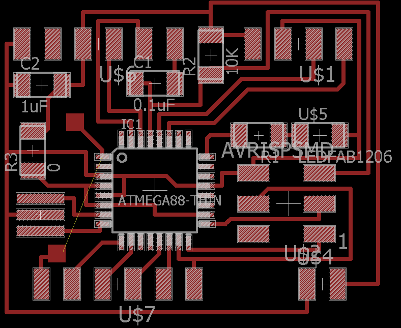
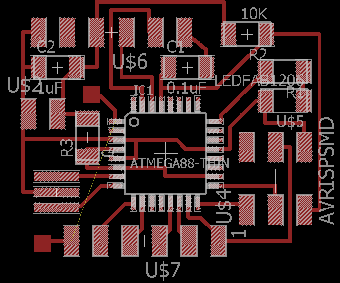
Finally the control boards, are designed in eagle, one double sided board for driver and two single sided board for microcontrollers. The ISP header are removed after burning boatloader to save space.
Control algorithm
The MCU1 read from the inertial senser about every 1ms. And every time it read it will set new movement for the motor. If it sense a rotation in X axis positive direction, it will tell the motor controlling x axis to rotate backwards. In the control algoerithm, I used P term and D term for gyroscope and only P term for accelaration. The D term is not really needed as the gravity detection essentially serve as the D term of the gyro. Take the Y axis as an example.
	feedGyroY[2] = feedGyroY[1];
	feedGyroY[1] = feedGyroY[0];

	feedAcZ = AcZ*4.0/65536.0*1048.0*7.0/3.14/2;
	feedGyroY[0] = (GyroY+453.0)*500.0/65536.0*interval*sensormotor/1000000.0*1048.0*7.0/360.0;

	setpointM1 = -(feedAcZ*0.02+feedGyroY[0]*30+(feedGyroY[0]-feedGyroY[1])*70;
	stepsM1 = (int) setpointM1;
	if (abs(stepsM1) >= sensormotor) speedM1=1;
	else speedM1 = sensormotor/abs(stepsM1);
The stepsM1 set how many steps the motor 1 will need to move. And the P setting for GyroY is 30 while D is 70 and P term for Accelaration in Z directino is 0.02/ The existence of theis acceleration term will try to keep the iphone upright. The speed is choose to make the movement most smooth. And the detail of how to drive this brushless motor precisely step by step can by found in Week10 ‐ Output device, Week11 ‐ Interface programming
The entire code for the microcontrollers can be found master and slave.
Design and development history
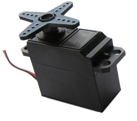
I plan to make a three-axis gimbal for iPhone camera using brushless motor. A gimbal can stablize the camera and reduce camera shakes. It can help with long exposures without bulky tripod and can enable smooth video filming. This kind of 3-axis gimbal cost about $250, however if I make it myself I can make it for arount $50. There are two ways to make a gimbal, using servo motor or brushless motor. I decided to go with brushless because it is more compact and graceful as servo motor are irregular shapes. However, the brushless motor is harder to use and need more sophisticated control systems. After some investigations, I found these two brushless motor suit for gimbal uses: iPower GBM3506H-130T and RCTimer BGM2804 100T (right two images). They have more windings (130 and 100 turns) and larger inner resistance than regular brushless motor which designed to run fast but not supplying a lot of touque. These gimbal motor can't run very fast but supply very large torque at small current so we don't need a buck converter to step up the current. The cost is around $15 each and I need three of them.
For sensoring the gravity and angular velocity, I need a IMU (inertia measurement system). It should able to detect both down direction and if the frame is rotating from side to side. I found this 6axis IMU with 3axis acceleratometer and 3axis gyroscope: Kootek GY-521 MPU-6050 module based on MPU-6050 IC. It cost about $3 and communicate with microcontroller through I2C interface. I was able to read the accelaration and rotation speed from this IMU in the week of Input devices.
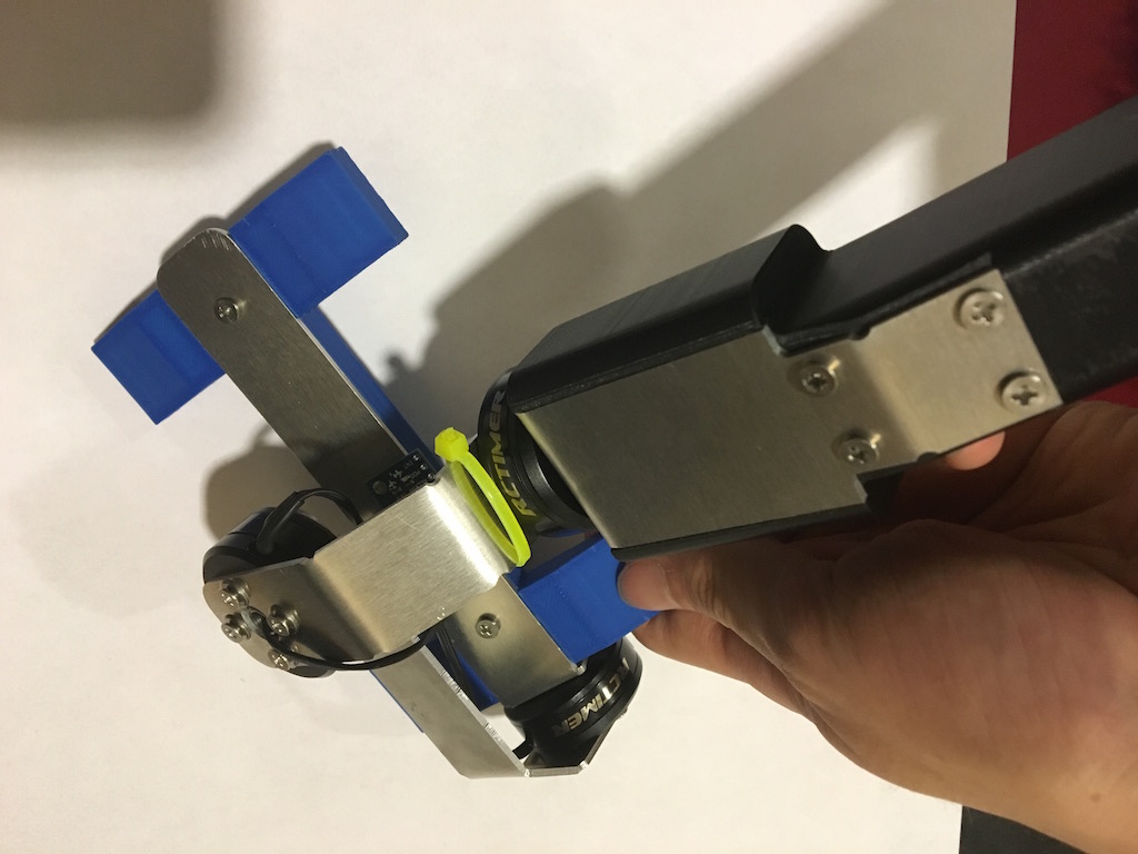
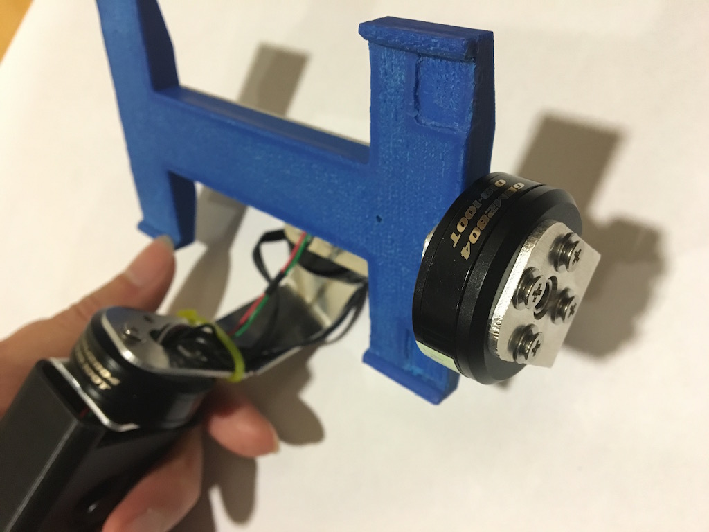
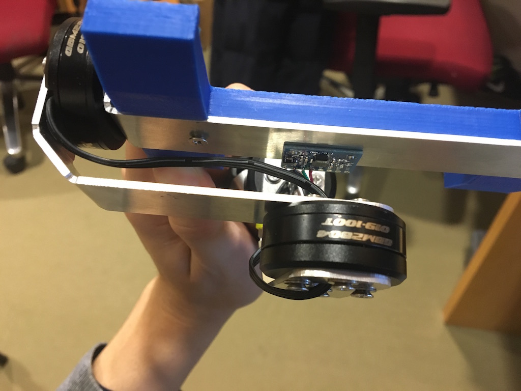
For driving the motors, we need triple half bridge which connect to the PWM output from the microcontroller. I used SN754410 quadruple half-H bridge to drive the output. Most information of driving the motor is in Output devices week. And I calibrated the motor in the week of Interface programming. Then I made a structure (shown below) to test the stablizing in one axis before going into full 3axis.
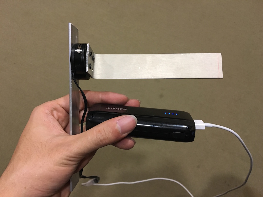
First I tried simply put the IMU on the base and provide negative feed back on the motors, like the video below. However, the iphone abviously shake and the final plan was to put the IMU on the same stage as the phone.
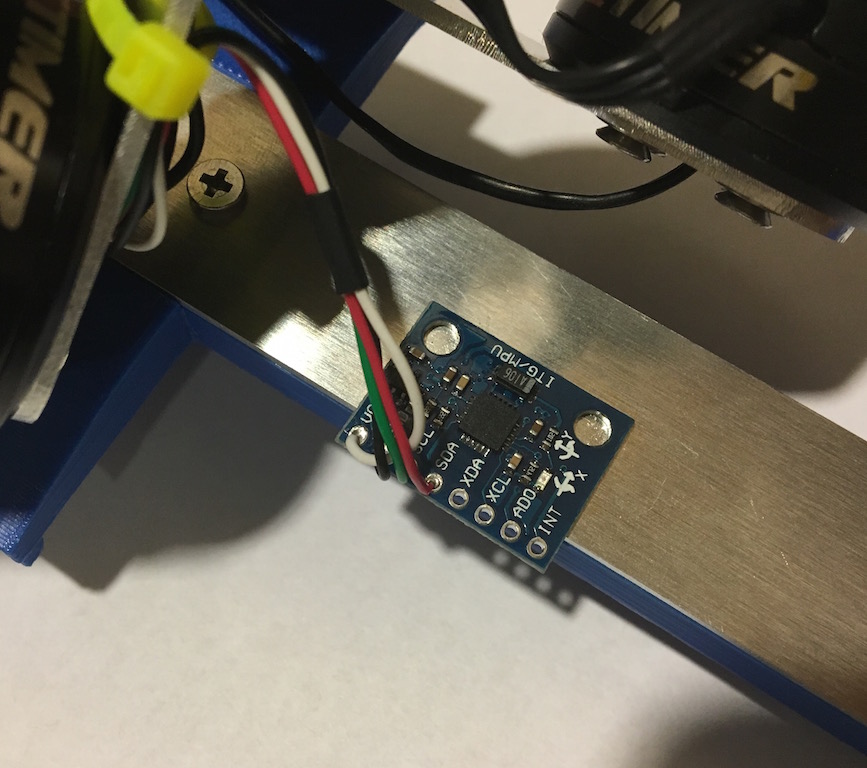
So later I put the IMU sensor together with the camera on the rotator. With the first trial, I set the sensor to read 50 times a second, so the IMU can have a more stable reading with longer integration time and I only use the gyroscope reading to start with. However, the stablizer self-oscilate like crazy when I add a large feed back (P>0.3). I tried different PID settings to stablize it but none of it works. I can only stablize it with P< 0.3 but that won't provide enough feedback to stablized the camera. So I started to think about why it self-oscilate. As a physicist, I wrote down the equation of motion for the rotator.
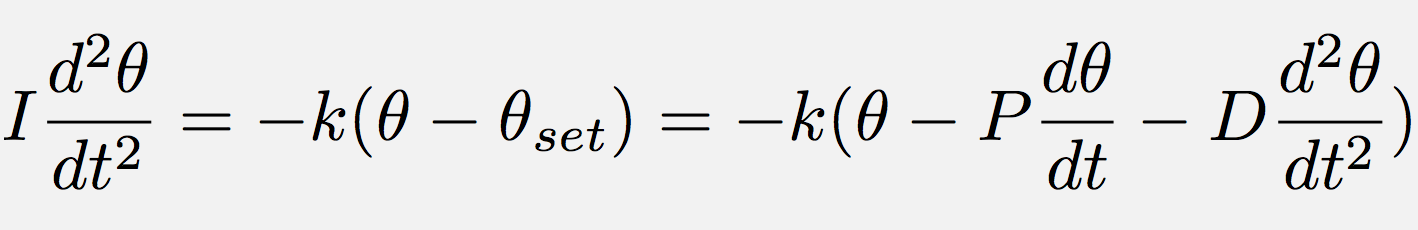
In the equation, the k is elastic constant of rotator around the stator of motor, and theta is the angle of the rotator, with P the propotional term of the sensor reading while D is the diffrential term. With the equation, I realize the P term should not cause the oscillation as it did. So I started to think it can only be due to the delay of sensor reading and the feed back. Then I tried to set the sensor delay time to minimum and read 1000 point per second, and I am happily seeing it stablized itself no matter what the PID setting I use. And with some tweak the PID setting (P=30, D=65), I got pretty fast response and smooth converging. The code for this program is here and the key part of the code is shown below.
...
void stepM1(int16_t *steps){
 if (*steps > 0){
	stepforwardM1();
	(*steps)--;
 }
 if (*steps < 0){
	stepbackwardM1();
	(*steps)++;
 }
}

int main(void) {

...

  while (1) {
    if (j >= sensormotor) {
       MPU_read(0x3F,&AcZ);
       MPU_read(0x43,&GyroX);
       feedAcZ[3] = feedAcZ[2];
       feedAcZ[2] = feedAcZ[1];

       feedGyroX[3] = feedGyroX[2];
       feedGyroX[2] = feedGyroX[1];

       feedAcZ[1] = AcZ*4.0/65536.0*1048.0*7.0/3.14/2;
       feedGyroX[1] = (GyroX+500)*500.0/65536.0*interval*sensormotor*1048.0*7.0/360.0;
       //seems sensitivity is 500deg*1.3 instead of 500deg
       if ((GyroX > 32760) | (GyroX <  -32760)) {
       setpoint = feedAcZ[1]*0.02+GyroX*500.0/65536.0*interval*sensormotor*1048.0*7.0/360.0*30;}
       else {
       setpoint = -feedAcZ[1]*0.1+feedGyroX[1]*30+(feedGyroX[1]-feedGyroX[2])*70;}
       steps = (int) setpoint;
       if (steps >= sensormotor) speed=1;
       else speed = sensormotor/abs(steps);
       printf("%" PRId16 "\n",GyroX);
       j=0;
    }
    else{
    j++;
    }
    if (j % speed == 0) stepM1(&steps);
    _delay_us(interval);
  }
}
Because I need to control three motors which requires nine timer/counter, so I used two ATmega328p and serial communication between them. Detail is in the communication week.
I made the frame using Shopbot desktop. And bend them to shape in a metal bender.
Then I put everything together. As shown following:
I haven't tune the PID to optimum, but this following video demostrate it already works to the first order.