Week 5 - Electronics Design
OVERVIEW
This is the second week in electronics. Our goals this week were to design a PCB so that it includes a few peripheral or interactive components (eg. a button or an LED). Of course, we also mill and solder the components to the board.
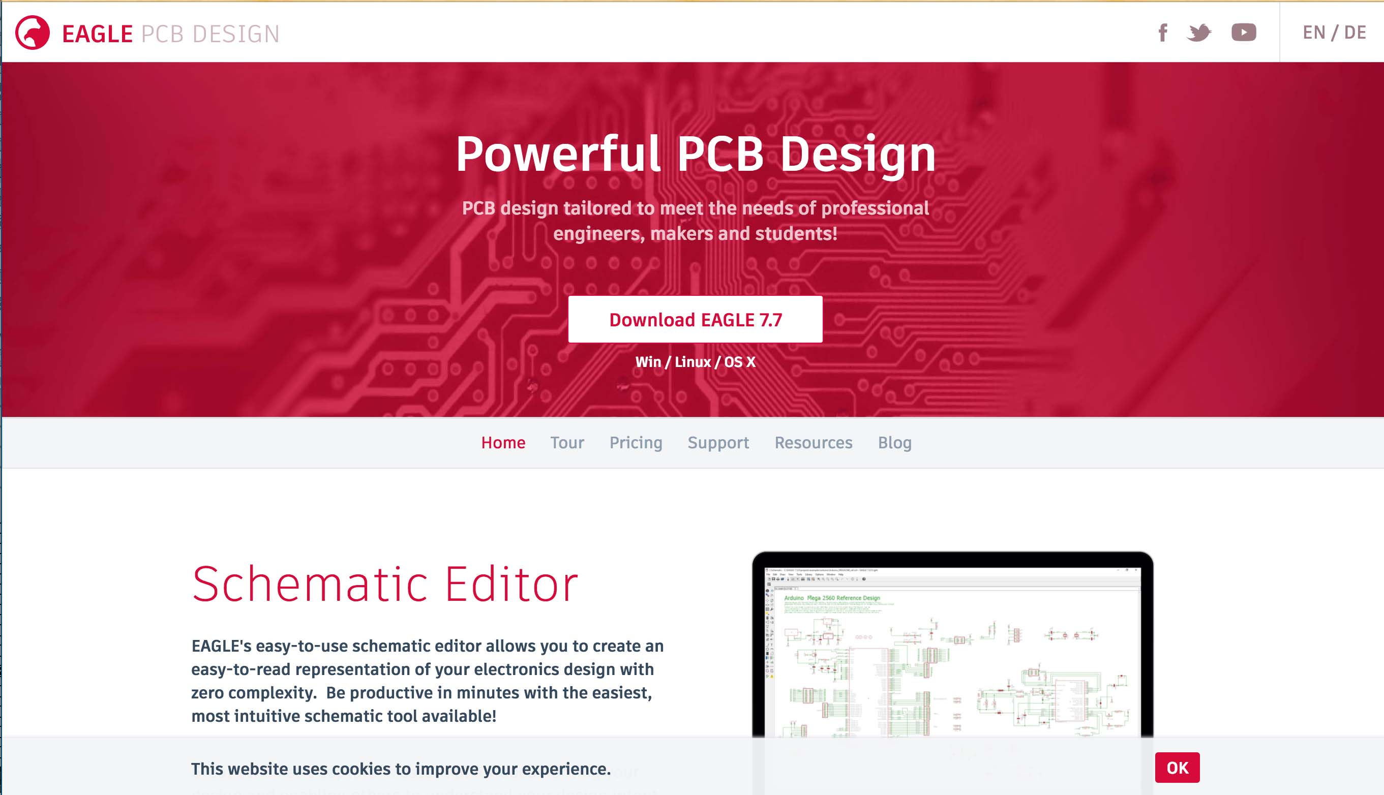
I selected EAGLE as my software package to design the board since it has a large community, is free, and it will be integrated into Autodesk products soon. Additionally, my electrical engineer friends suggested it. All around, it’s a pretty safe bet for a noob.
Learning the skill
- Eagle — $FREE
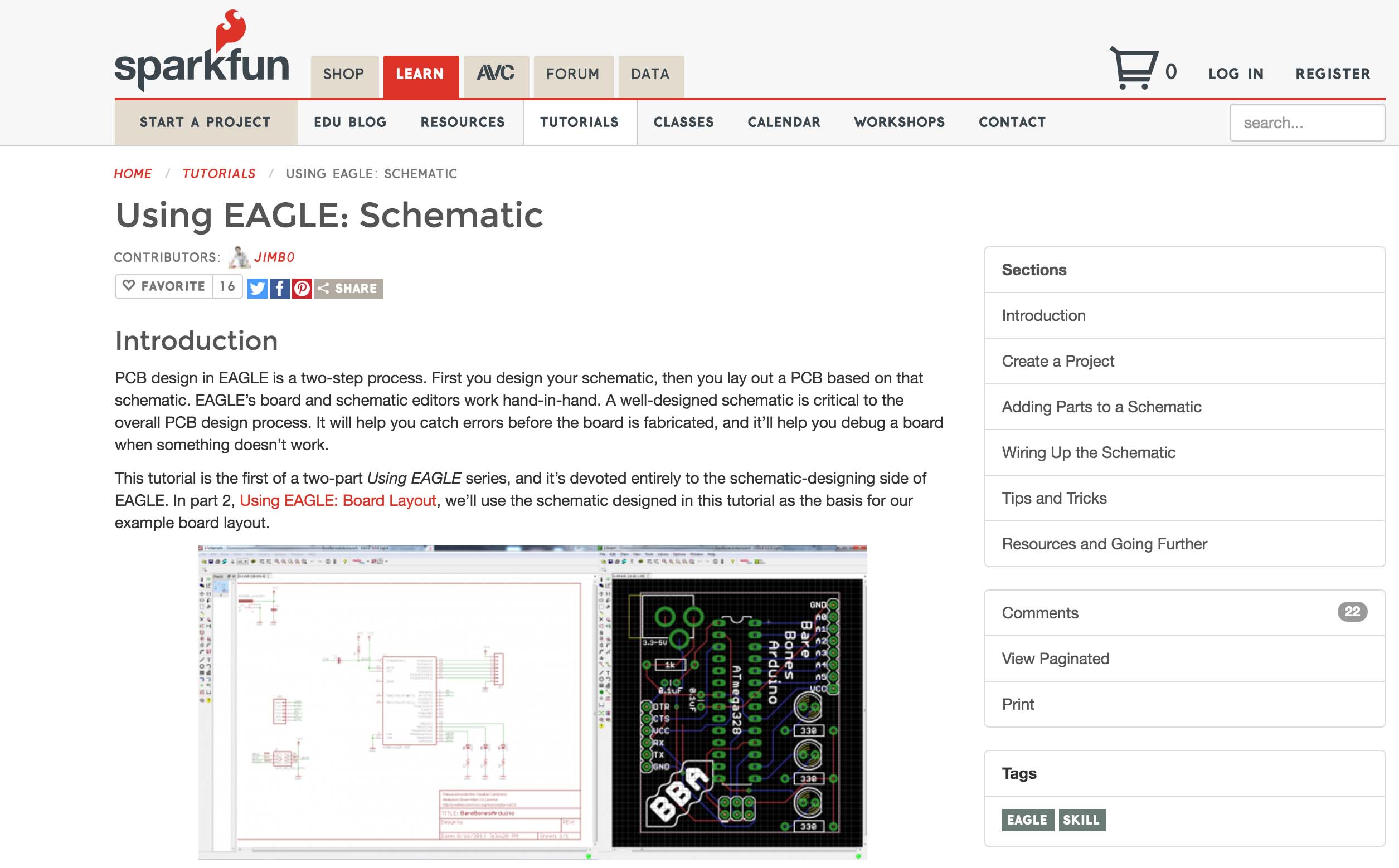
Getting up and running with Eagle is a breeze. I found some helpful tutorials at SparkFun. Going over electronics basics was helpful as well. Here are a few good ones from SparkFun:
Electronics Fundamentals
Setting up EAGLE
Using EAGLE Schematic
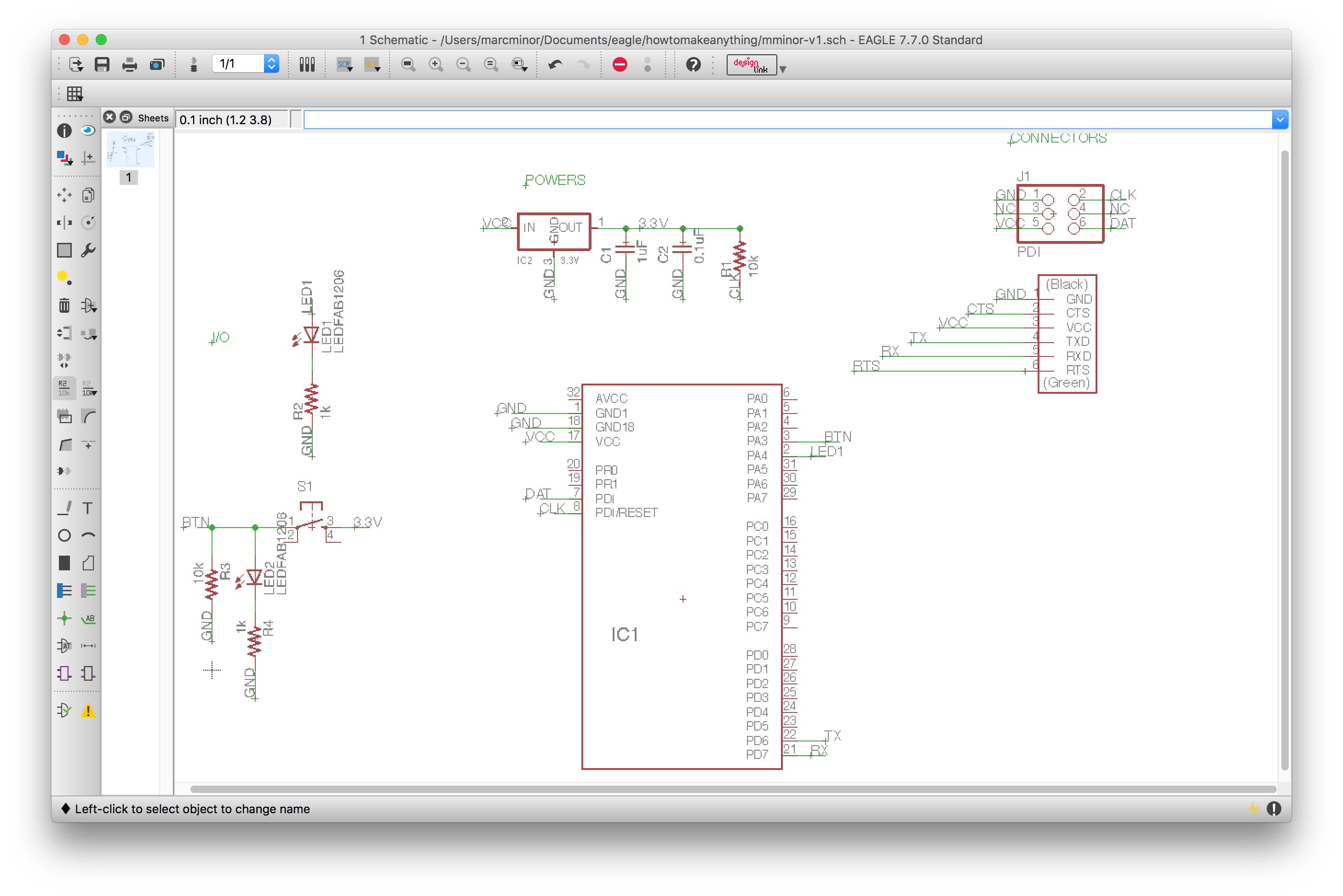
The key thing to remember when designing in EAGLE is that a well designed schematic will save a ton of time placing the components and routing the traces. Spend the time getting the schematic right before jumping over to the board view. The board view and schematic view are connected, so definitely don’t close the schematic when you work on the board. The tools are surprising intuitive in EAGLE and the handy command line shortcuts speed up the process significantly.
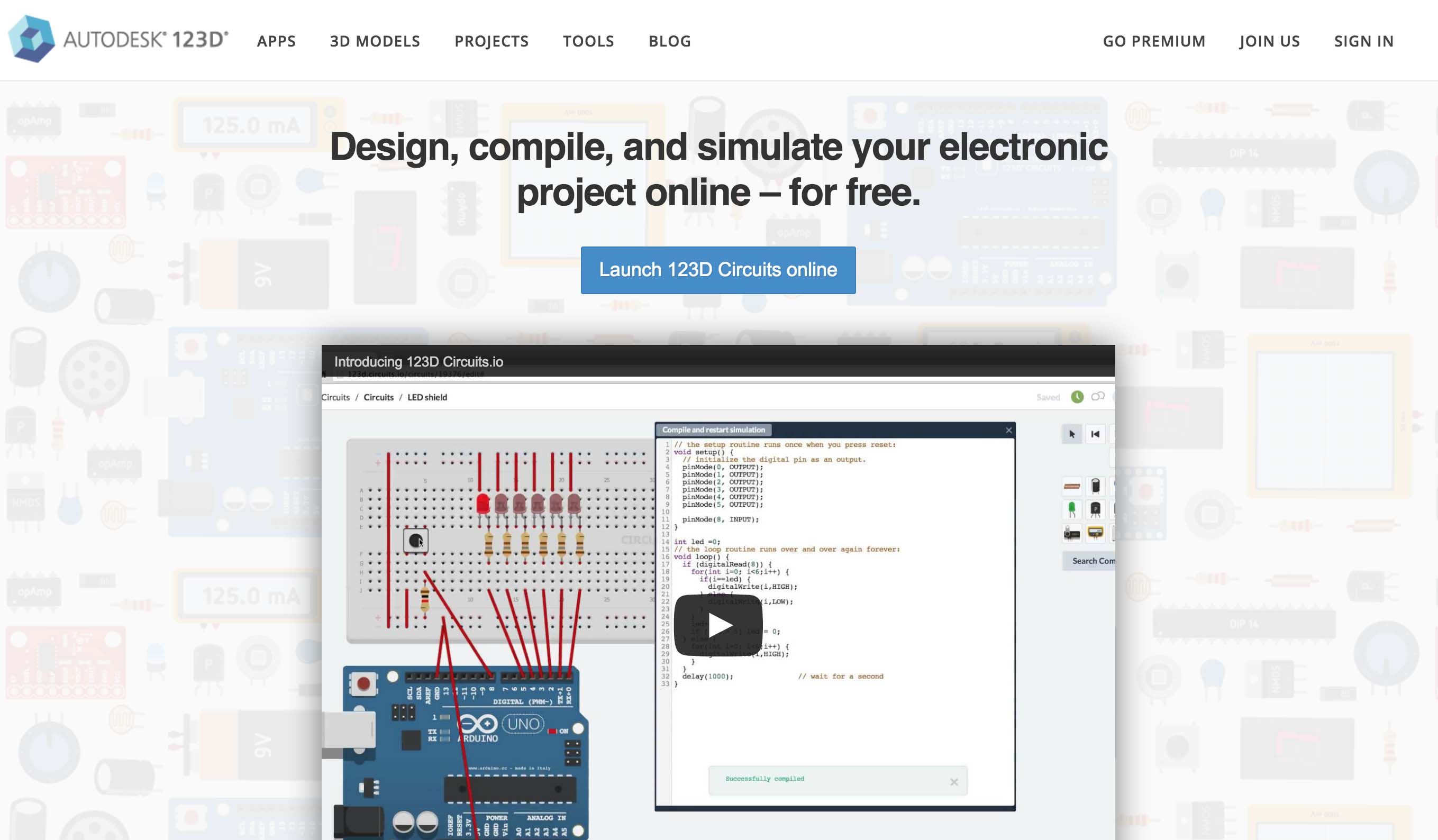
I attempted to simulate my board design using 123D Circuits but found it a bit difficult to get around the breadboard-centric, ‘create your own here’ set up and quickly gave up. I was excited to make the thing anyway.
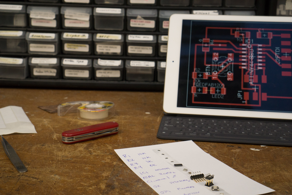
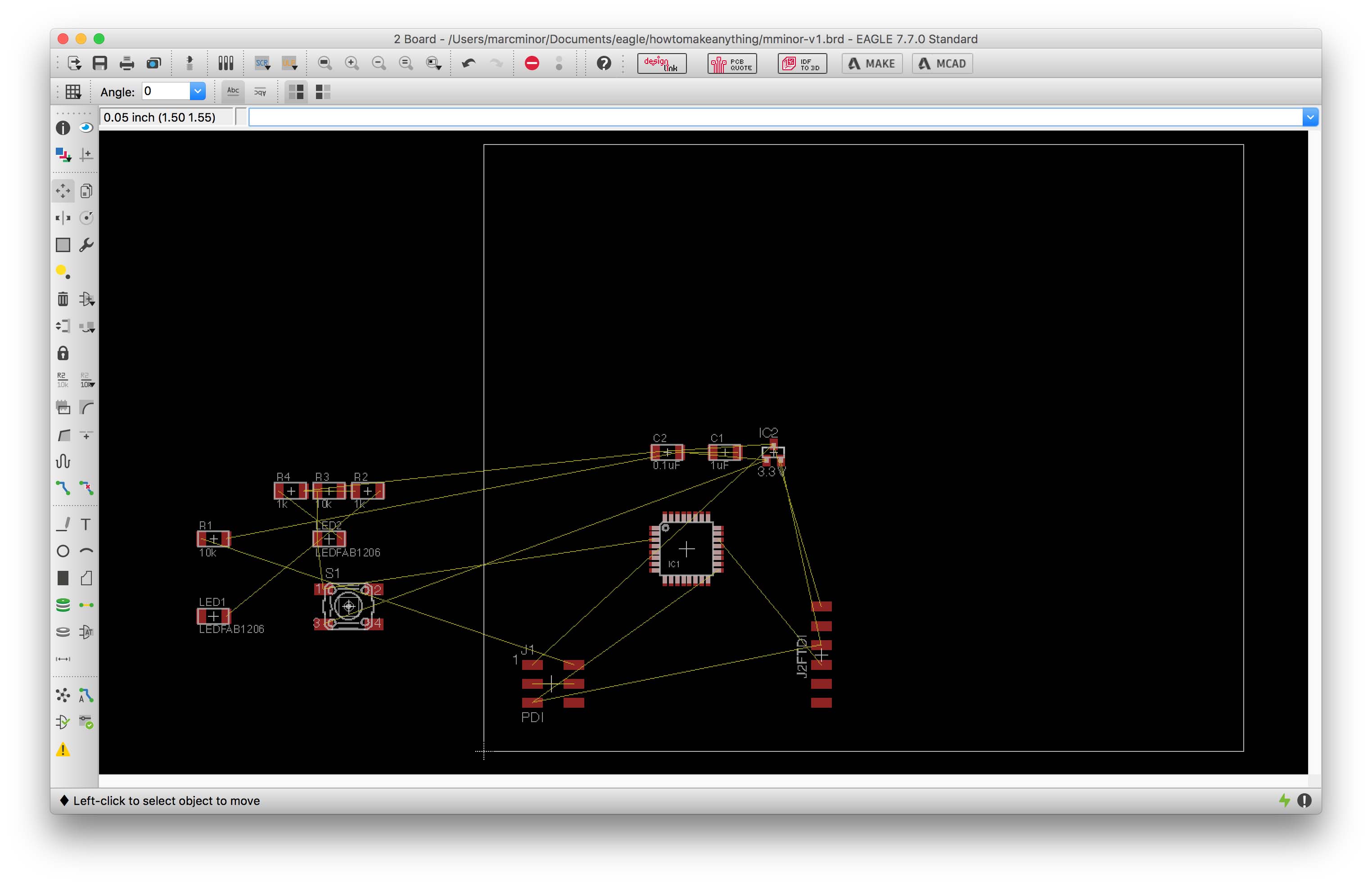
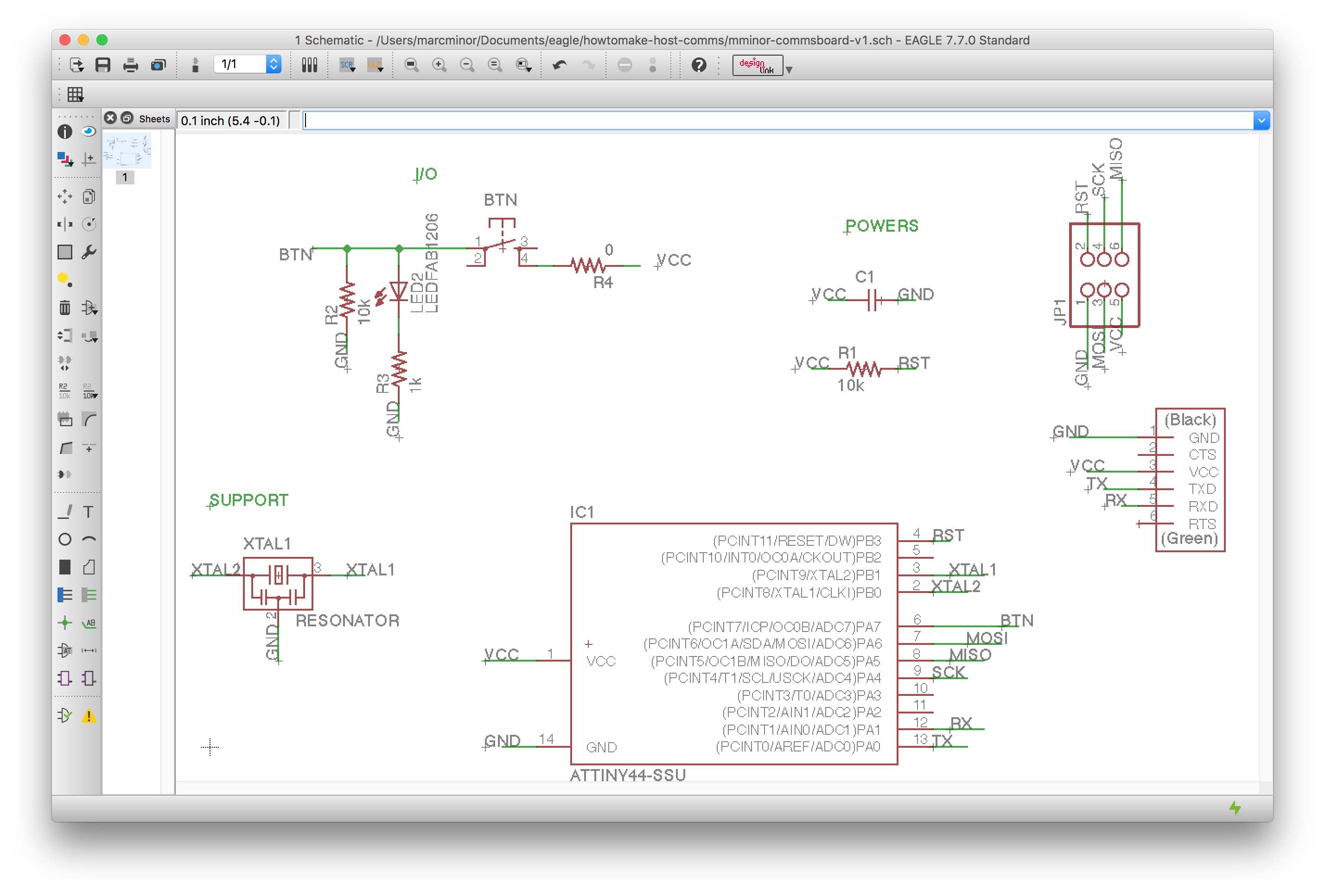
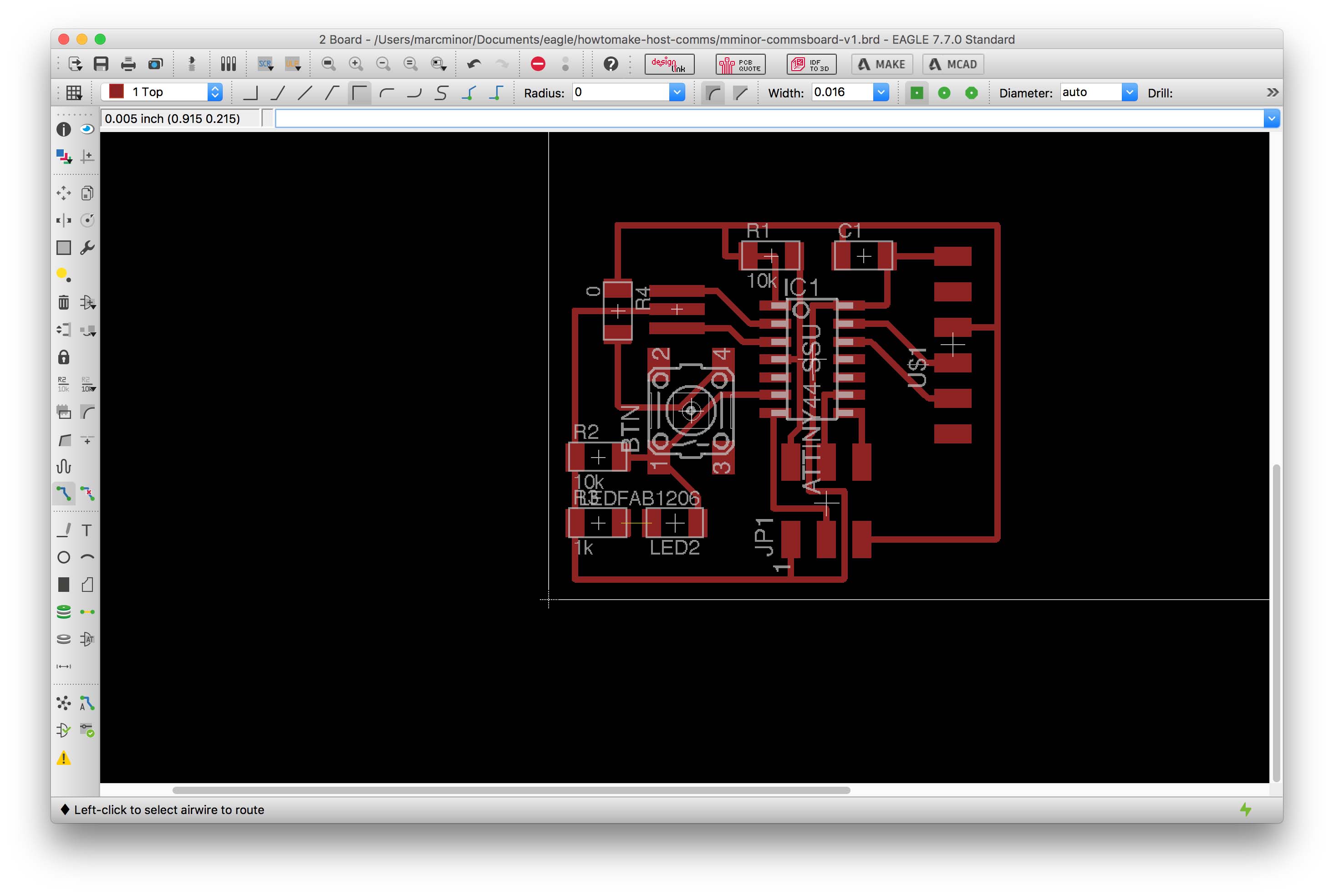
Schematic & Board design
Struggling with selecting the libraries, components, and instructions is a great way to quickly get up to speed on circuit design. I found myself learning a bunch about each component as I struggled and didn’t realize how much progress was being made (somehow I expected circuit design to be esoteric and math-like in its approachability). Once you get into a flow with the commands it can go quite quick. Unfortunately, I spent my learning curve designing the incorrect board XMega. I had to start over and design the correct communications board.
Here are some takeaways that should make the process go much quicker for other noobs:
- Download the fablbr from the website so you have the correct components in your design software.
- Make sure you’re looking at the correct board. Double check.
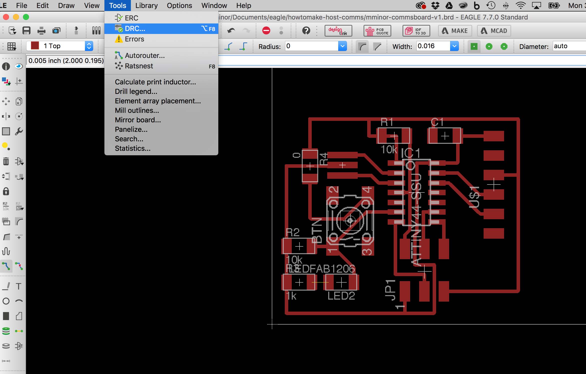
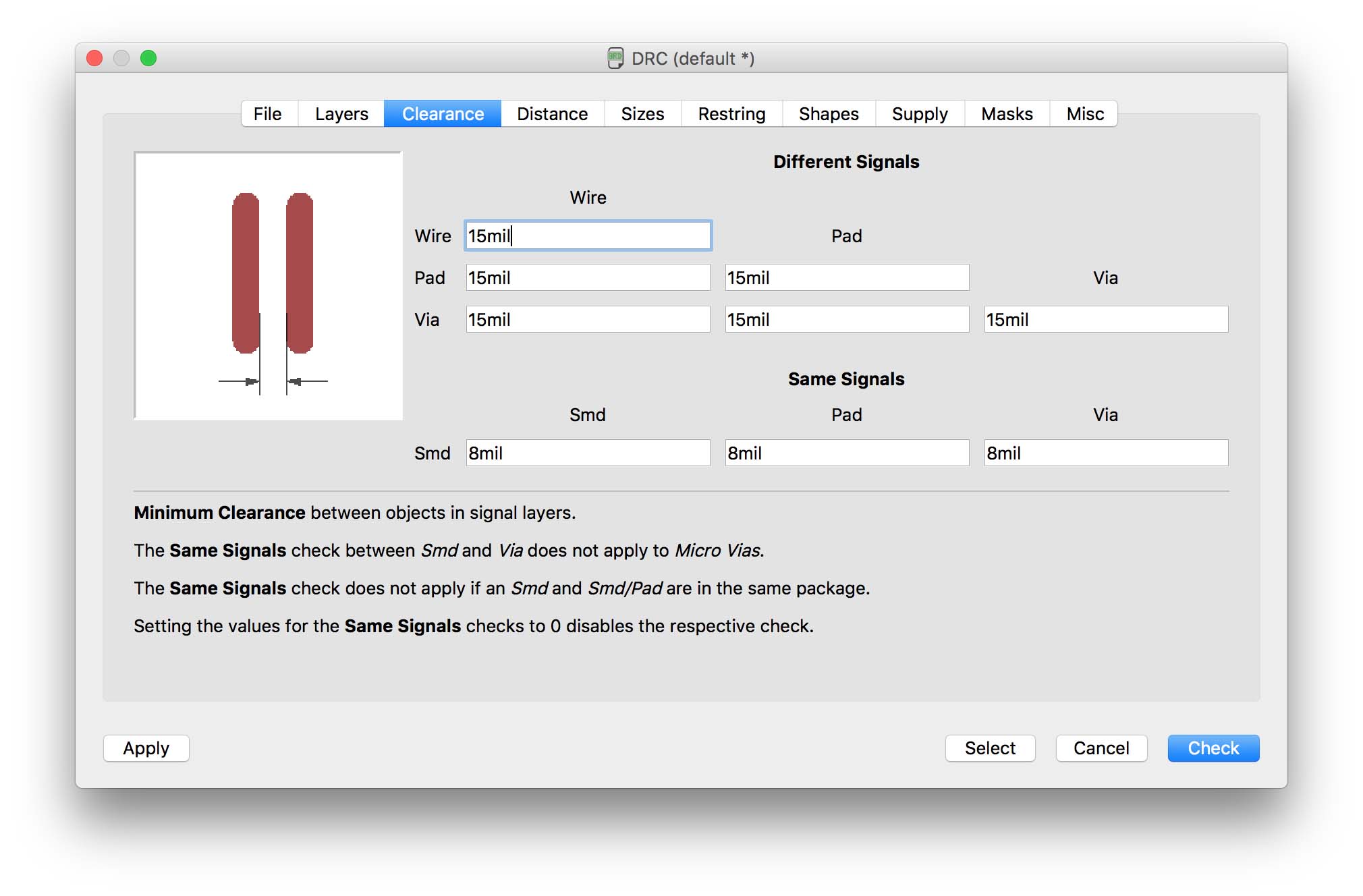
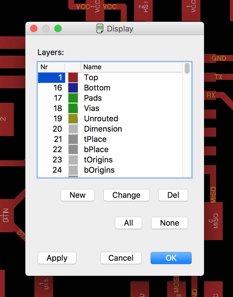
- Check your design rules (this is really simple, honestly…just remember to do it)
- Brush up or get solid on V=IR and understand what each component is doing.
- Make an account with element14 if you want easy to access components.
Round 1 - XMEGA by accident
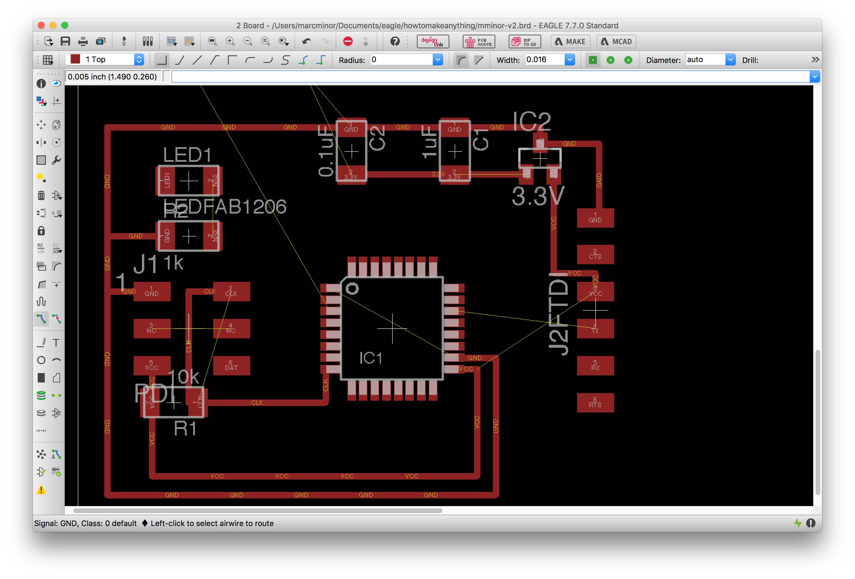
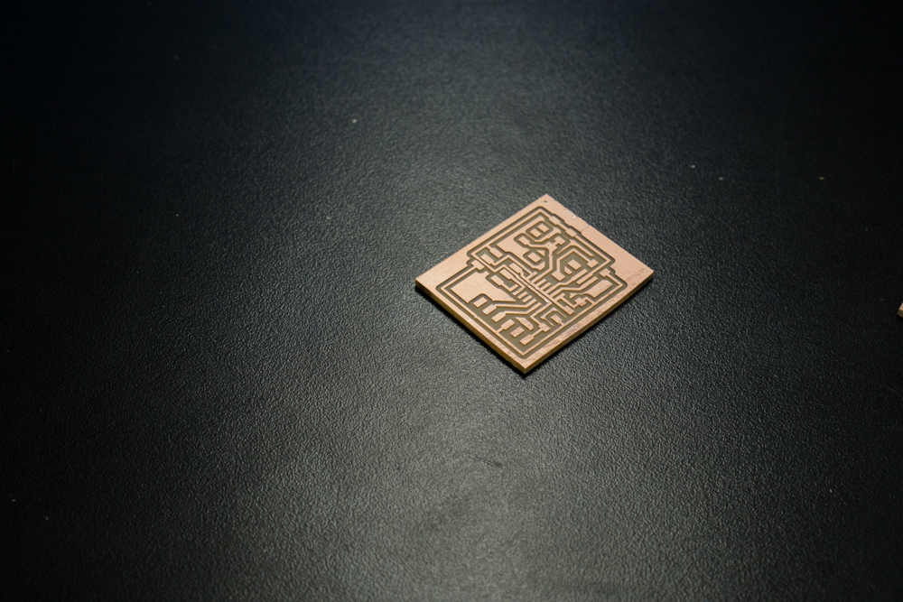
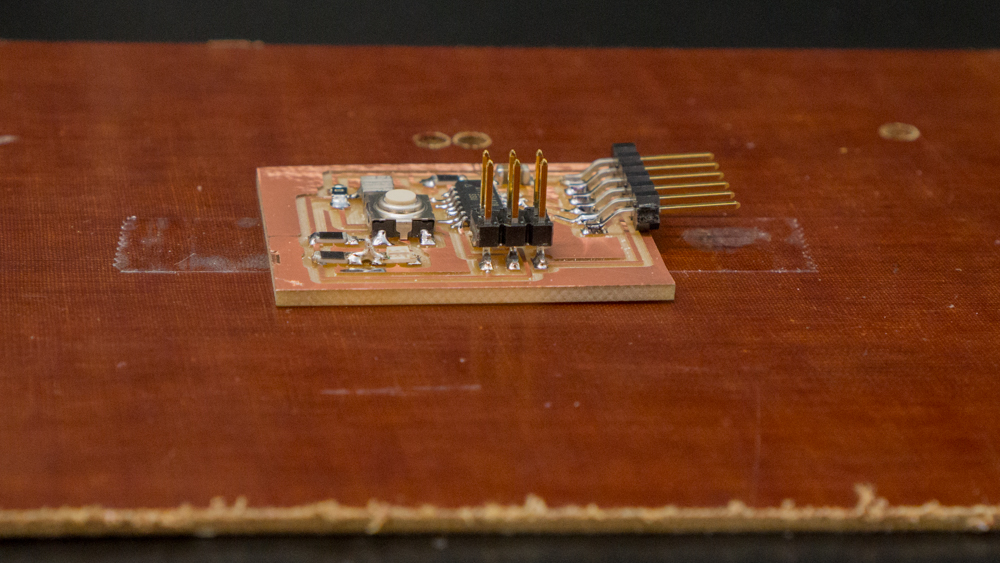
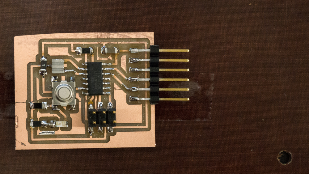
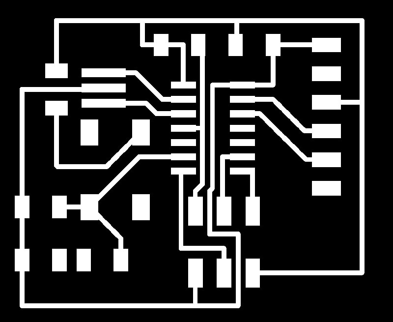
Round 2 - Communications Board
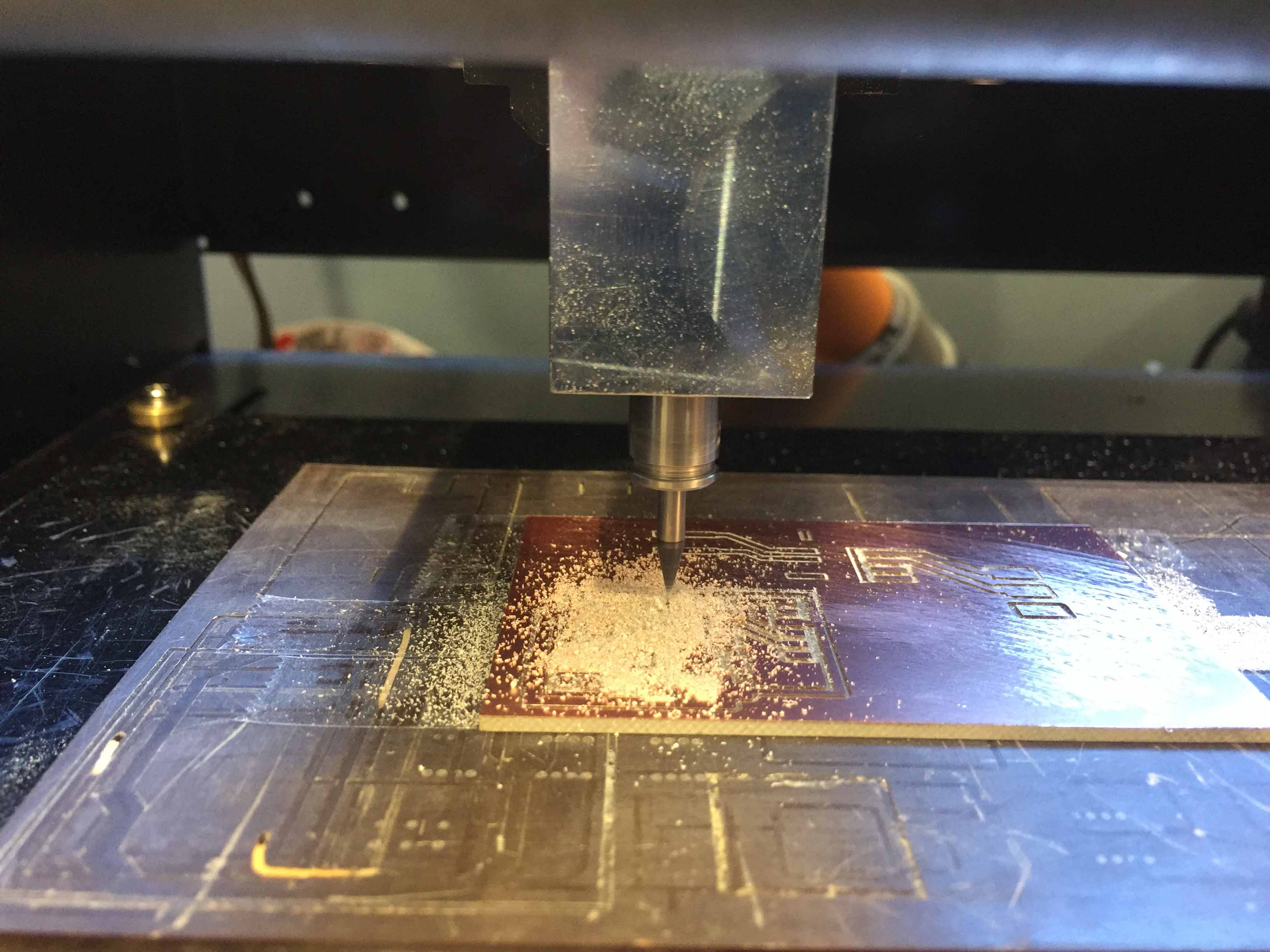
Milling & Soldering
The actual process of milling and soldering was a breeze. I encountered friction with the following:
- Finding the right tools
- Trouble shooting getting the roland mill to start
- Learning how to operate the shopbot
- Fixing design mistakes in production…
There is so much to say for having the right tools at hand. That is one of the great strengths of the fablab approach. Sometimes, something will be missing though and that just stinks for productivity. I searched for a fair bit to track down the allen key to adjust the roland mill before I could finally get going. Once I did adjust it, I was stuck with a connection issue between the computer and the mill. Loading the mod_settings wasn’t working and I just couldn’t get the roland mill to work. I started using the shopbot but eventually decided to go back to the roland mill since I was concerned I hadn’t been trained on the shopbot. Restarting the computer ended up fixing the problem lol.
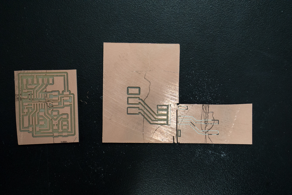
The more important challenge were the design issues I ran into during production. Its hard to avoid, I suppose, but sometimes you don’t find out about design mistakes until you are in production. I had two major design issues that I dealt with in production:
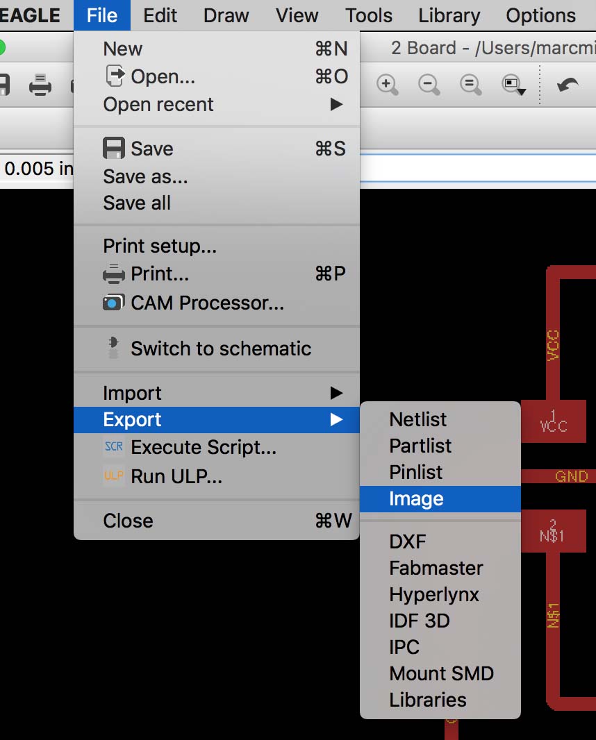
- My design was scaled by a factor of 2 thanks to the retina display (apparently). As you’ll see below with the false start, I ended up having to find that out during milling.
- There was a very small trace missing from the design connecting a series resistor to an LED. I only noticed this when I was soldering and had to create a solder bridge to address it.