Final Project
OVERVIEW The goal with the final project is to synthesize a range of skills in order to rapidly test and iterate on an idea. That means the project needs to reflect challenges in 3D modeling, fabrication, embedded systems programming, and interactivity.
My concept for a final project is a connected trail light for public spaces. This product is rooted in the idea of intervention - strategically altering a context and experience to influence behavioral change. My hope is to improve communities by encouraging positive shifts in individual behavioral patterns. Healthier people build healthier communities.
This product would play two roles in the context of a public running trail.
- It provides light when it is dark. Running trails can be dangerous in the early morning and at night due to the lack of artificial or natural light. Well-lit public spaces
- It works with a collection of trail lights to create interactivity in the environment (the light reacts to users) and logs a user’s activity. It would not only change its display as a user passes but it would also log their progress if they signed in.
REQUIREMENTS
- Low-cost (feasible for parks & recs departments to implement)
- Self-sufficient energy source (solar)
- Internet-connected
- Simple to ship & install by low-skill labor
- Resilient to weather and human fouling
- Requires little interaction / hardware from users
- Beautiful and joyful to pass
Concept
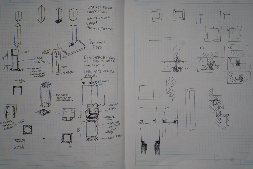
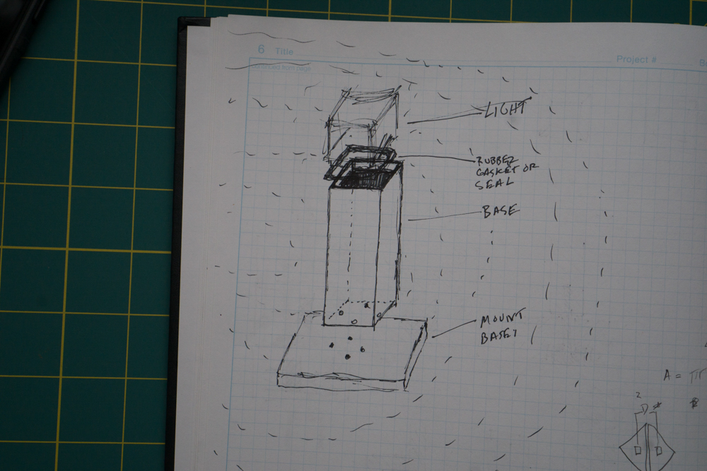
The form and function of the light was somewhat obvious, due to the requirements that this be low-cost and easy to install. I did a bit of sketching to work out some basic details about what I wanted to model and quickly moved into testing out software.
I considered a variety of approaches for logging a user’s run in a public context (as opposed to using a FitBit or personal device to log activity). I settled on the light because of its aesthetic qualities and base functionality — every community understands the value of well-lit spaces. Additionally, the electronics and programming for such a product are well documented (read: this is achieavable for me).
I wanted to investigate how I might accomplish the different states the trail light might have. I considered how I might embed LEDs directly into the enclosure, automatically generating a randomized, pattern of parametric holes that would perfectly fit the LEDs. This proved to be a bit too much to dig into at this point.
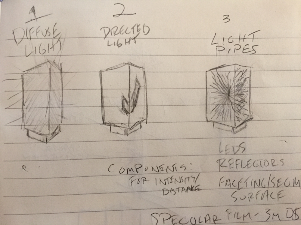
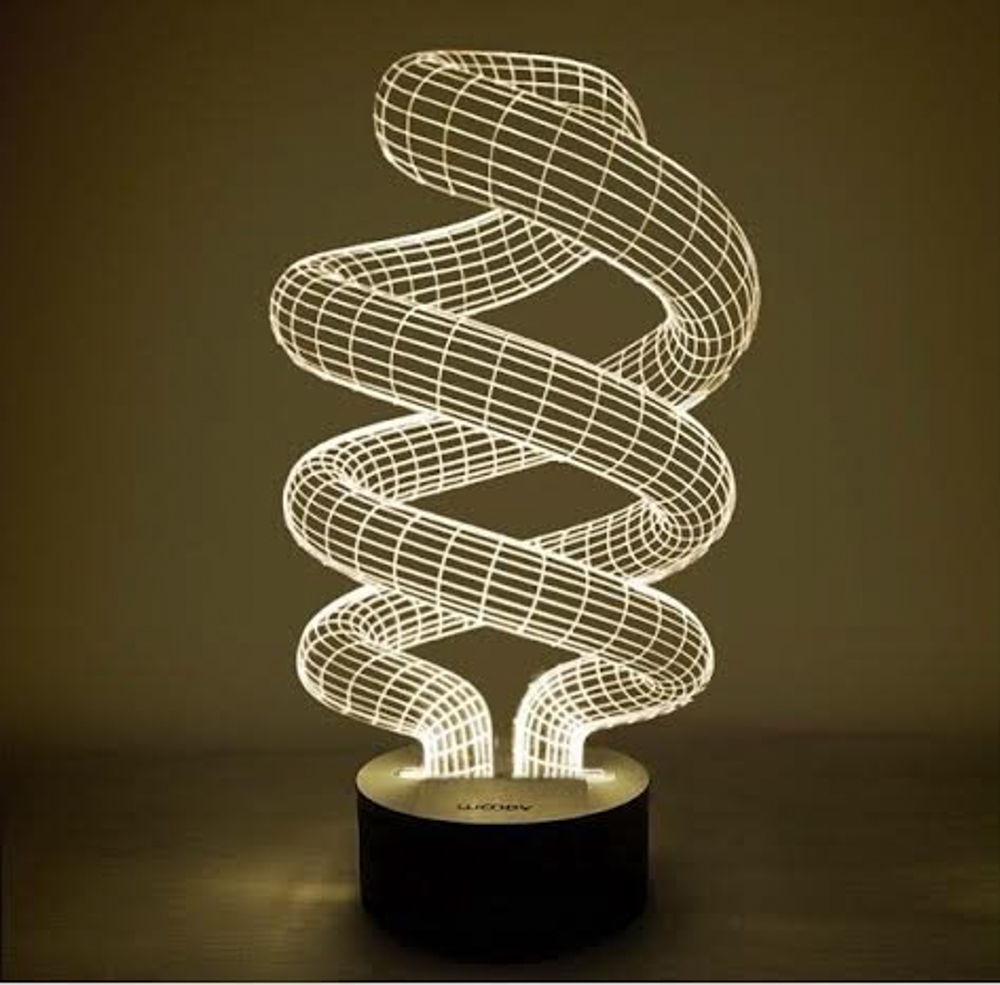
 I decided to simplify my intentions for this week and potentially for the way to execute the light overall. I was inspired by the Bulbing Table Lamp of MOMA store fame. I wanted to build a basic double helix structure for inside the lighting enclosure that would have diffused fiber optic cables embedded in it.
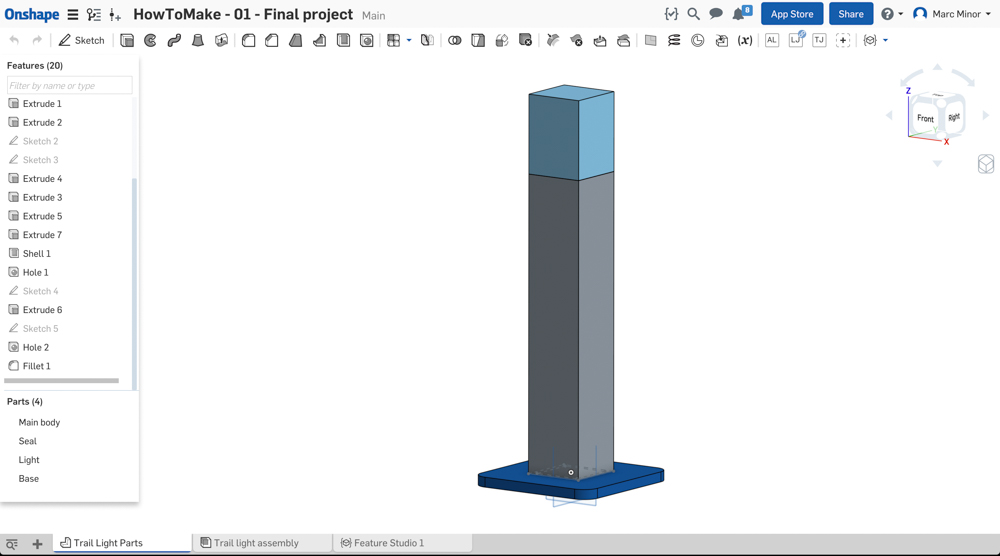
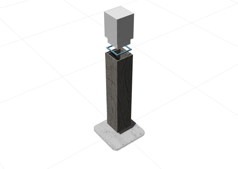
Modeling
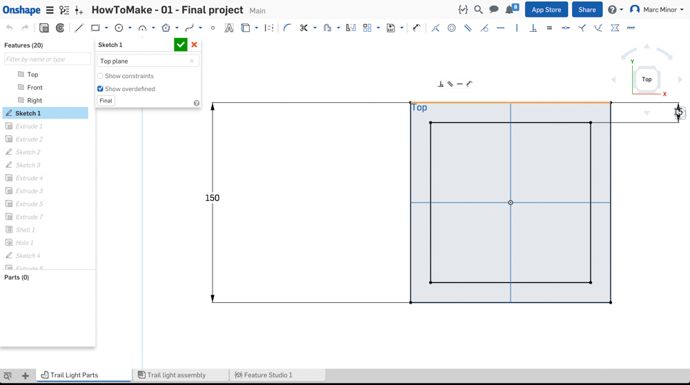
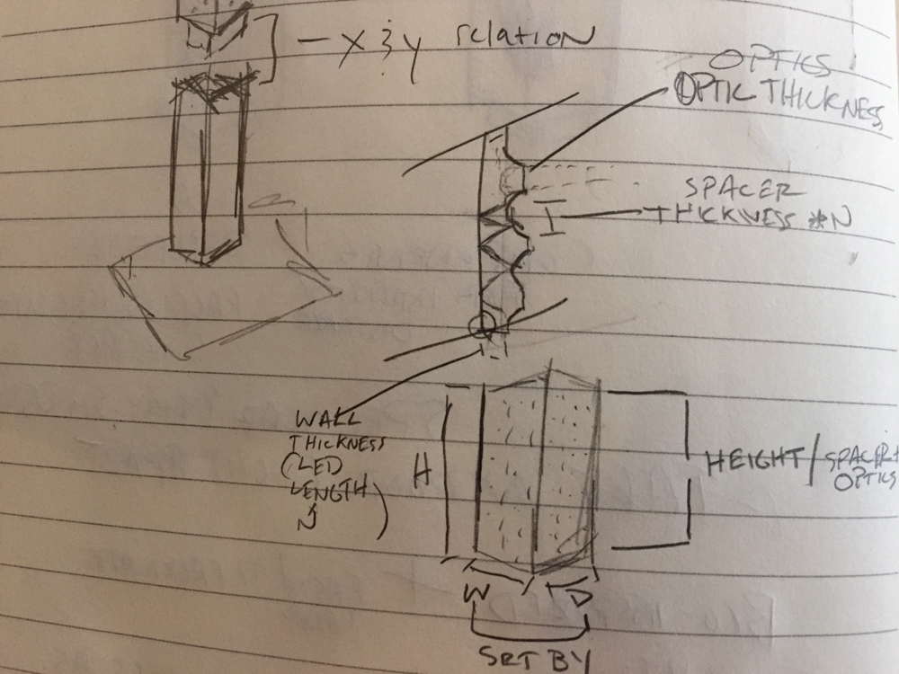
I relied on basic shapes. My design intent was to that the proportions should remain the same but size of the assembly should be able to be experimented with either through changes to the base dimensions or the height of the light enclosure (for example). The resulting model was constrained somewhat quickly with just enough dimensions declared to make a parametric model based on my simple goals.
I experimented with textures and rendering in both OnShape and in Rhino. At the end of the day, I preferred Rhino for rendering. This was more a fact of my limited experience though. I did try a composite image with the light in a photo but it turned out bad…to say the least…


Alternate Project Idea - Connected Pull-up Bar
I am considering a connected pull-up bar (ideally outdoor). Outdoor pull-up bars are increasingly common but they are often badly designed. Additionally, they represent an excellent opportunity to bring an element of playfulness and competition into what is often banal. This pull-up bar would use FSRs combined with a break beam sensor to determine if the user is starting, completing, or failing a pull-up attempt.

Fabrication
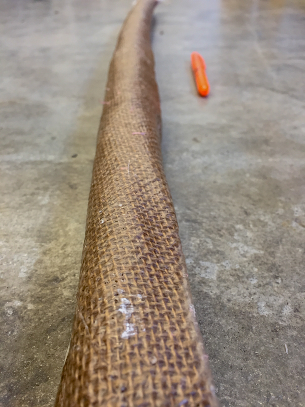
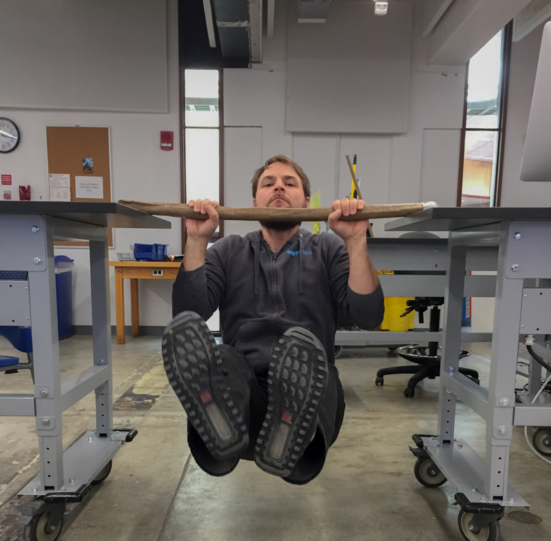
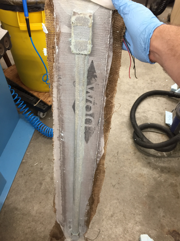
This exercise ended up being a successful demonstration of the strength and simplicity of creating a composite pull-up bar. As I suspected, though, the lack of a mold to restrict folding, pinching, and deformations during the cure is a major problem. Not only are there significant pinches throughout the bar, but the overall shape also deformed (it appears as though is is bent) from the cure. Additionally, the mold release and polyester batting folded into the structure near one end, requiring the use of a saw to remove it.
My next steps are to create a new version of the bar with force sensitive resistors embedded in it just below the final layer.
Force Sensitive Resistors
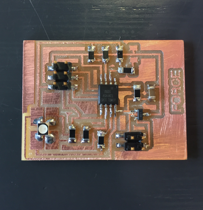
My next step is to add a 10k resistor to the wheatstone bridge so that it is balanced and to include an RGB led for an output. I designed and stuffed the board as part of this week, though I haven’t had the chance to program it yet.
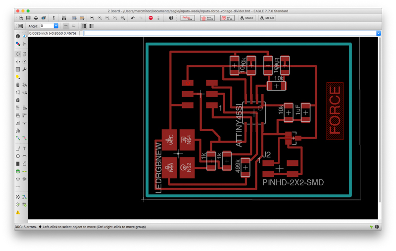
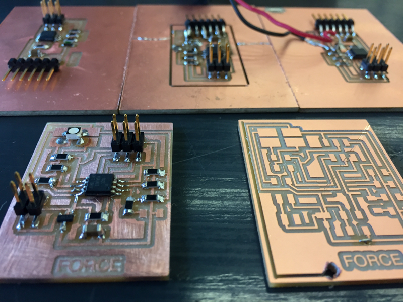
Both boards were milled on the shopbot with the new fab modules (which work great, for the most part). The speed was somehow off for the first board though and the shopbot jerked around as it sped across the toolpaths. The result was a very iffy board in need of serious sanding. While it is a mess, it does work…
Effectiveness & Placement of Velostat
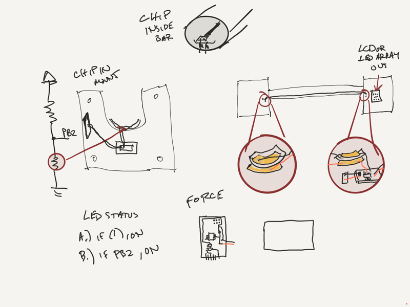
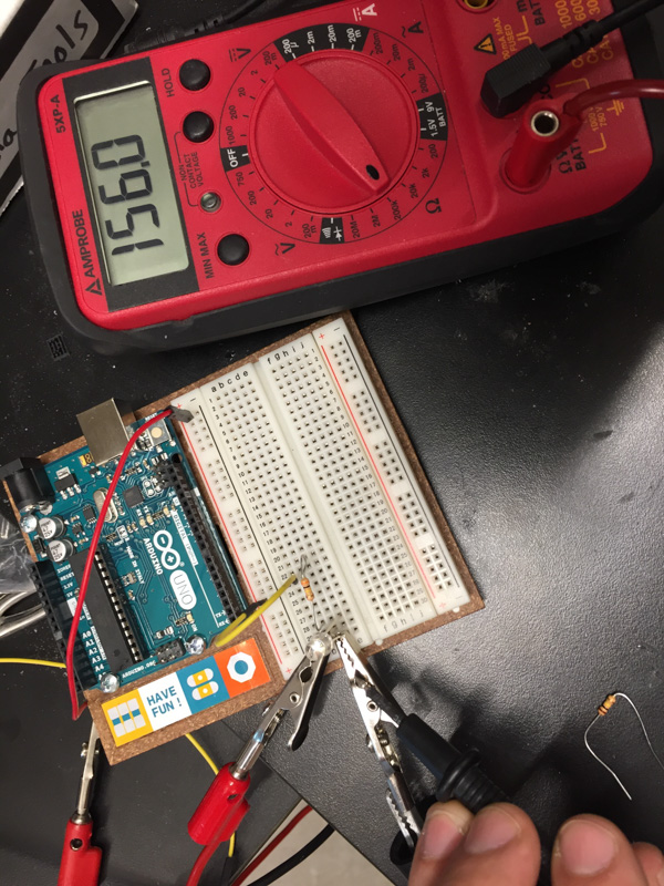
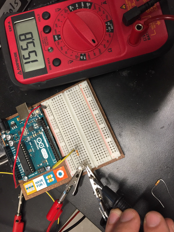
I thought a bit further on the implementation and overall arrangement of the force sensors with the output device. The resistivity of Velostat increases linearly with the length and width of the material, so wrapping the bar in the material along with wires isn’t going to work. I did several tests with a multimeter to work this out. The plan will instead be to create mounting blocks for the bar which will incorporate the velostat on either end. The force sensing board will connect to the display board through the mount.
LED Display Round 1
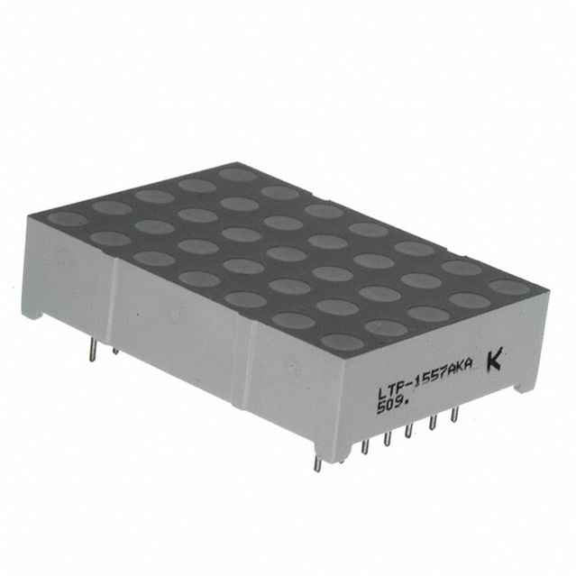
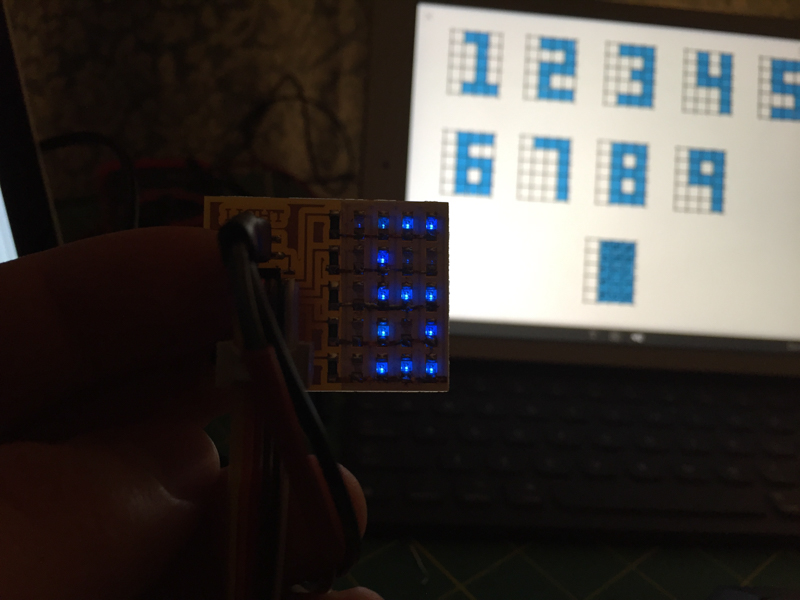
It was somewhat difficult to determine what output device to use for my first prototype. While I knew I wanted to display a count of successful pull-ups for my final project, I wasn’t sure which route to take for output device. I found a great looking 5x7 LED array in the lab with zero documentation or labels. Since it isn’t part of the FabLab inventory, I dug up the data sheet and worked on making sense of it myself.
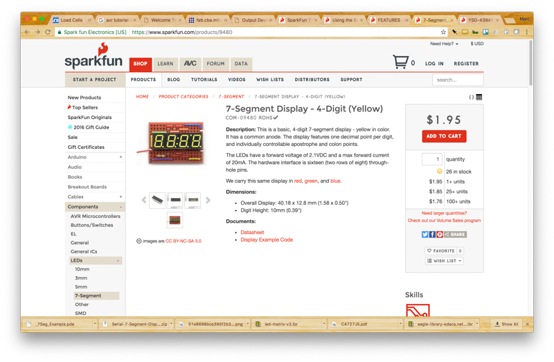
I was also considering a 4 digit 7-segment display component that was also in the lab but not part of the inventory. I found this AVR tutorial and this SparkFun walkthrough instructive on the basics.
I finally settled on just using Neil’s LED array in order to limit the risk involved (trying to learn just a few new things at once).
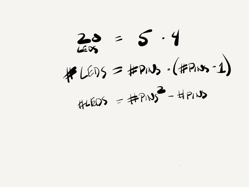
Charlieplexing can take a bit of acclimating to have it ‘click’ but once it does the rest of pretty straight forward. There is a neat little formula, for example, to determine the total number of a LEDs that can be supported based on the number of pins desired.
My goal for altering Neil’s script was to create the basis for a counter. This is really a prototype for the pull-up count display. I’ll replace the code and hardware with a more significant version in the final project. This is where the rubber meets the road and where really understanding how to target each LED matters.
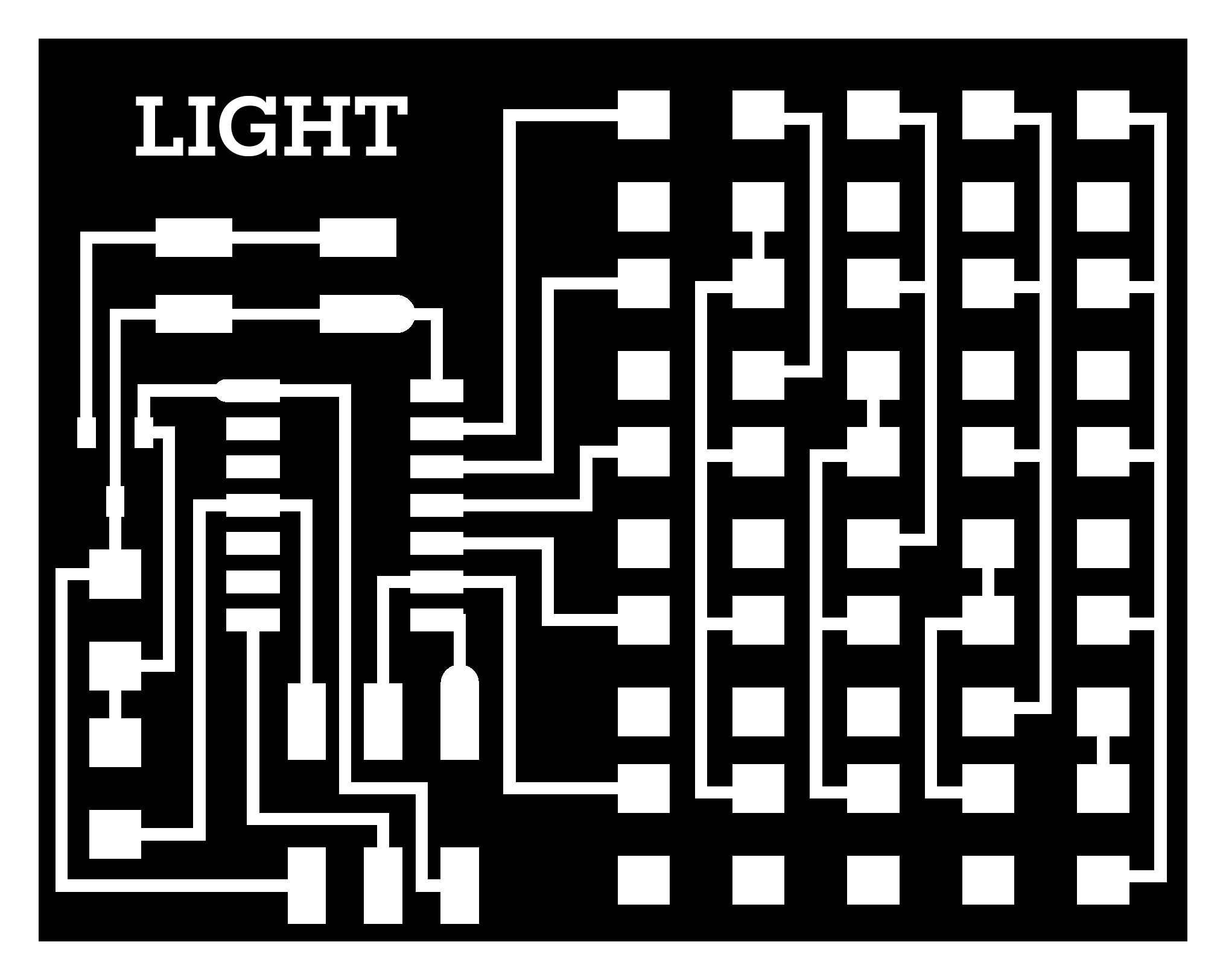
I drew a little schematic to help.
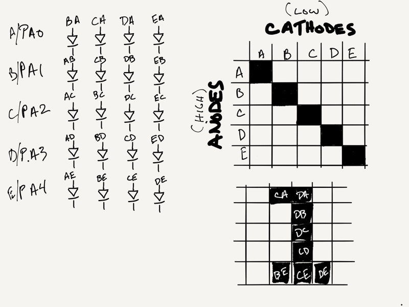
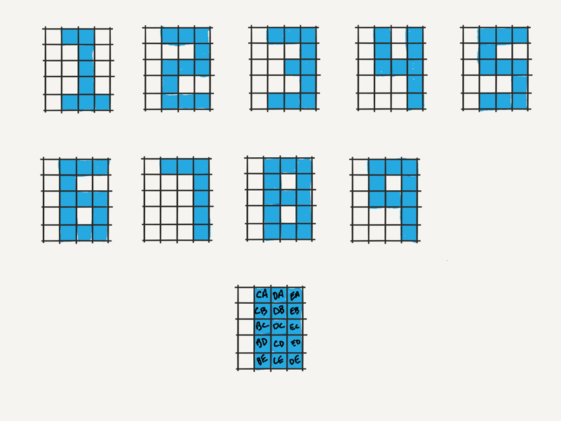
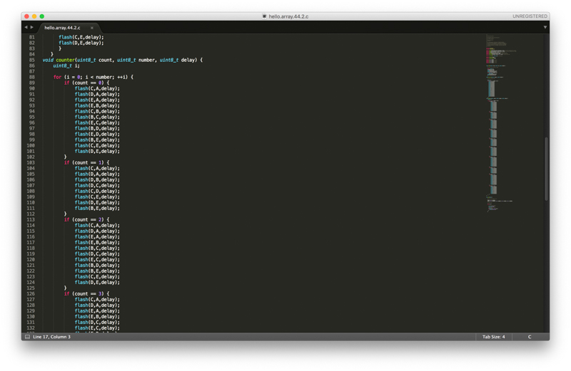
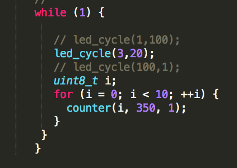
I created a bit of a brute force function for displaying digits called Counter using Neil’s flash function. I’m sure this will get refactored but it works for now.
We have NUMBERS! …
Some updates I’d like to make to this code for the final project will be:
- Counter has a session which is activated by force and time
- Counter listens for initial force change (someone is on the bar) and starts a session or ‘count’ based on that
- Counter receives count updates from force board and displays appropriate number for the existing session
- Counter has a time-out function to end a session
PROGRESS & RESULTS
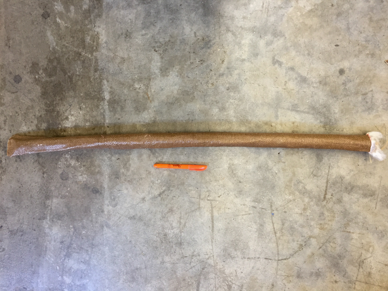
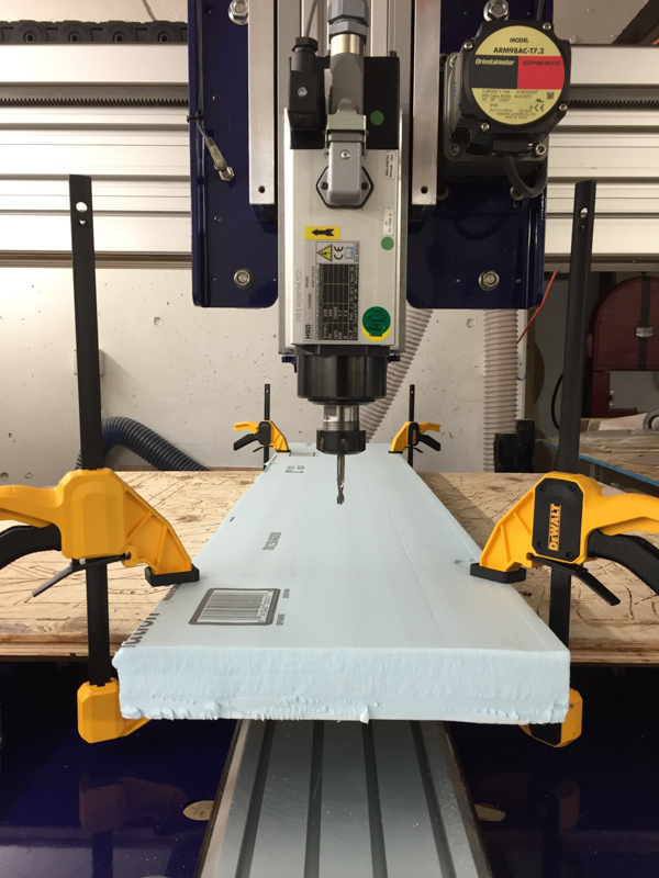
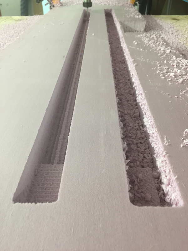
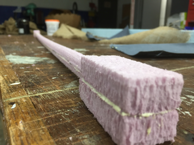
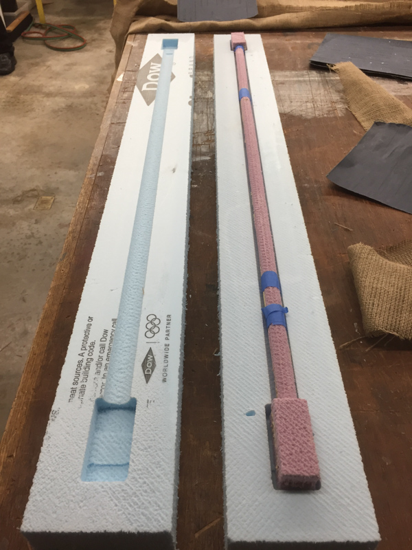
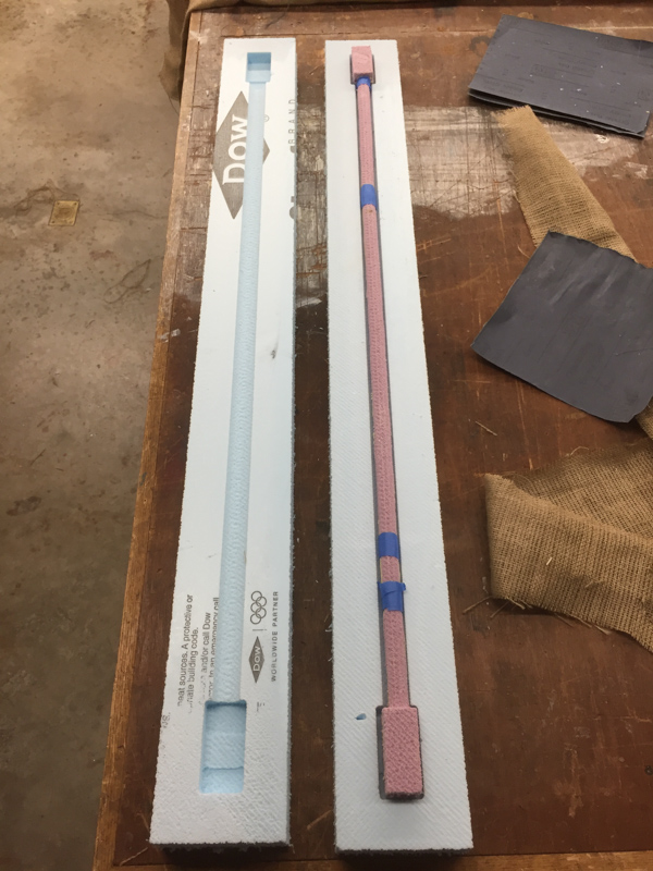
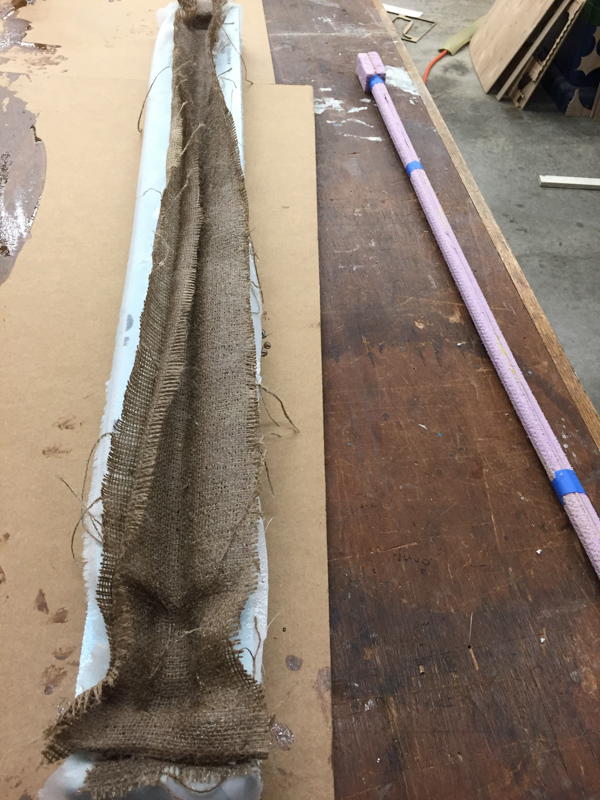
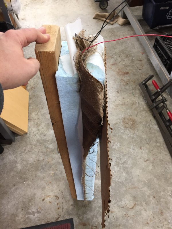
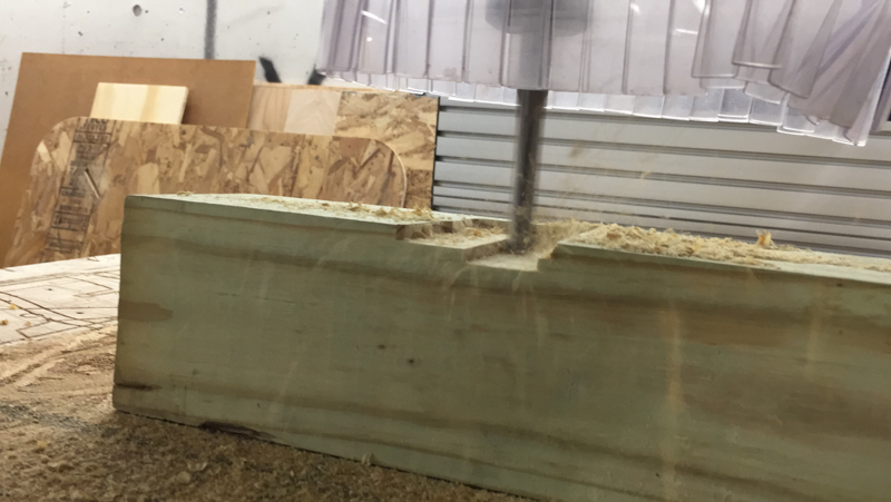
My first priority when it was finally time to spend a few days dedicated to the final project was to create a better version of the composite pull-up bar which would incorporate necessary wiring to connect the load sensors (VCC, GND, SIGNAL). This entailed milling out two negatives for the mold and a positive for the core. Since the pole was around 42 inches, this took awhile to get right. I used a 1/4” bit for the roughing, finishing, and cut out steps. I was happy with the quality at the end, even though it was a bit rough, since the burlap wouldn’t conform to fine detail anyway.

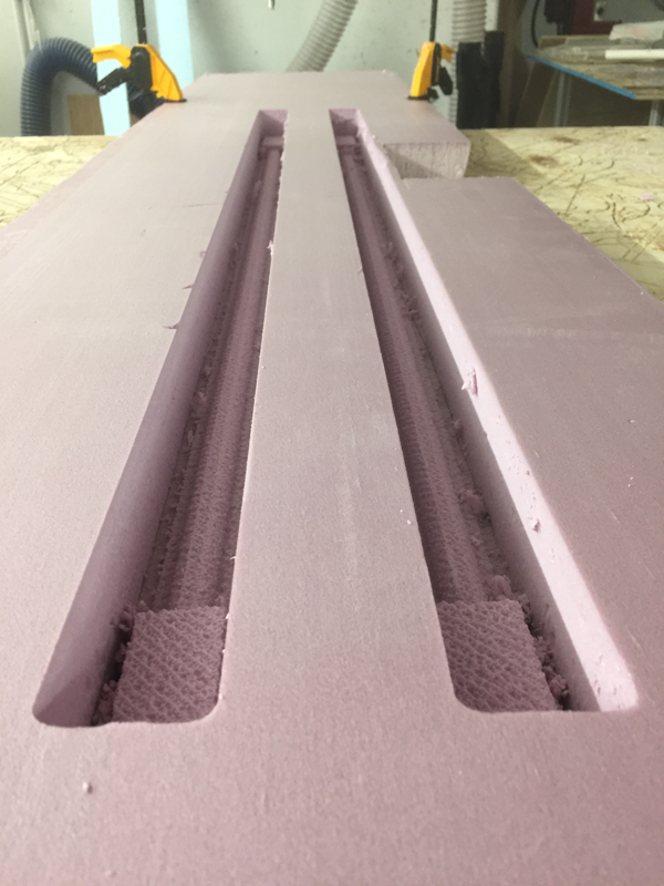
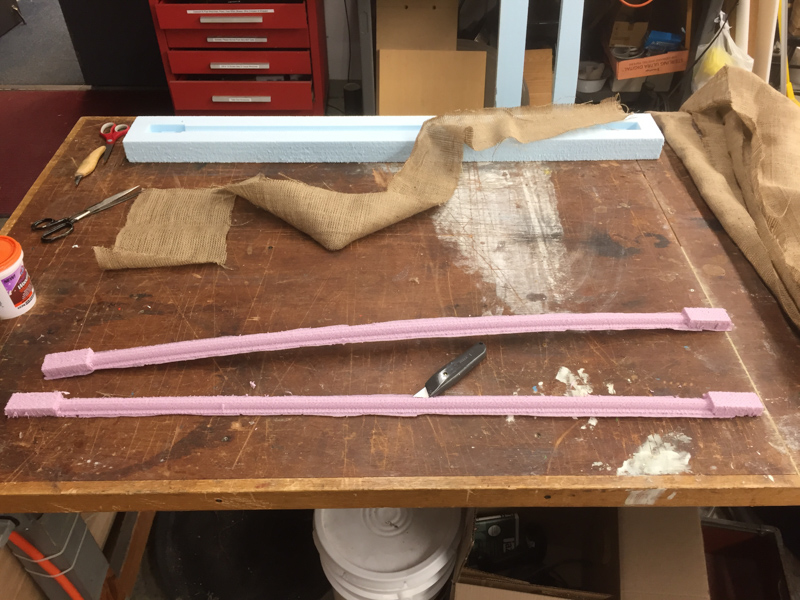
I used basic yellow glue to combine the two halves of the mold core. It did break at one point in the assembly but tape made it easy to keep it together.
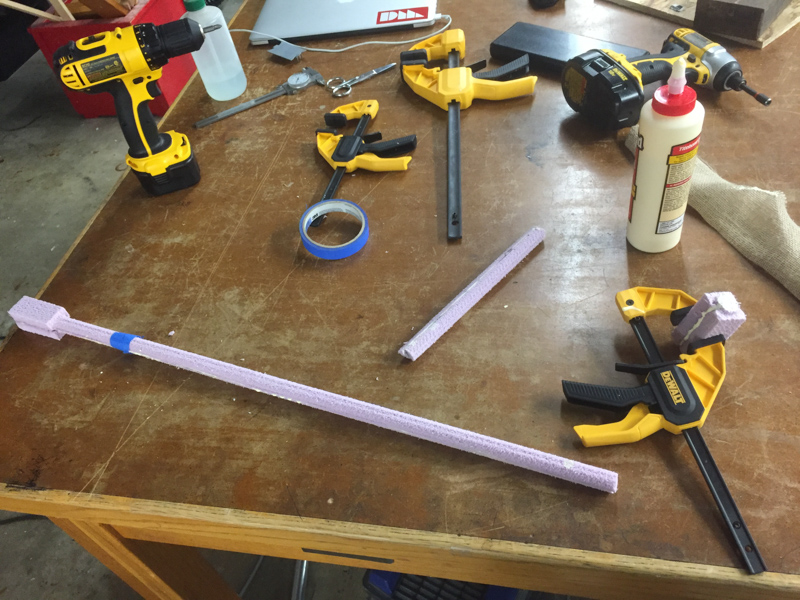
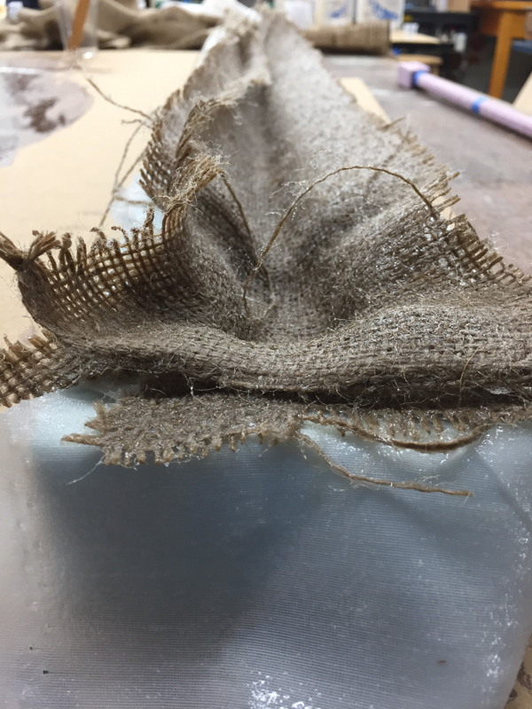
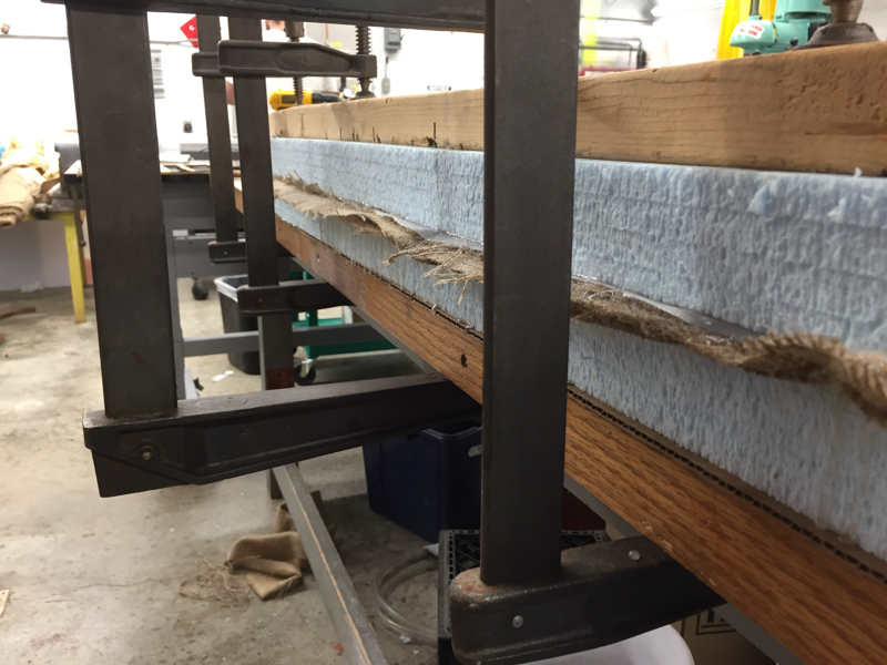
The lay up was a challenge. My goal was to ensure there were enough layers for strength while maintaining the shape of the bar. One of the major issues I encountered which ended up causing a ton of problems was not using the mold release layer (the food grade plastic). We were out of it unfortunately so I tried the carnauba wax-like material we had. In retrospect, Gesso would have been a better way to go.
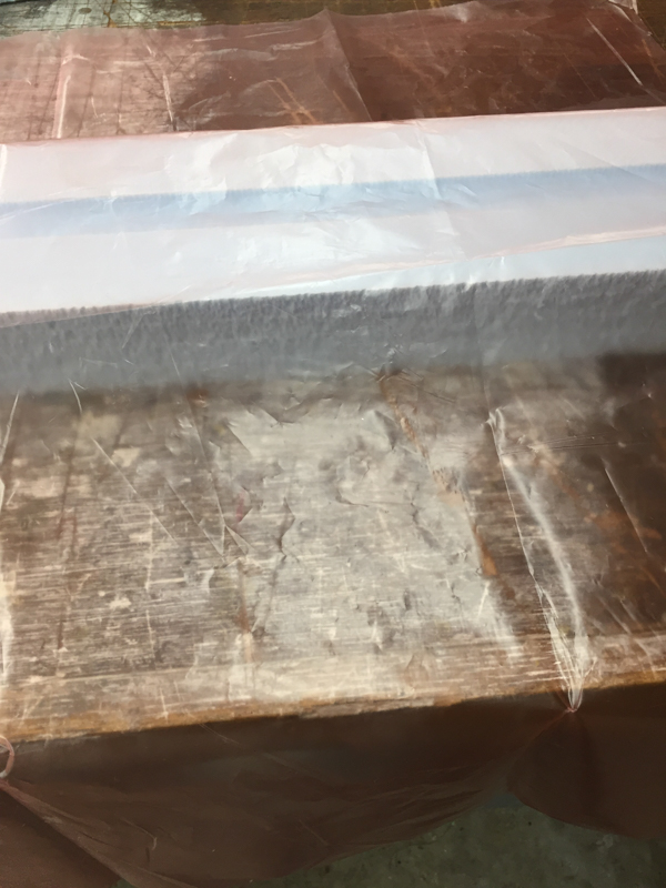
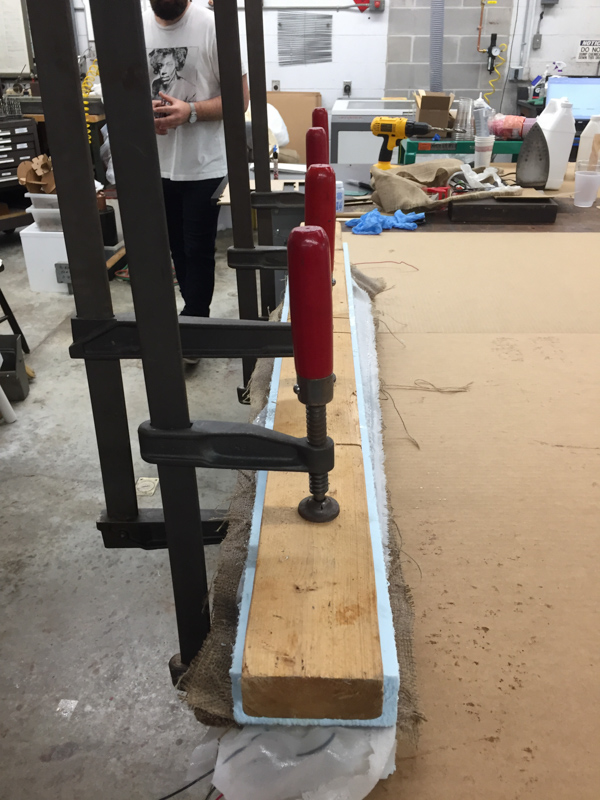
I was lucky there were hefty / long clamps available in the shop to fix the mold and leave it to set.
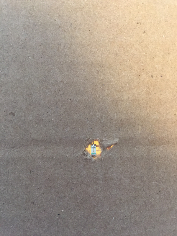
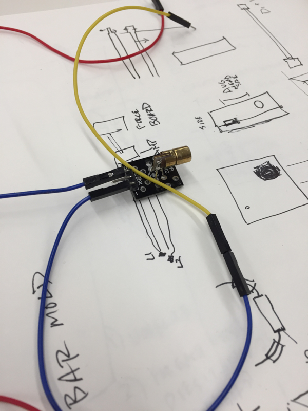
Making the mold for the pull-up bar took a lot longer than expected. After I set the mold, I spent some time understanding / testing the break beam sensor with a photo resistor, photo transistor, and, finally, a simple red LED! The red LED detects a narrow band of light and are very stable which meant it would work perfect at ignoring noise and just seeing the red laser I was using for the breakbeam. Here is a nice overview of this. I was happy to see a significant and easily detectable difference when the red laser was applied, whereas the phototransistor got a bit confused by ambient light.
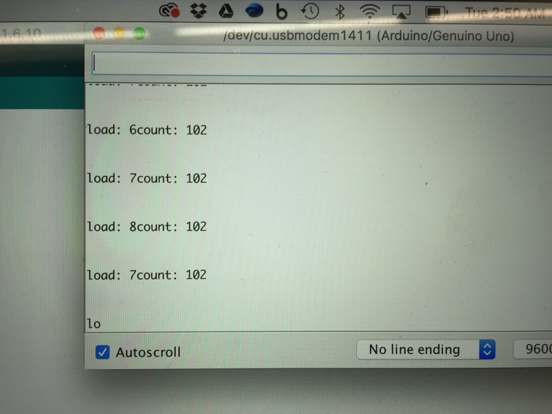
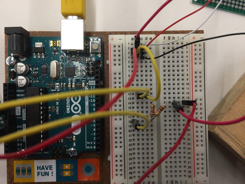
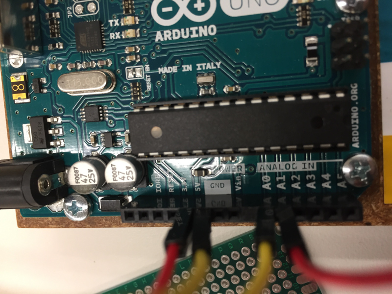
 Next, I tried a new component to get force - a simple load sensor set up in a wheatstone bridge. I set up a half bridge and used arduino to quickly prototype this. I chose Arduino at this point because time was running out and I needed to make more progress.
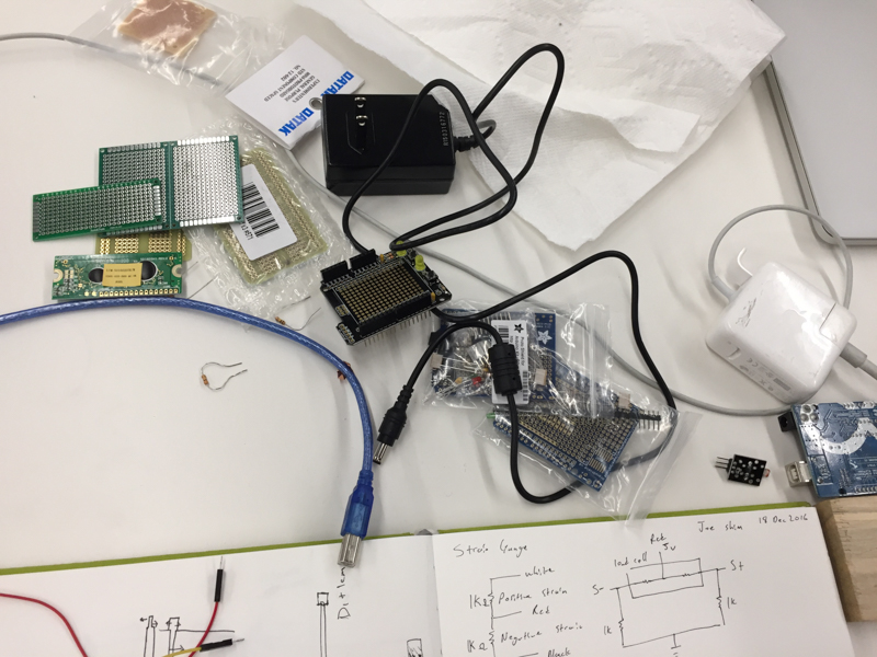
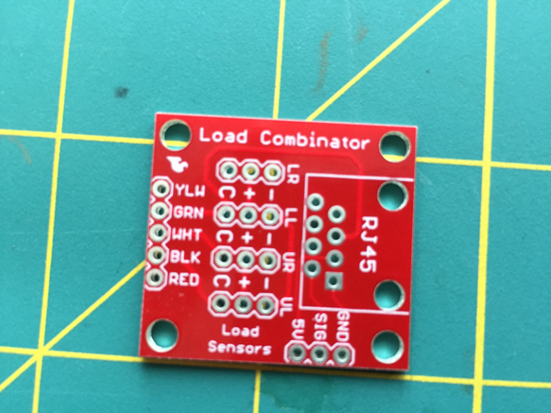
I purchased a few components for the future when I will be reading in detailed force measurements. The load cominator from Sparkfun is a simple PCB that takes in four load sensors / strain gauges and out puts the differential. It makes a wheatstone bridge easy to produce. This guide was super helpful.
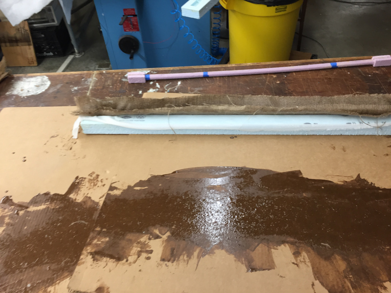
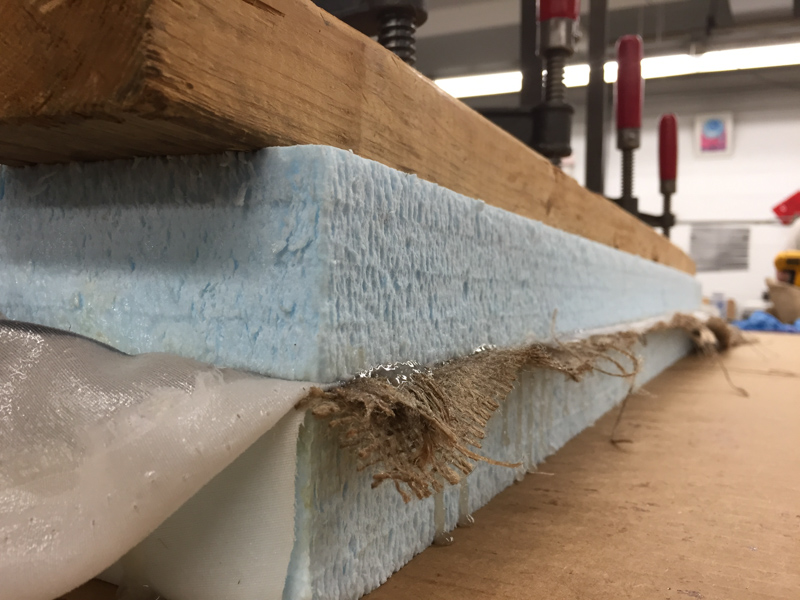
When it was finally time to take my composite pull-up bar out of the mold, I was unsurprised to find that the entire thing was locked by the resin. It took a ton of elbow grease and, eventually, knives to get the bar out.
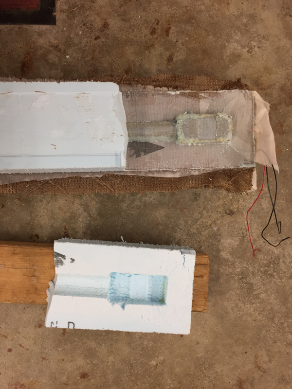
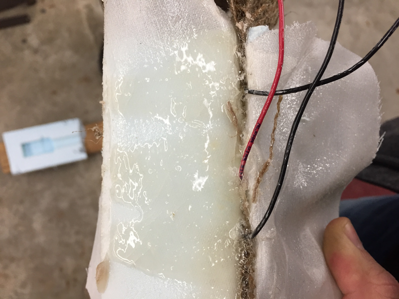
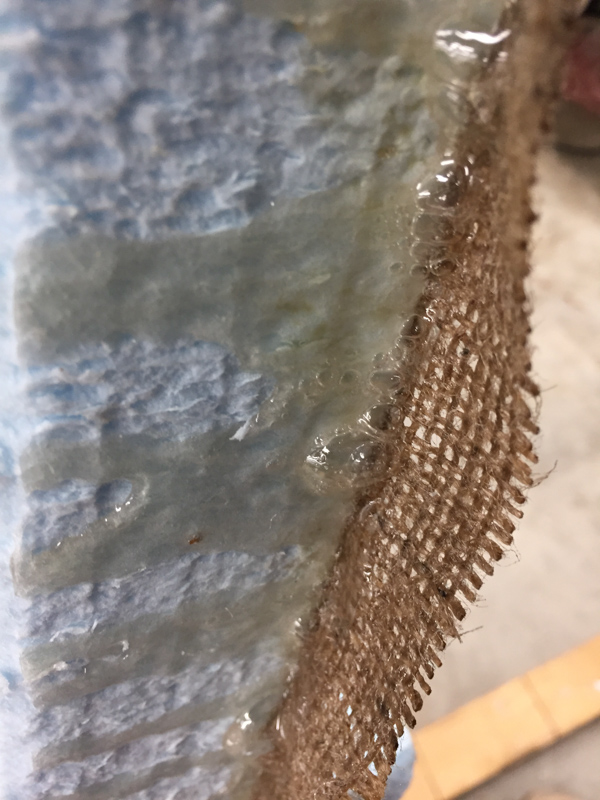
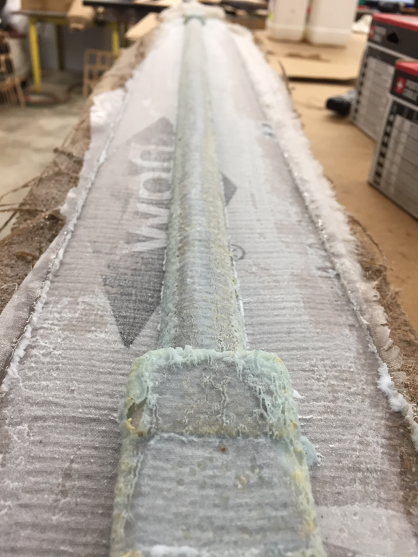
I was disappointed to find that the wax I applied to the mold to create a release layer was totally ineffective. Worse still, it appears to have significantly whicked the resin away from the composite bar. You can see the melted styrofoam adhering to the bar here. The resultant bar was lightweight and strong but not stiff or strong enough to bear a human’s weight. I had to switch to a different overall design.
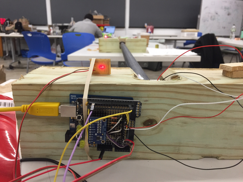
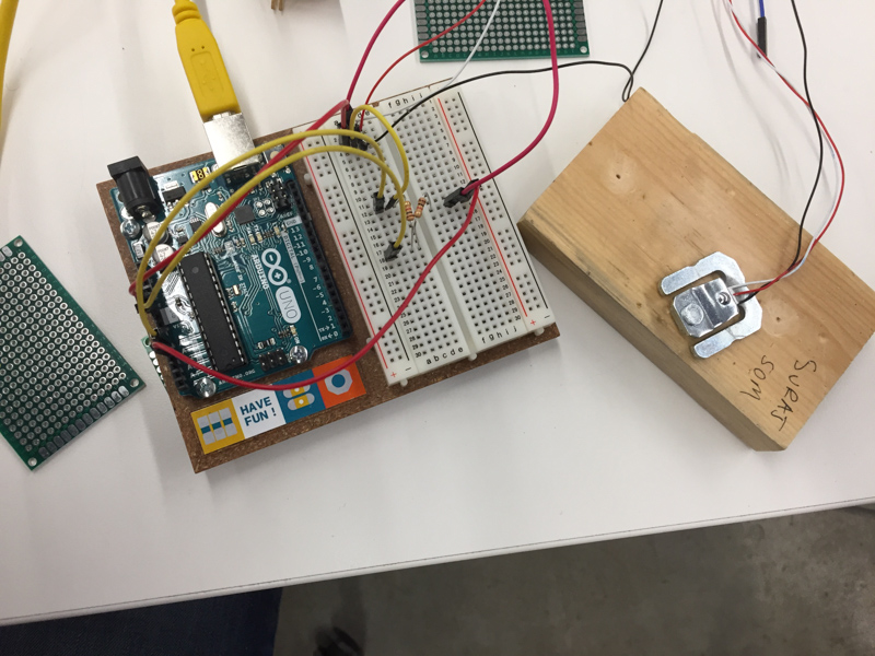
I designed and quickly milled two wood blocks to hold both the load sensors and the new galvanized steel bar I purchased from Home Depot.
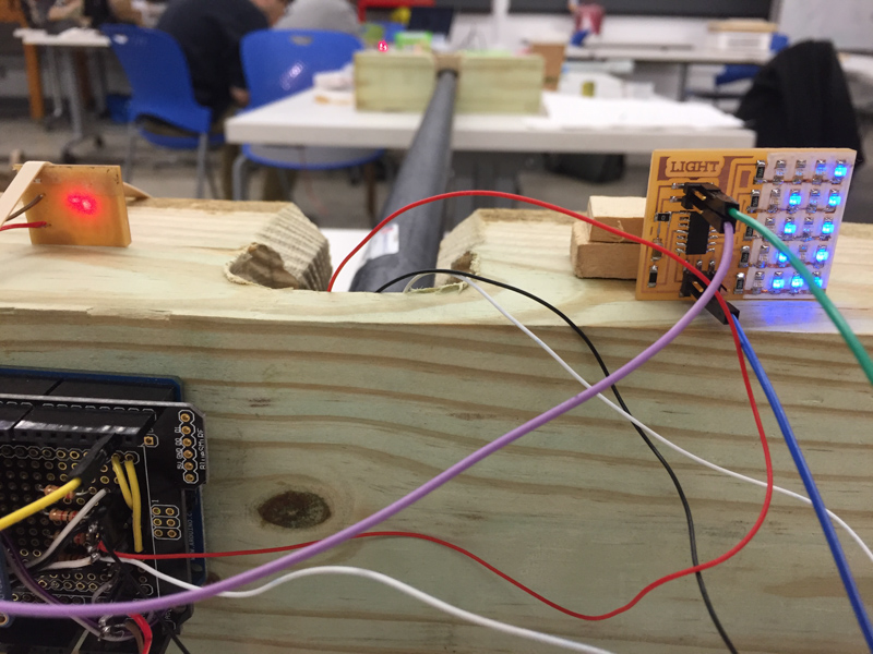
System integration was by far the most challenging and bug filled part of the process. I used to rubber bands, glue, and arduinos to make the process fast. At this point, we were at two nights before the final presentation. The code used a differential measurement from a load cell amplifier to determine whether someone is hanging from the bar. While the bar is activate, the arduino listens to the LED. If the charge threshold is exceeded the count is increased by one. The count is displayed on the charlieplexed LED array which I created from Neil’s LED array board.