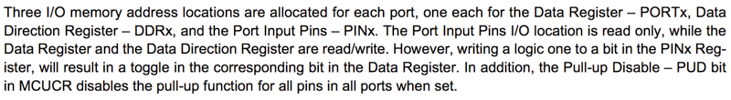
Week 9 - Inputs
OVERVIEW
Measure something: add a sensor to a microcontroller board that you have designed and read it.
My goal this week was to get comfortable with the end-to-end workflow of designing, building, and programming circuits that use sensors. So I wanted to create a bunch of boards. I also wanted to focus on sensing force for a new final project idea.
Round 1 - Temperature Sensing
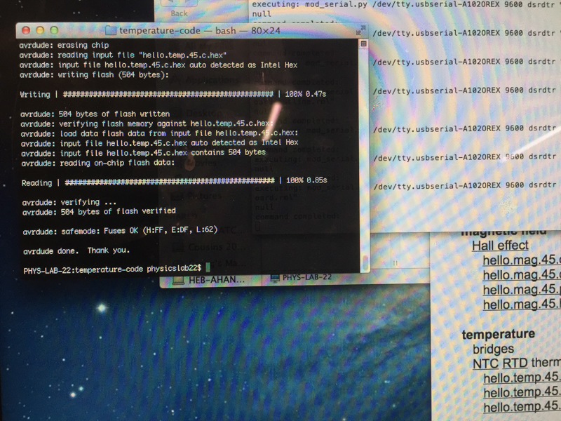
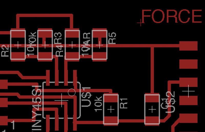
The temperature sensor is a relatively straight-forward design with a clever little circuit called a wheatstone bridge. I selected temperature sensing because it operates in the same way as the strain gauge. It uses a wheatstone bridge to amplify and read in voltage differences which translate to temperature (or force) changes.
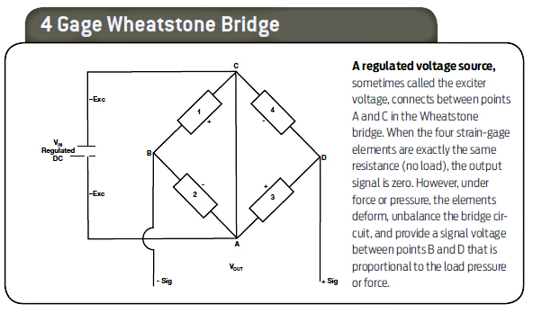
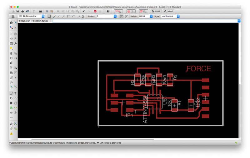
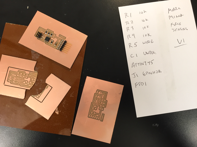
The four resistors at the top of this circuit diagram make the wheatstone bridge. R5 is meant to be the variable resistor (in this case, a temperature sensor).
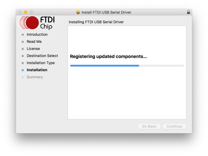
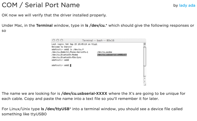
It can take a bit of time to get your environment set up if you haven’t already done it. I’m on a Mac so besides AVRDude, its important to make sure the FTDI serial driver is installed along with necessary python set-up steps for running python programs. Make sure to get the modules that are used in Neil’s programs like PySerial. Pip is an excellent package manager for python that is recommended. Test that the serial driver is working once you have it installed.
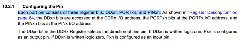
Programming with Neil’s existing boards is straight-forward, assuming your environment is set up correctly and you don’t have issues with your ISP or board. The critical bit for me was really understanding the structure of the C code. There are a bunch of functions set up at the top. If you don’t understand those then the rest of the code won’t make sense.
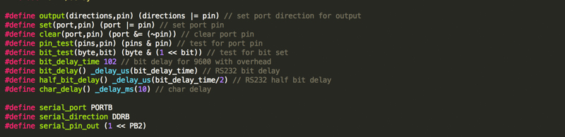
Its pretty critical to read through the register sections of the data sheet to understand the code, as well.
—
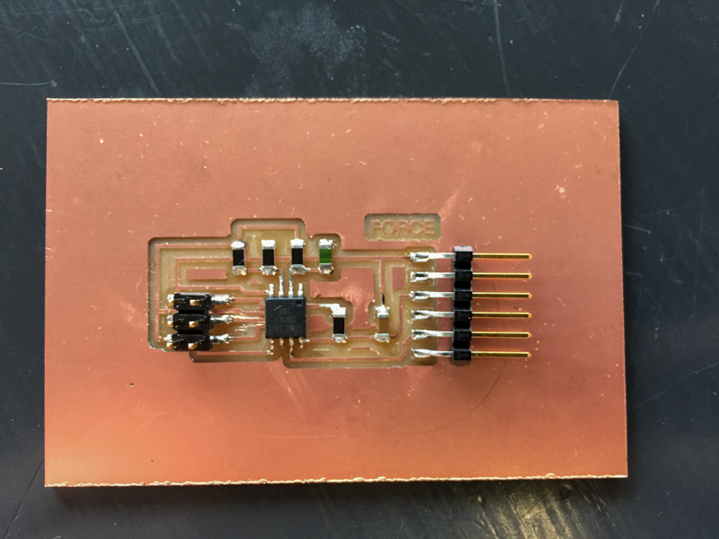
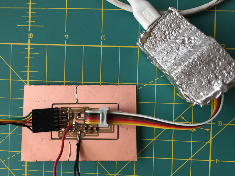
Round 2 - Force Sensing
After I had the workflow down and the temperature sensor working, I adapted it to use a force sensitive resistor. The major issue here turned out to be an incorrectly set-up wheatstone bridge. The resistive tape I used puts out a very limited amount of resistance (about 300ohms). As a result, the wheatstone bridge was never balanced.
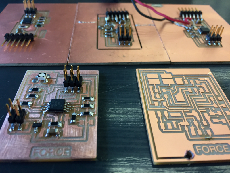
I milled two boards because the first board I milled broke as I attempted to cut it from its outline.
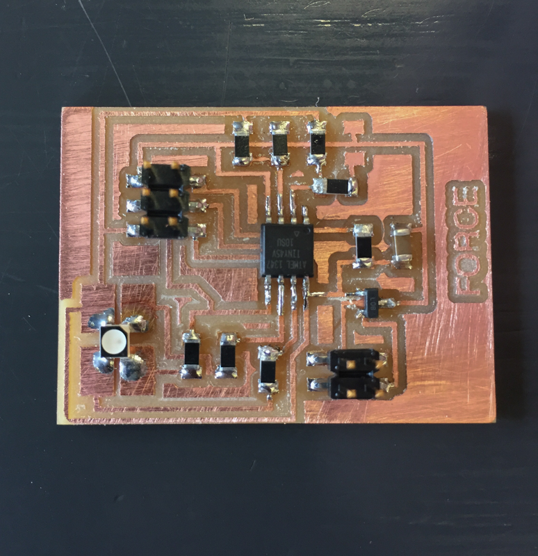
This was a great opportunity to try out my home set-up. As it turns out…cheap soldering equipment is cheap, cheap, cheap. The large, flat soldering head with non-precise temperature would rip up the copper, burn everything around it (including my skin), and generally fail to do a good job. Take a look at the results.
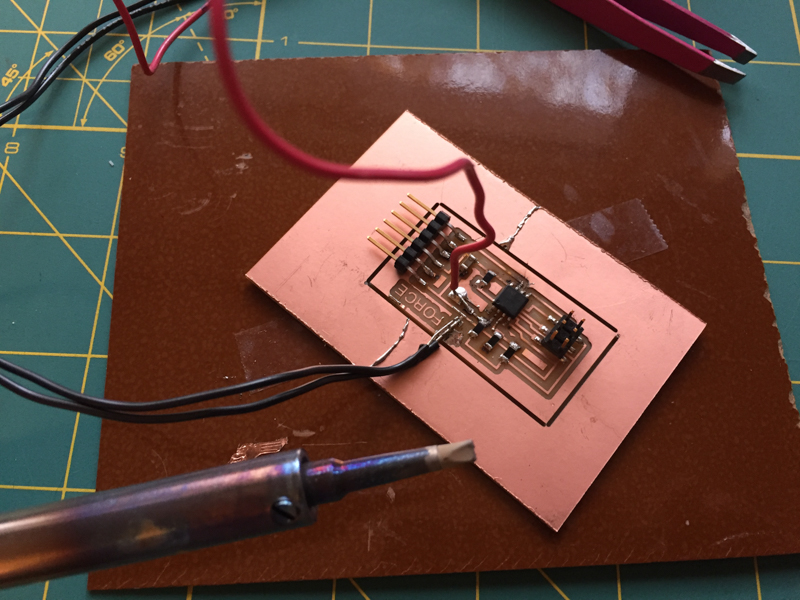
Needless to say, I stuffed a new board at the lab and it worked like a dream.

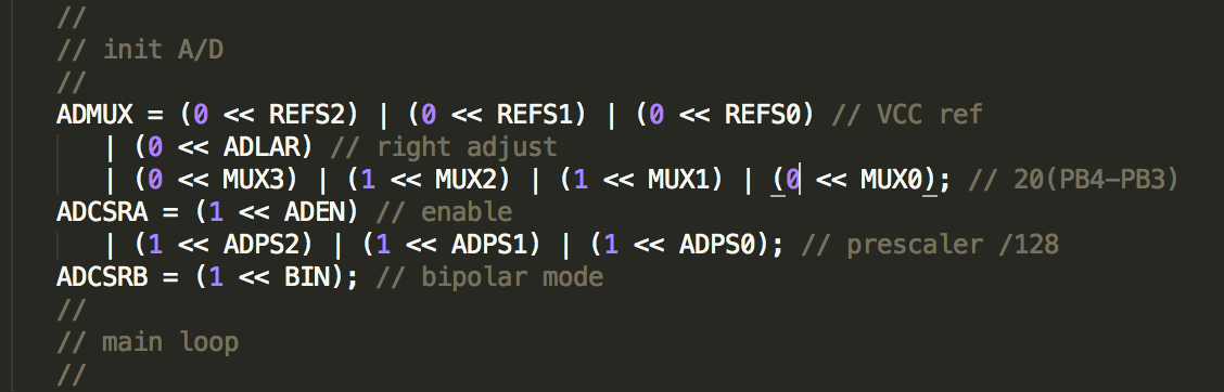
It took me awhile to understand the ADC. The ADMUX, ADCH, and ADCL registers are a short but important bit of code in the C file. This site has a nice overview. But definitely read the data sheet too.
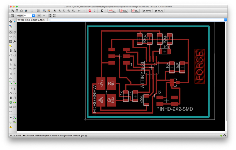
Round 3 — Force Sensitive Resistor + RGB LED
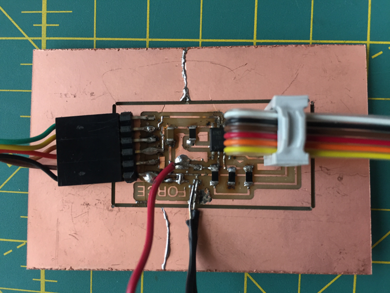
My next step is to add a 10k resistor to the wheatstone bridge so that it is balanced and to include an RGB led for an output. I designed and stuffed the board as part of this week, though I haven’t had the chance to program it yet.
Both boards were milled on the shopbot with the new fab modules (which work great, for the most part). The speed was somehow off for the first board though and the shopbot jerked around as it sped across the toolpaths. The result was a very iffy board in need of serious sanding. While it is a mess, it does work…