Week 11 - Outputs
OVERVIEW
Add an output device to a microcontroller board you’ve designed and program it to do something
Design
My first task was to place the output device in the context of my final project. As part of this, I wanted to think further on the implementation and overall arrangement of the force sensors with the output device.
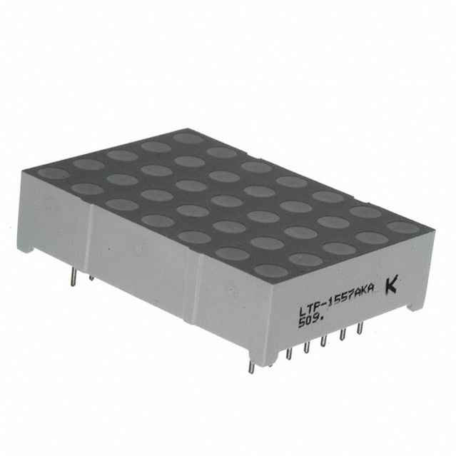
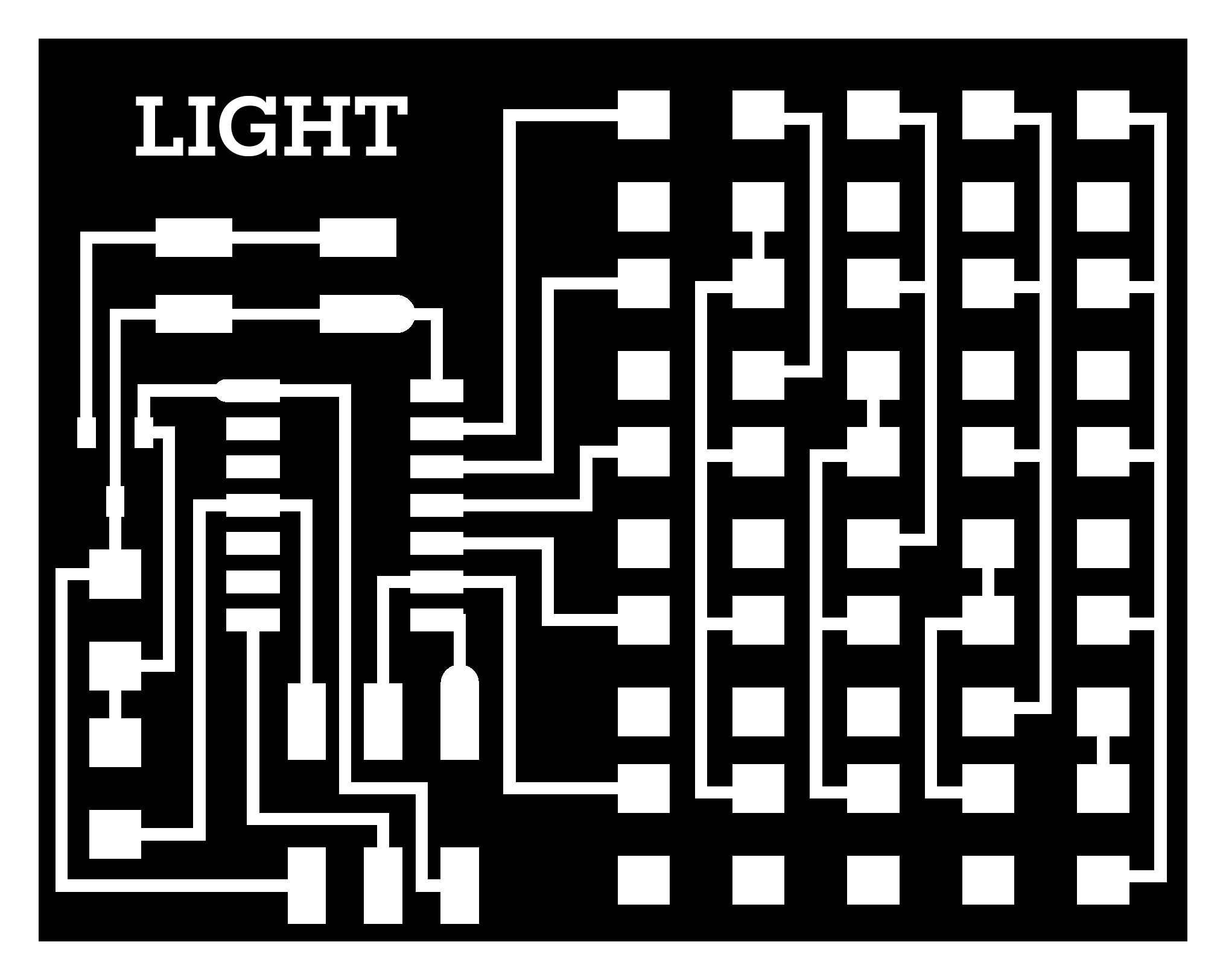
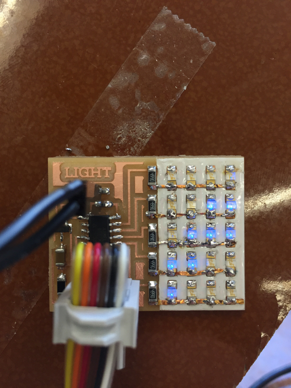
It was somewhat difficult to determine what output device to use. While I knew I wanted to display a count of successful pull-ups for my final project, I wasn’t sure which route to take for output device. I found a great looking 5x7 LED array in the lab with zero documentation or labels. Since it isn’t part of the FabLab inventory, I dug up the data sheet and worked on making sense of it myself.
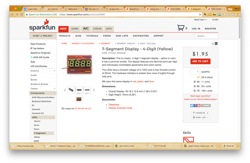
I was also considering a 4 digit 7-segment display component that was also in the lab but not part of the inventory. I found this AVR tutorial and this SparkFun walkthrough instructive on the basics.
I finally settled on just using Neil’s LED array in order to limit the risk involved (trying to learn just a few new things at once).
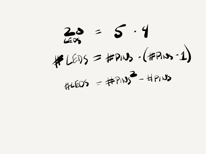
Charlieplexing can take a bit of acclimating to have it ‘click’ but once it does the rest of pretty straight forward. There is a neat little formula, for example, to determine the total number of a LEDs that can be supported based on the number of pins desired.
Here are a few resources I found helpful:
Mill & stuff the boards
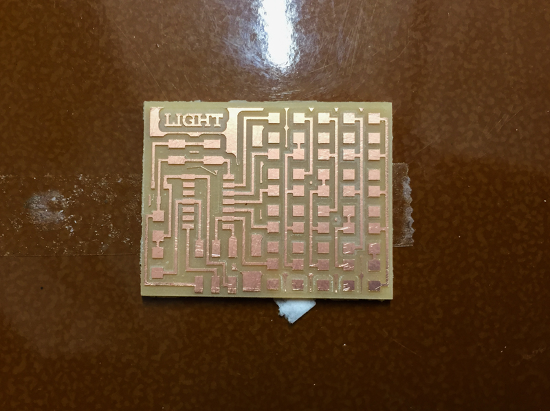
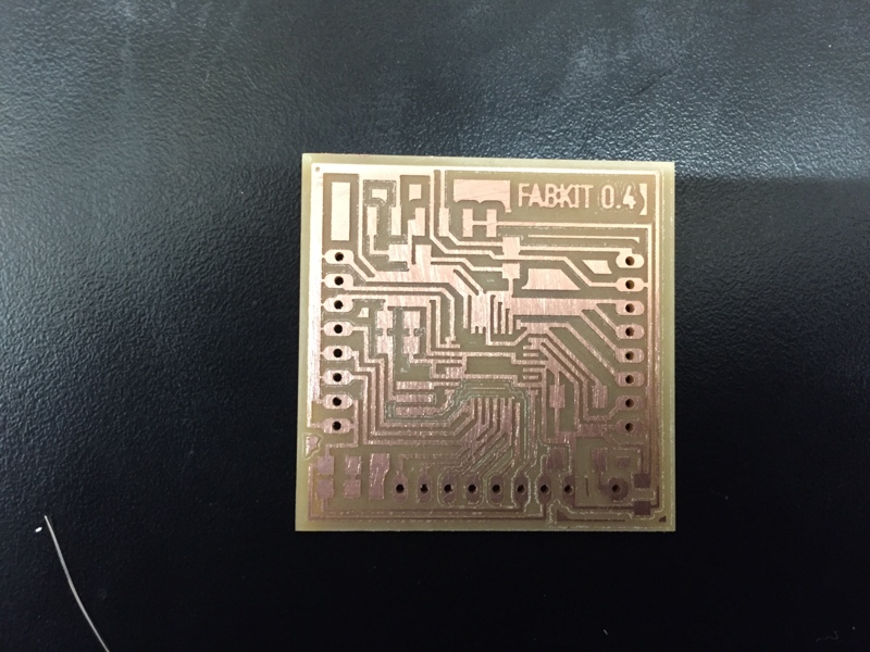
First I milled the board using the ShopBot. I decided to mill a FabDuino board while I was at it. I’d like to leave a healthy reminder for the future to make sure the spindle key is fully turned before you click ‘okay’ when cutting. It is possible to turn it without turning it completely, in which case you will certainly break an end mill.
This design uses charlieplexing and a single-sided board. How is that possible? There is another layer to the board which is created using 3M cast epoxy film over the bottom layer of the board. Unfortunately, this was unlabelled in the lab so I did a quick test with a multimeter to figure out which roll of tape was insulating.
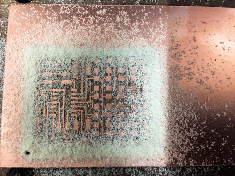
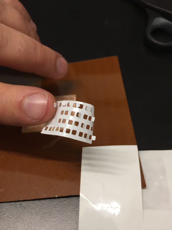
Once the correct paper was confirmed, I used the Roland Vinyl Cutter to cut the mask for the board out.
Removing the little squares from the mask was more than a little frustrating. They are sticky!
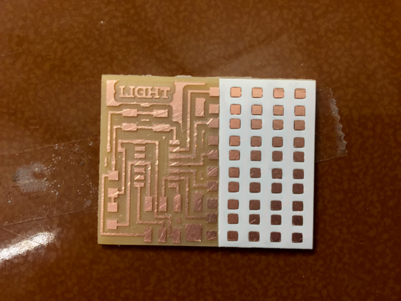
I applied the epoxy film carefully (truth: I went through three of these masks getting it perfectly aligned).
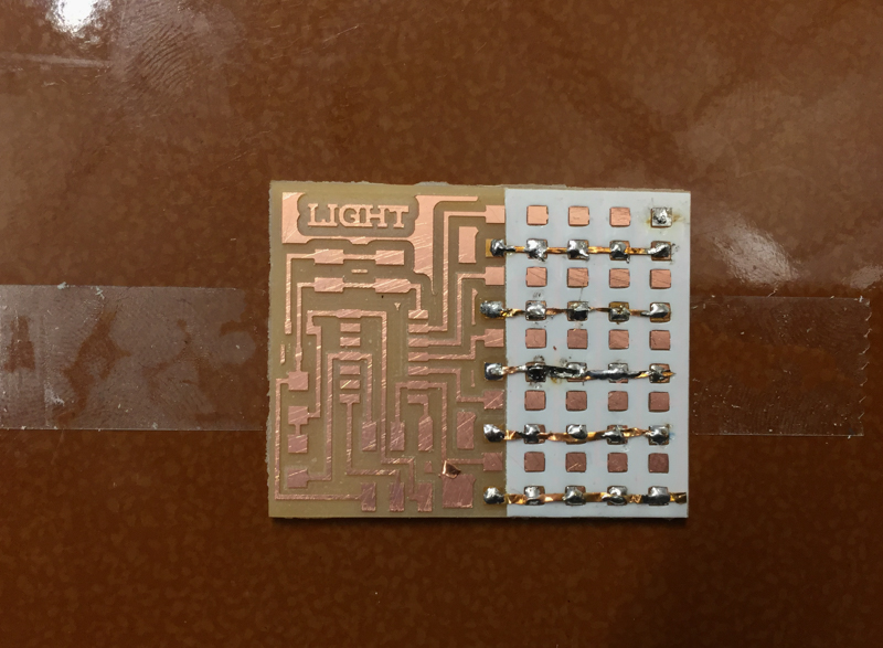
 Finally, I placed some tiny strips of copper to connect the pins and did a solder bump over top.
This design allows each pin to take a turn being a source or a sink of current.
Finally, I placed some tiny strips of copper to connect the pins and did a solder bump over top.
This design allows each pin to take a turn being a source or a sink of current.
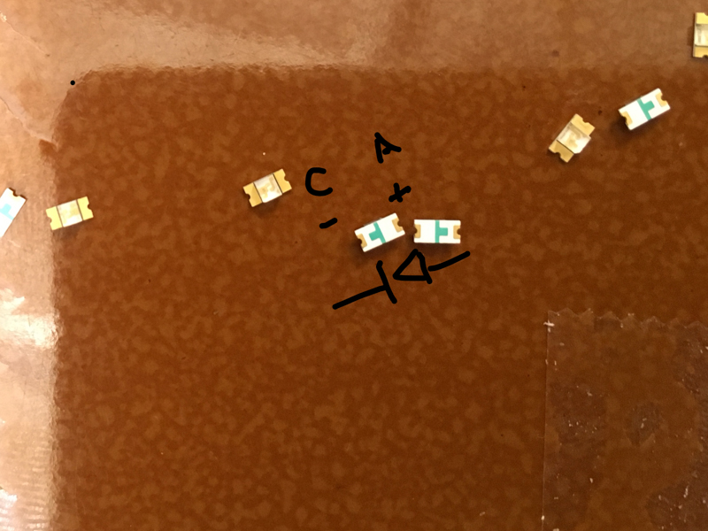
When it finally came time to stuff the board, the only real ‘gotcha’ to keep in mind is that LEDs have polarity (which is actually what multiplexing and charlieplexing hinge on). Make sure you know which side of the LED is the anode and which is the cathode.
Program the boards
Programming the microcontroller to drive the LED array was a ton of fun once I got a bit of experience and exposure to the LEDs.
The first thing I did was to program an earlier board to change the brightness of an RGB LED using PWM.
There were a few resources I found helpful in rounding out my understanding of charlieplexing. I recommend:
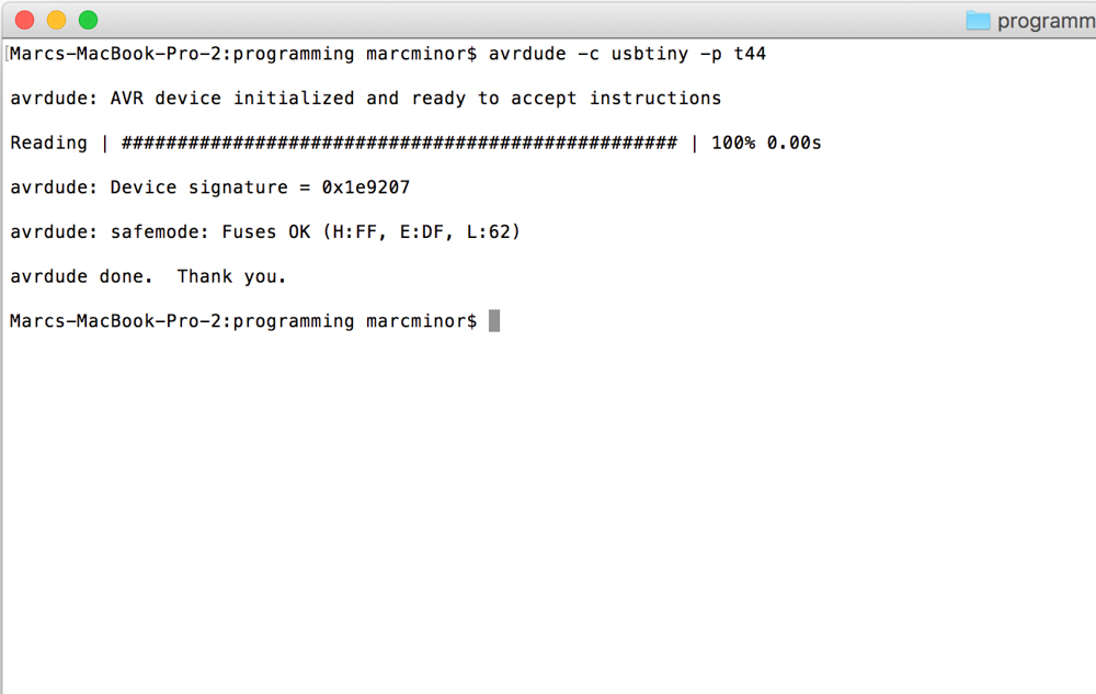
Next up, I programmed the board with Neil’s script. A reminder on workflow for programming. First, check that the new board is recognized.
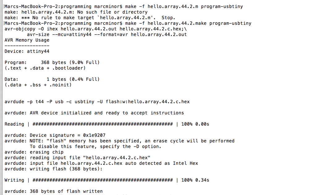
Then, execute the makefile to create a hex file and run the make command again with ‘program-usbtiny’ appended to it to actually target and program the board.
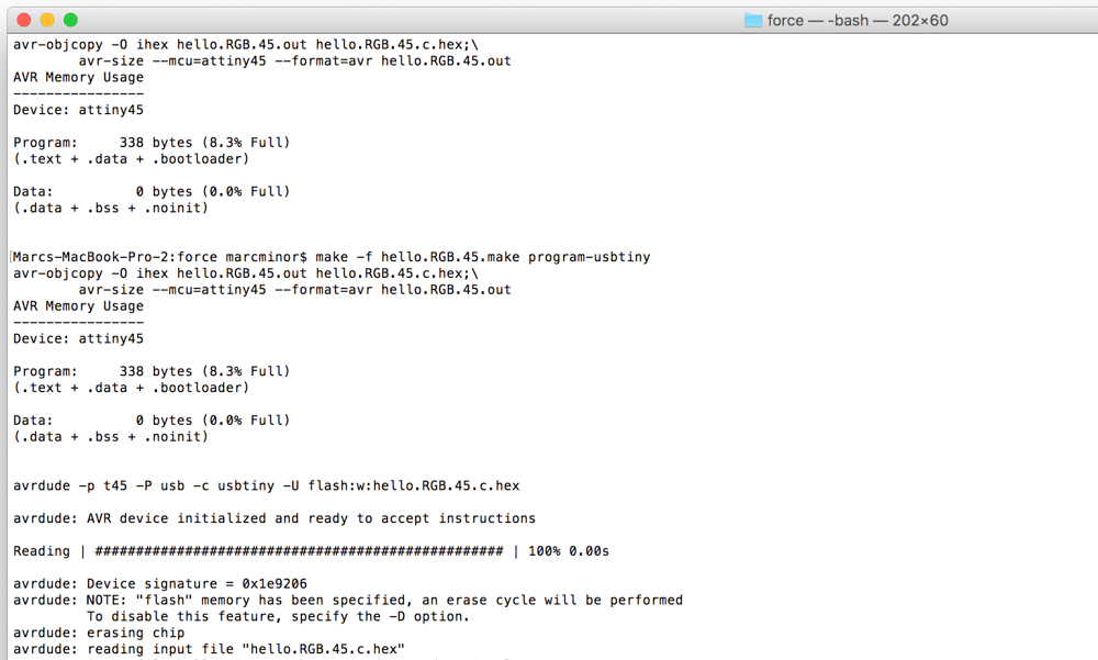
Voilá, some LEDs are now frenetically PWMing with Neil’s ‘flash’ function.
Make numbers
My goal for altering this script was to create the basis for a counter. This is really a prototype for the pull-up count display. I’ll replace the code and hardware with a more significant version in the final project. This is where the rubber meets the road and where really understanding how to target each LED matters.
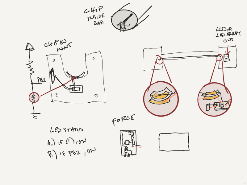
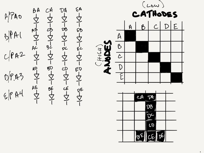
I drew a little schematic to help.
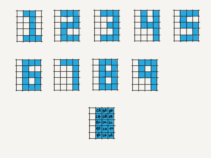
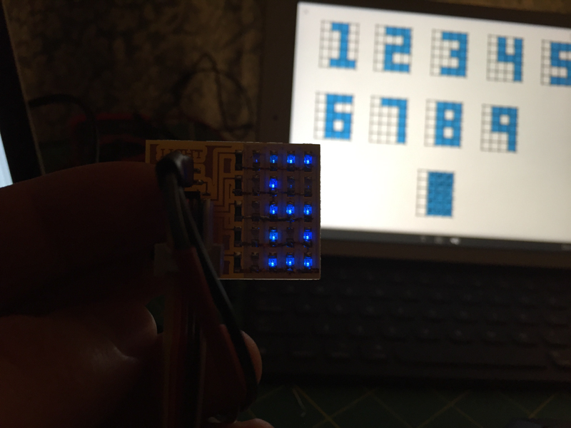
I created a bit of a brute force function for displaying digits called Counter using Neil’s flash function. I’m sure this will get refactored but it works for now.
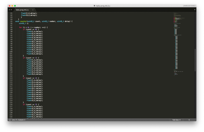
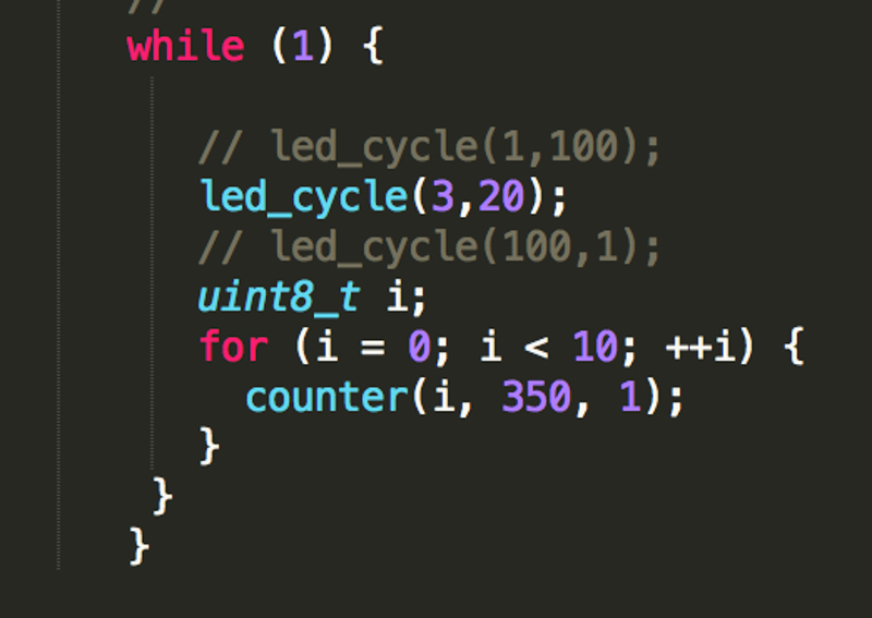
We have NUMBERS! …
Some updates I’d like to make to this code for the final project will be:
- Counter has a session which is activated by force and time
- Counter listens for initial force change (someone is on the bar) and starts a session or ‘count’ based on that
- Counter receives count updates from force board and displays appropriate number for the existing session
- Counter has a time-out function to end a session
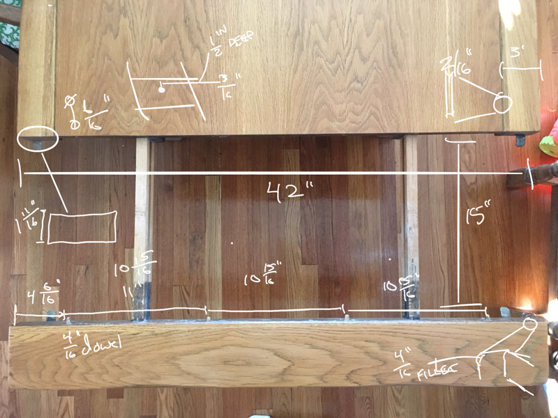
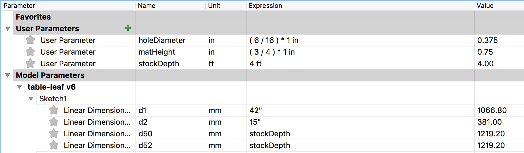
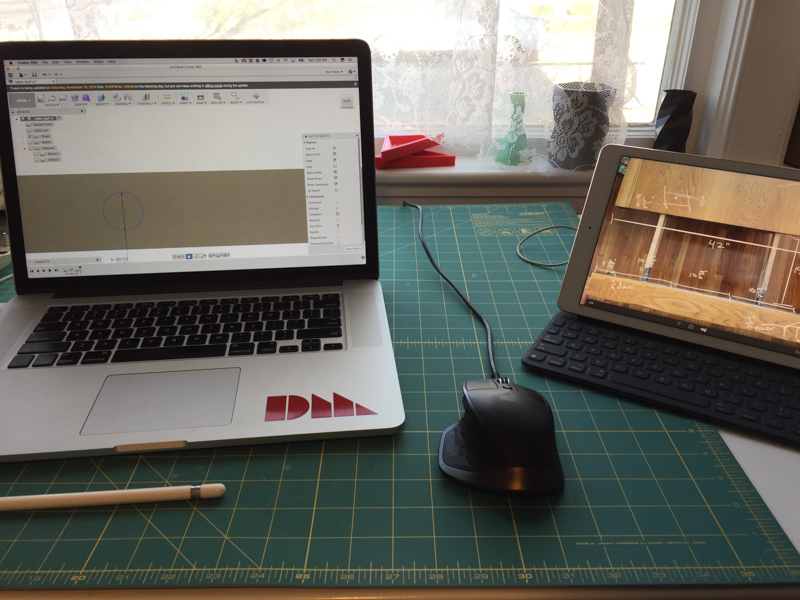
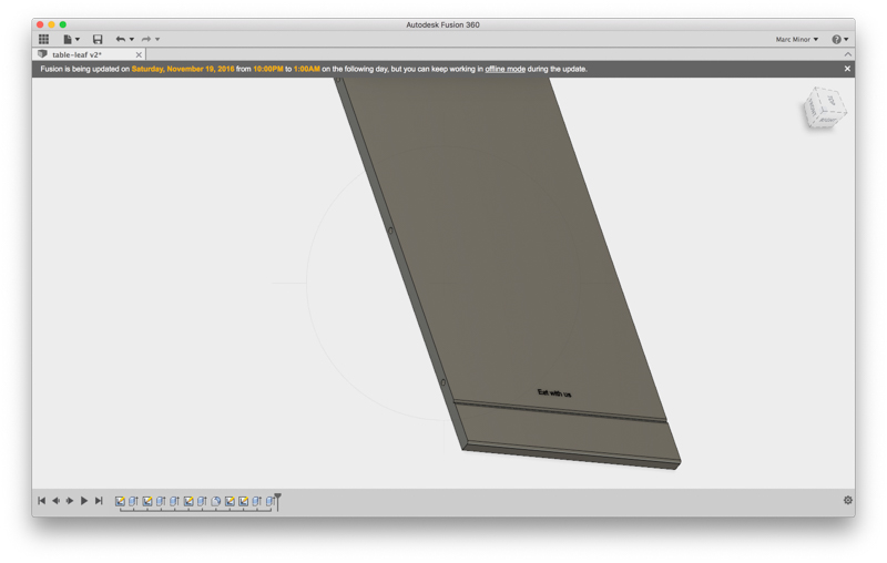
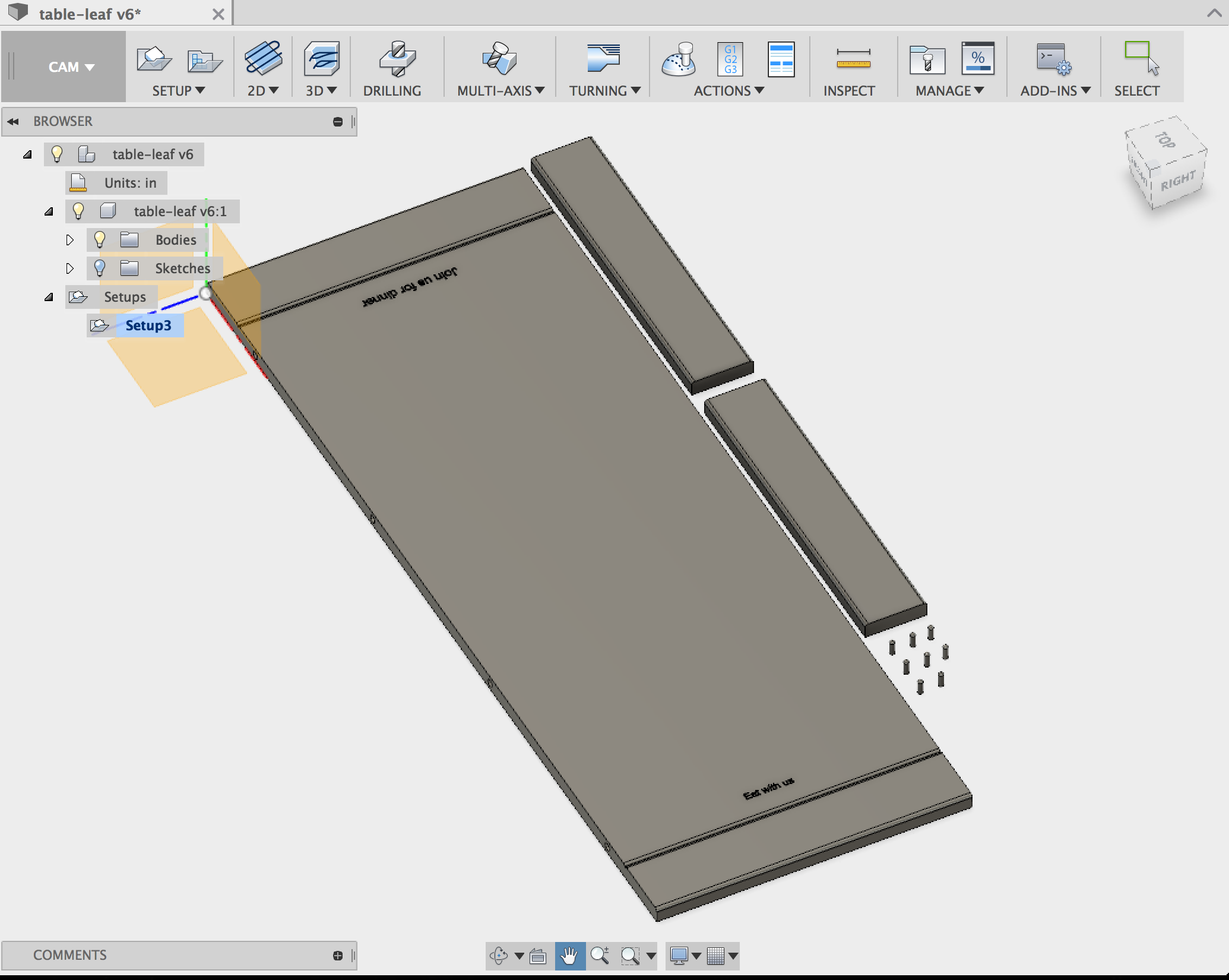
A table leaf for Thanksgiving
I also modeled a dining room table leaf for our Thanksgiving Day feast! This gave me a chance to look into Fusion 360’s CAM system. So far it’s pretty okay but I haven’t milled it yet so don’t have much to say…