Networking over Serial
DISCLAIMER: I did this week early because I had a few exams and other final projects due during this week --- it would have been MUCH easier to do this the actual week as I wouldn't have tried to do what Neil said wouldn't work in the first 5 minutes of class.
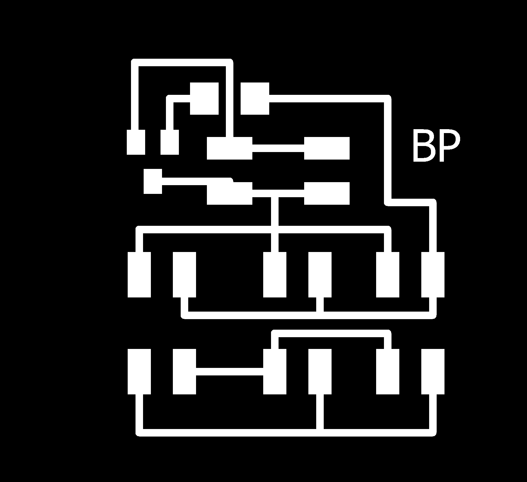
This is a big week for me in preparing for my final project. The most important is that I can talk between a few Attiny44s over serial and to do so I decided to make 3 boards this week. The first is a simple one button board with a serial output. The second is a 3 LED board with a serial input. The third is a breakout board that is used to connect all of the other boards. I realized on my final project that this is probably how I will do things which will keep my routing simpler on each board, the one exception maybe will be the keypad since it needs to be one unit. That said, otherwise the concept of a central serial port connector board, that for simplicity of all the other circuits should also supply a common power and ground would allow each of the other pieces to operate more independantly. I plan to make two of the buttons and test that both can talk to the master over the same serial line. I want to turn on LED1 for board1, LED2 for board2, and alternate LED3 based on total button inputs. This is a simple simulation of my final project networking. If this works there are two directions to do in: 1) build some of the actual final project boards 2) do some RF/Wifi to talk to a distant board (representing a door alarm).
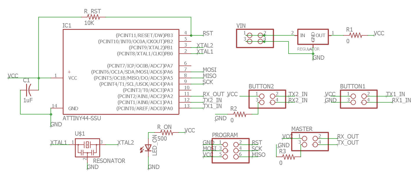
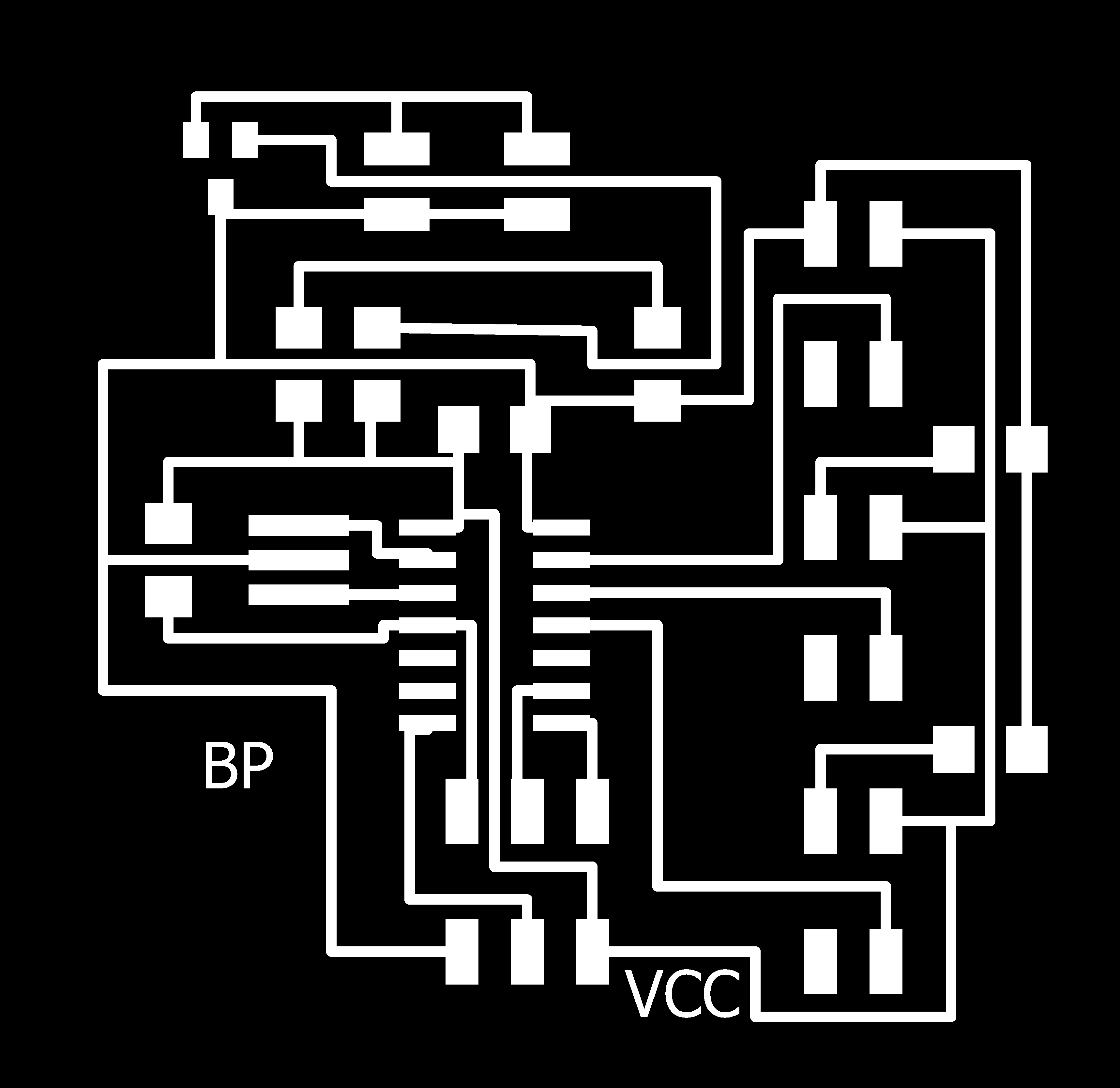
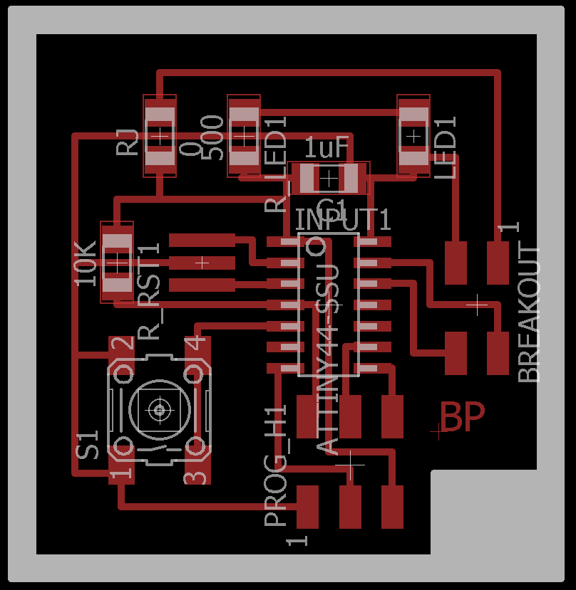
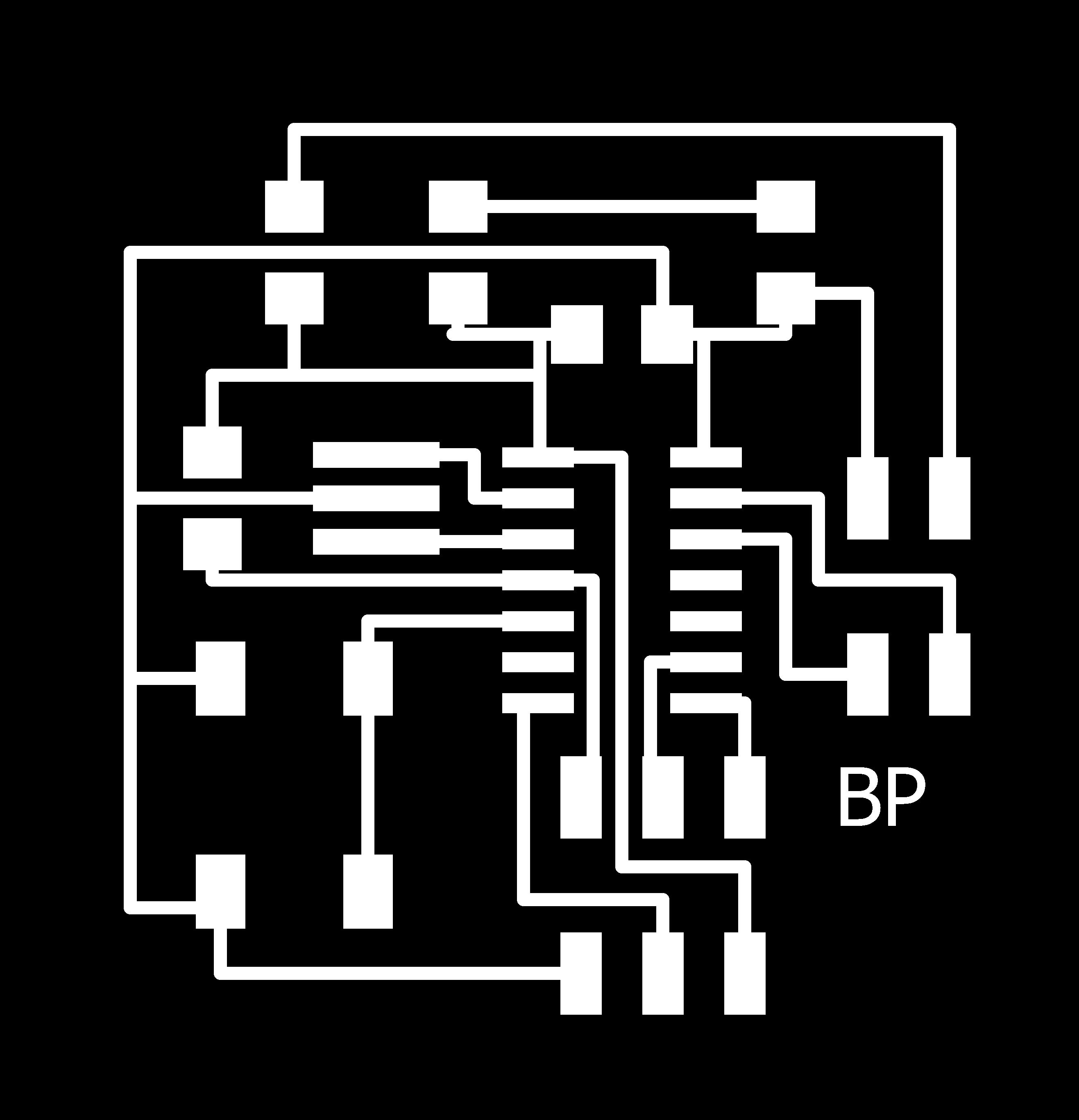
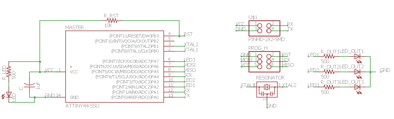
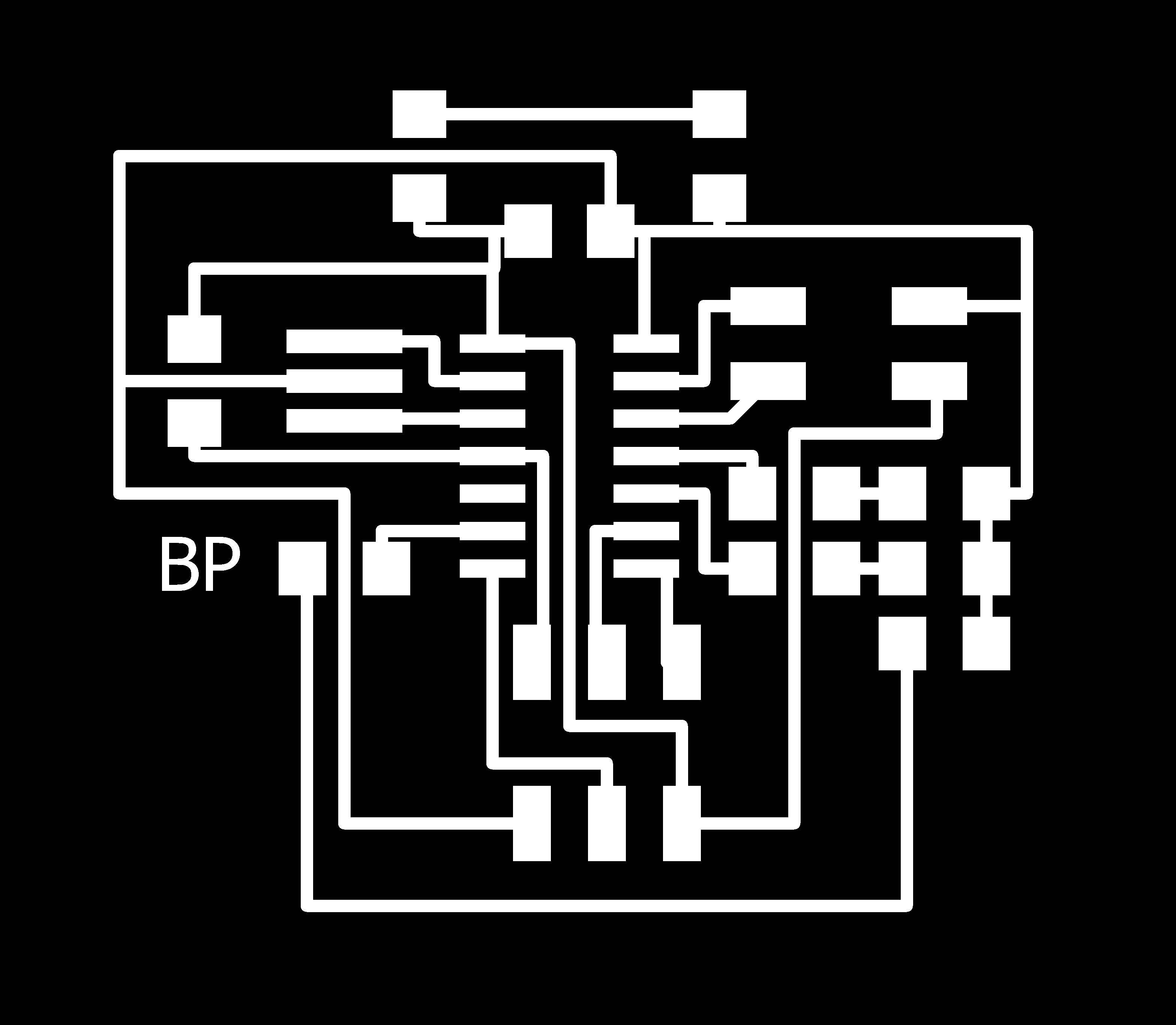
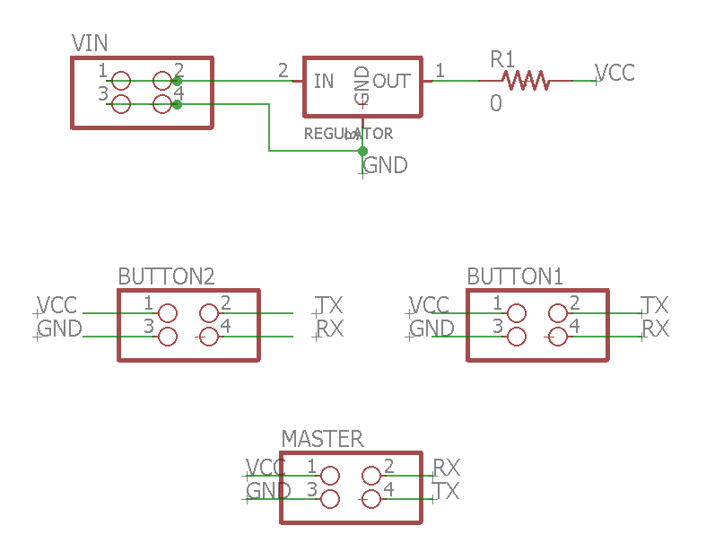
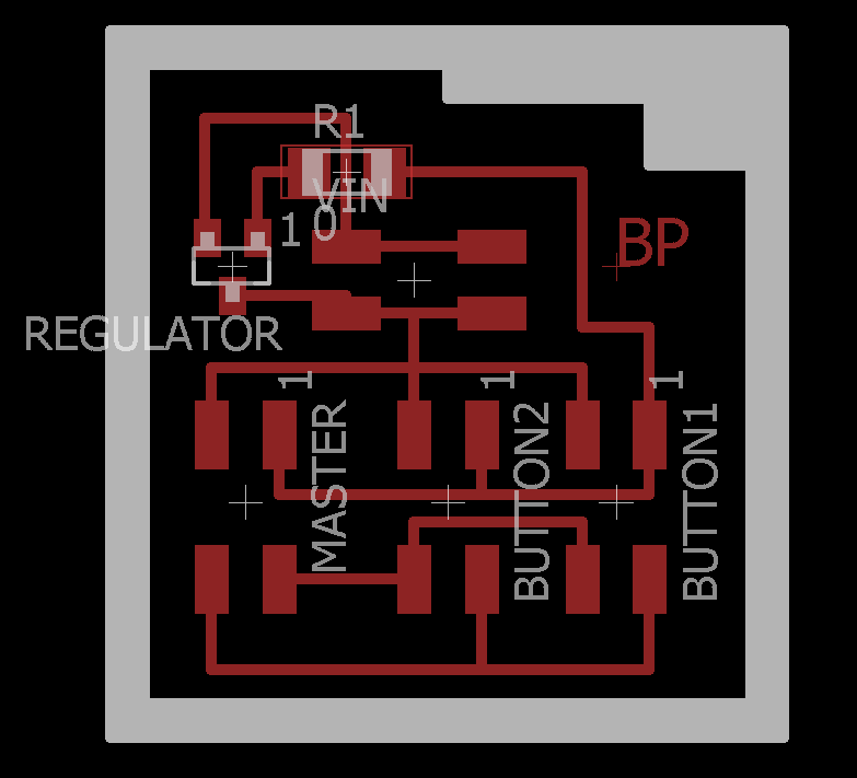
Here you can find the schematics for the button, master, and breakout, and the board files for the button, master, and breakout. Images follow in order of scheme, board, traces, and outline for button, master, and breakout. For those of you following along you will notie that the button board is almost identical to last week except I swapped the FTDI header for a 2x2 header for my breakout!


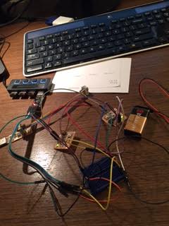
Milling went great as did stuffing all of the boards. But then I ran into a bit of an issue when I realized that the the breakout board had the headers way too close together which made it really really hard to get the cables attached. I ended up kind of mangling the cables a bit and got them to fit but will definitely need to leave more space if I take a breakout baord approach on my final project! Of course once I plugged it all together it didn't work at all but since I was using serial connections I simply leveraged my lessons from the previous week to test the serial data through my computer. When I plugged the button boards into the computer to my pleasant surprise I was that everything was workign great. I had programmed one to say 'A' and the other to say 'B' to differentiate them and they were doing that! :). I also loaded Neil's hello.ftdi.44.echo.c to test the serial read capability of my master board and that worked perfectly as well. That said at least the power lights worked... and it didn't even work with just one of the button boards plugged in. My assumption then was that the error had to do with the breakout board (it turns out there are many problems with this breakout board including the fact that the master RX should be connected to the button TX and vice versa which isn't the case right now but as we will see there were many more problems in general).
Therefore I connected everything through a breadboard and tested things one at a time. I found that it still didn't work with both of the buttons attached but if I only attached one button it worked fine and would read the 'A' or 'B' and react appropriate. At this point I freaked out because I assumed that while it is possible to read from multiple boards over one serial line it would be impossible to write with multiple boards which is what I needed for my final project (this turned out to be true) and therefore my final project would be impossible (this turned out to be false as there is always a work around).
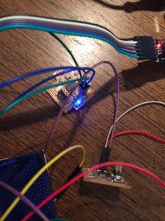
My next effort to make things work was to try to use a logical OR gate to combine the signals from the two button boards as my assumption was that they interferred with each other a bit and maybe I could decouple the interference with a logical OR gate. Luckily I have a couple LS74 series NORs (02), and inverters (04) and they are through whole so I plugged those into my breadboard as well. By a stroke of luck the ones I have lying around are also 5v compatible so it was super easy to wire up with a couple jumper wires. I tried the NOR (with and without an inverter) to see if NOR, or OR would work. None did. I started to really feel like this was going to be a total failure. I had to remind myself that I had already technically completed the week (I can talk from one board to another) and I can get away on my final project with using an AVR with more pins if this all fails so it was all going to be ok! Nonetheless I trudged onware looking for a new solution.
READ THE SPEC SHEET FOR THE PROTOCOL YOU ARE USING. I read the one for serial connections and immediately felt like an idiot. TX holds the line high until it is ready to send a message and sends a low pulse as a notification. Clearly these approaches were going to fail as the constant high from the button not in use would always clobber the data from the button in use. So I went back and tried NAND gates with and without an inverter. Just to double check I passed one through an inverter twice and it worked fine. So then I hookeded up the NAND gate and it still failed. What it did was blink the third LED occasionally which meant it was getting some noisy data through constantly -- which is weird. I decieded this approach in general was never going to work. I got grumpy, then I had an idea: when I was thinking of using logical OR gates, Rob said I could make one with an attiny. I had tried first the hardware gates because I was worried about delay though the attiny, but what if I created a serial logical OR gate with another attiny! In theory if this would work I could have a 12 input, 1 output serial logical OR gate with one attiny44. Then I could basically use that as a data bus and pass the info from any and all of my sensors to the main control board for my final project. So I decided to try to make both of the master TX and RX lines into two RX lines and hook each one up to a button board's TX line. Again I did this through the breadboard for testing purposes. I removed the while loop wait from Neil's getChar function and instead tested for that pin condition in my main loop and called the rest of getChar when that condition held. It didn't work - I died a little inside. But then I realized that the condition on the while loop is when we are NOT supposed to keep going. I added a '!' in front of my condition and it worked! IT WORKED! :) Here was my working code for the button and the master board! And here is the makefile. Make sure to change the name of the program in the makefile and then as in week 11 you can simply run 'make' then 'make program-usbtiny-fuses' and then 'make program-usbtiny' to program a board! Again you may need to change the avrdude variable to the path to your avrdude instalation.
Data bus board here we come! You can click the image below to play a video showing the two different inputs causing different lights to turn on! For anyone wanting to know how I made such a small embedded video the trick was to use HandBrake to convert my iPhone video down into a small size and then I simply used the HTML5 video tag!
I didn't have time to stuff and test a full data bus breakout board design but I did come up with a quick design (board, schematic) which in theory would work as a bus for the two buttons and the master. If you wanted to code it up you should just take the current master code and basically instead of powering LEDs when you see things instead send the data over the "RX_OUT" which is connected to the RX of the master and then the master can read from either button board!