PCB Milling / Soldering
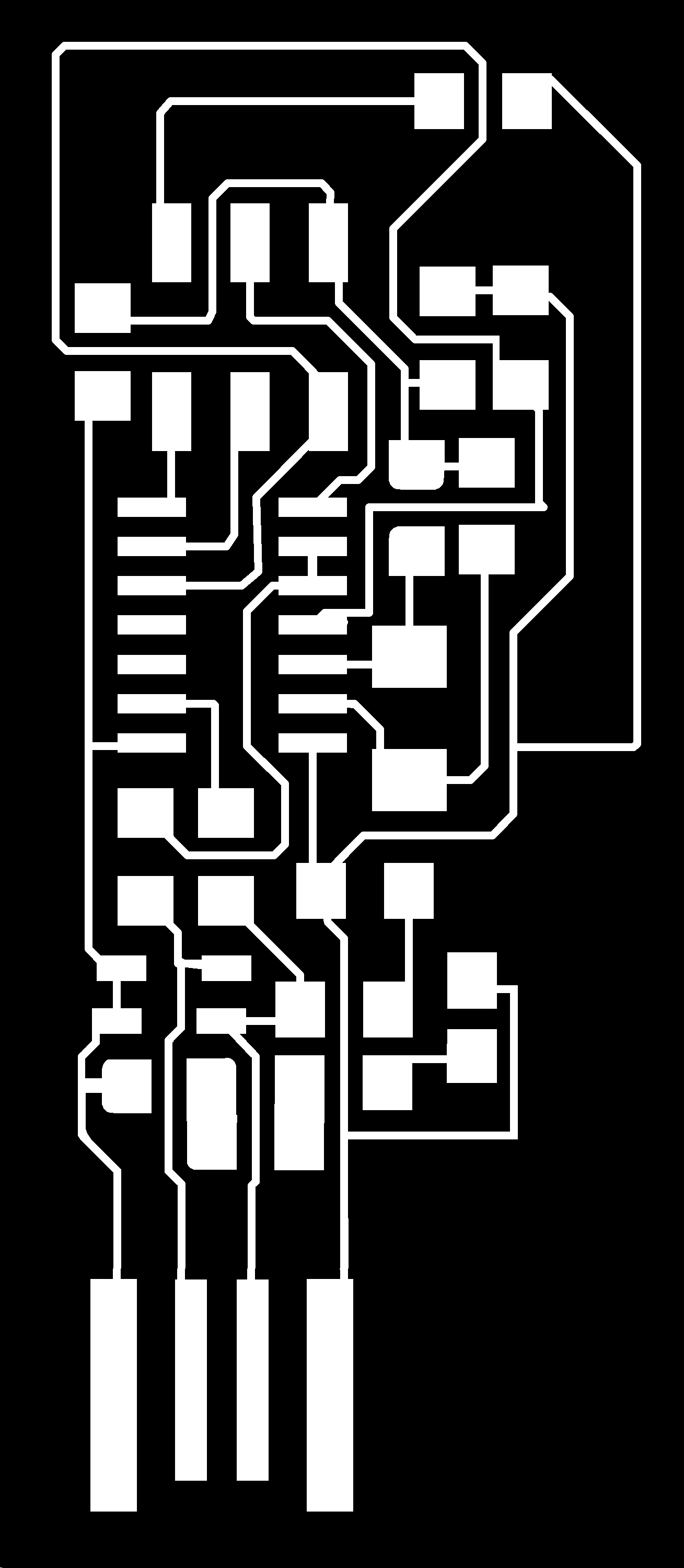
This week we were asked to mill the microcontroller programmer board and surface mount solder on all of the componenets. We were provided with already completed png files from which to mill. Neil showed us the default layout, an adjustment to make the usb a part of the board directly, and another adjustment that has a snap off part to remove an extra component after its done. I decided to make one adjustment to that final iteration -- an an indicator LED for power to the circuit!
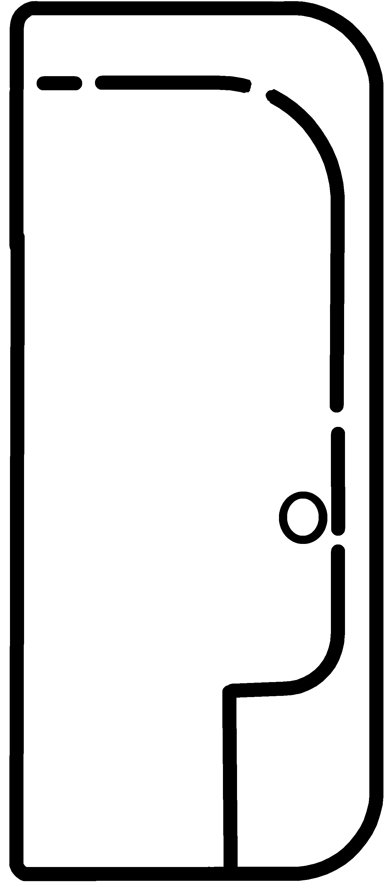
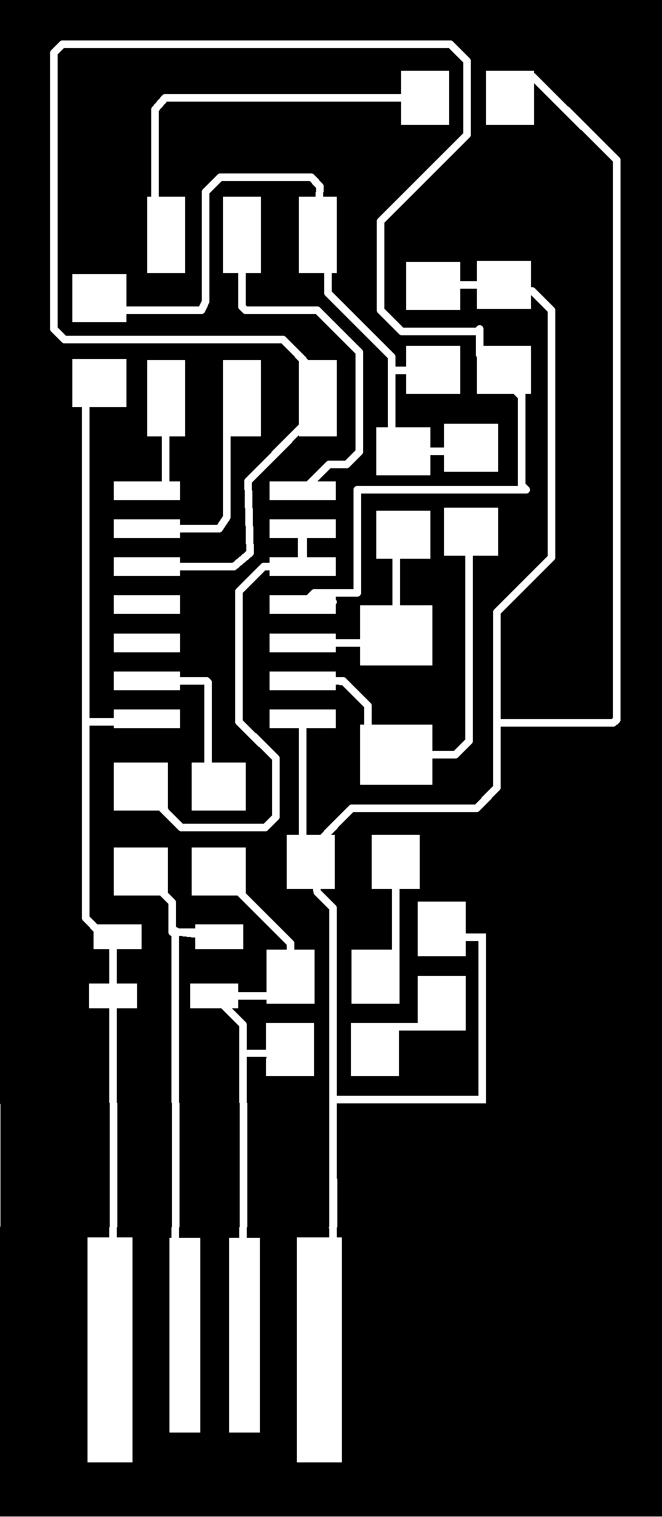
In order to adapt my board I simply added in a resistor and LED in series from power to ground. I did this in Microsoft Paint by simply copying and pasting some pads from elsewhere in the design. Super easy. The trick was making sure that the outline and traces files were exactly the same size in pixels. I based my board off of the snap off design as described by Valentin . I used the schematic posted by Andy to figure out that two of the USB pins are just power and ground (more on that later). I had to remove the circle cut through the board to have space for the LED. Changed files below:
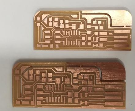
Onto my first pass. Unfortunately, I didn't hold the bit down to the board when I tightened it so it raised a little and didn't cut all the way through. This is easy to tell because there isn't any white dust. So I had to cancel the run and then re-zero the z on the bit. With this fix the second pass had the telltale white dust to say that it was cutting through the copper and a tiny bit into the substrate below. Below you can find pictures of when it first came out and when it was vacumed off (looked so nice!) and after I duburred (btw be careful I deburred a little too hard and you can see some streaking in the copper).

I made one big error! When I edited the file in paint I lost the correct DPI on the image for scaling. Unfortunately, I blindly used the DPI from Neil's original picture not Valentine's assuming they would be the same. I was wrong. You can see below how the chips won't fit because the leads are about 15% too big and spaced too far apart! :-(. I have fixed it on my files below but make sure the DPI is 1500 if you plan on reusing these.
Also upon further review I realized I had connected one of the data ports to ground not power, so my power light was actually a data light. So I had to go back to the drawing board and go back to paint and fix it. This added a bunch more 0ohm resistors in the bottom of the board crowding it a bit. To make sure it could still cut I had to move everything a tad closer together and round some corners on pads to get fabmodules to work right (I later learned rounded pads are generally a good thing for fabmodule processing). The updated design also has some combined large pads to save space on the 0ohms. Time to send it back to the mill! It came out of the mill looking great -- you can see how much smaller it was than the first one below.
That said if you look very very closely you can see that in the upper right two of the pads are connected to the wrong leads -- two cuts weren't made! :(. Also the perfectly round outline cuts take a long time. So after a little bit of rounding two more pads and some straightening out of the edges, it was back to the mill for another round of milling. Updated design can be found below.
Now it's time to stuff the board! I decided to start with practicing on some scrap (aka the two boards that didn't work out) which was a great idea. In general I found you need to add less solder than you think and that you have to be really steady because often the solder looks great but is actually crap once you look at it under the microscope. Going slow and steady also prevents you from having to redo or remove solders which is a real pain (I practice some of that too and decided that I didn't want to do that in realtime if possible). That said, I didn't take a smart approach to the order of soldering. I did the attiny44 first because it had the smallest leads but then in trying to the middle pad for the 2x3 pins I had to get really close to the attiny44 and not only ripped off a pad accidentally but also got the attiny44 too hot and melted it a bit -- so it was time to scrap that board and mill again.
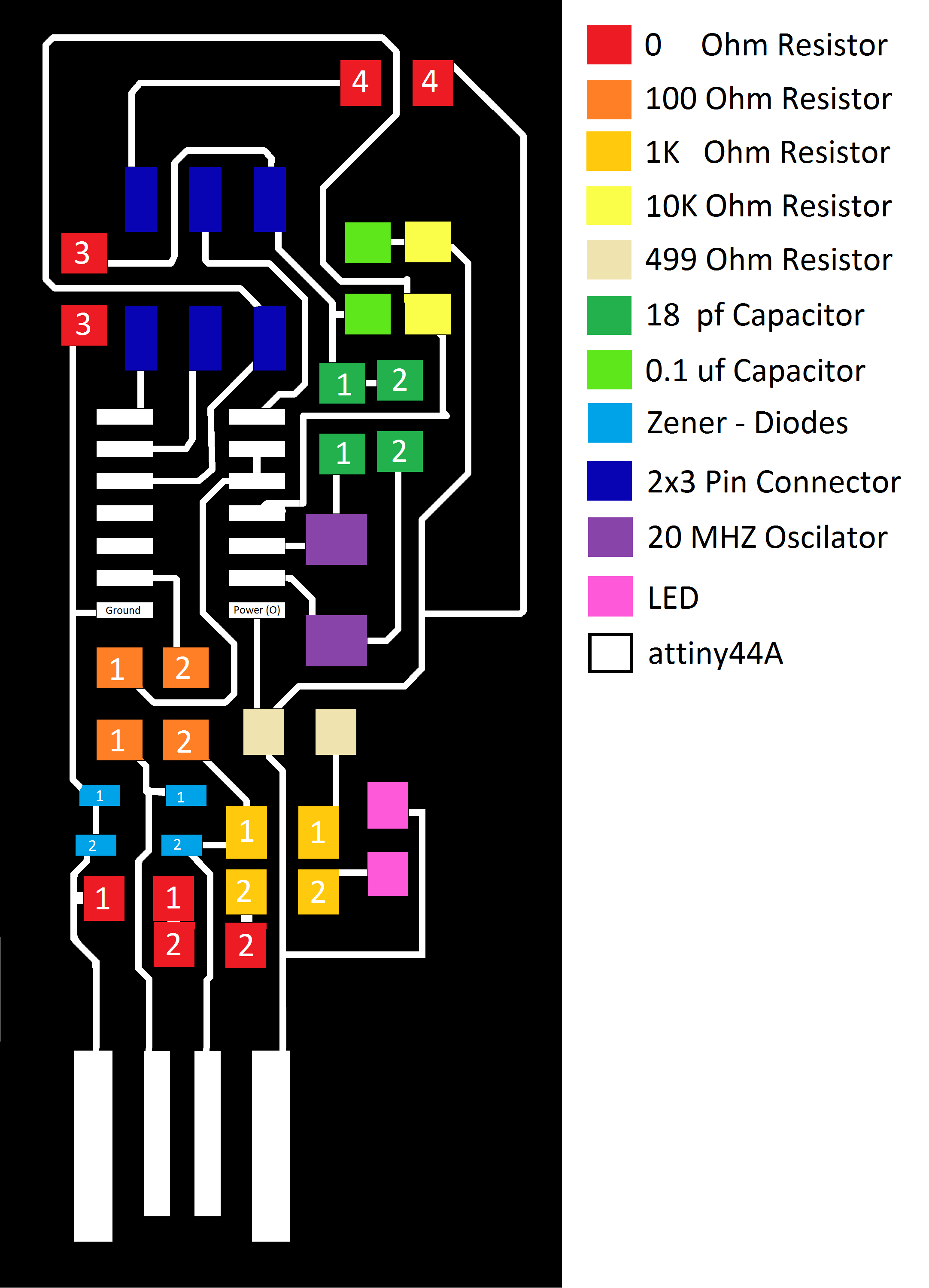
I am glad I straightened out the corners. Now the milling goes way faster (25 to 5 minutes)! For this second round of soldering I used the following order to prevent pieces getting in the way of each other:
- 2x3 Pin Connector
- attiny44A
- #3 0 Ohm Resistor
- #4 0 Ohm Resistor
- 0.1 uf Capacitor
- 10K Ohm Resistor
- #1 18 pf Capacitor
- #2 18 pf Capacitor
- #2 100 Ohm Resistor
- #1 100 Ohm Resistor
- 20 MHZ Oscilator
- 499 Ohm Resistor
- #1 Zener-Diode
- #2 Zener-Diode
- #1 0 Ohm Resistor
- #1 10K Ohm Resistor
- #2 10K Ohm Resistor
- #2 0 Ohm Resistor
- LED
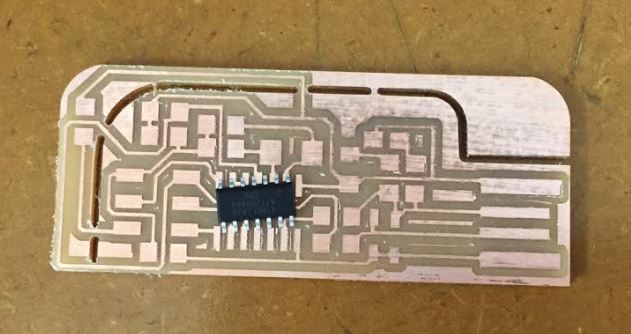
Also we didn't have any 18 pf Capacitors so I used a 10 pf Capacitor in it's place. Soldering went well this time around and everything was in place. I did make one error. LED stands for light emitting diode so make sure the LED is oriented the correct way or it won't light up.

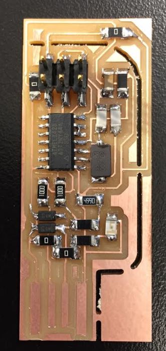
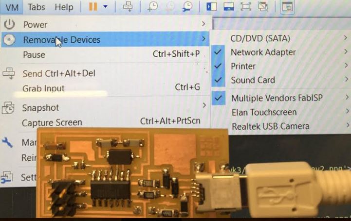
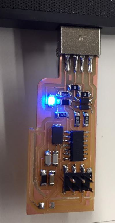
One note is if you snap off the first half of the snap off (before it passes through any traces) you can plug the board right into a USB socket to provide power during programming. I also found that even after adding big blobs of solder and some vinyl behind the plug in usb it was still a bit loose and finiky so I went and soldered on a USB male header. After that, it plugged it and worked great! See final pic below with light on! I went and it programmed no problem once I added the USB male connector to ensure clean contact. However, it won't program other boards. I have been debugging it for a couple of hours and can't figure out what went wrong. :(.
So just to be safe I went a put together the basic design and man did all of my learning make this go so so so much faster. In under an hour I had milled and stuffed the whole board and it programmed no problems and then after removing the solder blobs it is recongnized by my computer! Success! It works! When I get some time I am going to have to go back and figure out what was wrong on the other board. Or add some lights to the basic board! Again I should have started with a more simple thing --- maybe I'll learn sometime before this class ends lol.