Input Devices aka Knock Knock Who's There
For this week our task was to make a new board with an input device and program the board to work with that device. I decided to use the piezo as an input and try to measure knocks. I am considering having a secret knock activate my final project because that would be fun so wanted to start working with that now. I also put on two buttons which I want to debounce as well as that would be the other approach to activating my final project. Finally I put on a couple of LEDs so I could test the logic in the state-machine I will most likely end up having internally with the LEDs displaying the current state.
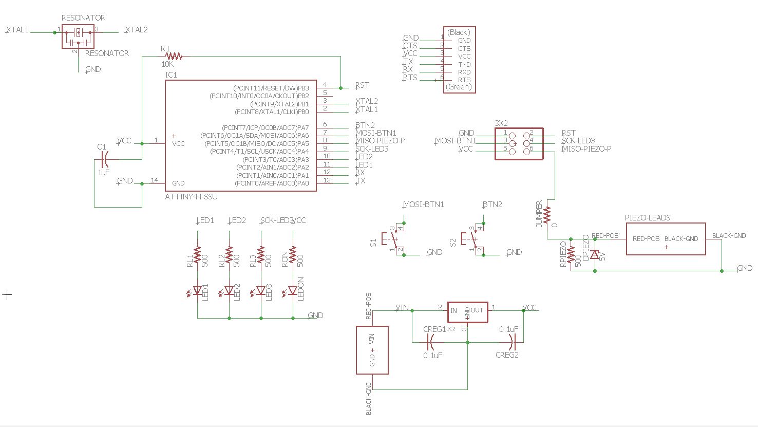
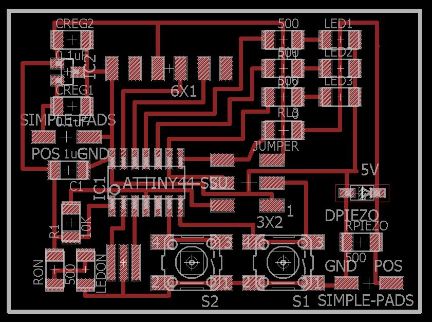
I first went online to figure out how to attach a piezo to a circuit and found this great set of lecture slides from the University of Utah. So then it was time to design a circuit again in eagle. I started with my old board as a base and added in the extra components. I also decided to add on a 5v regulator and maybe try powering it from AAs (as I will probably do that in my final project). I also made my own component which was simply two pads for both the piezo attachment and the external power attachment. I followed another sparkfun tutorial to figure out how to do it! And again, the tutorial was super usefull as the steps weren't very straightforward without it. Here is my final schematic and board. Then it was time to mill it. Pictures below:

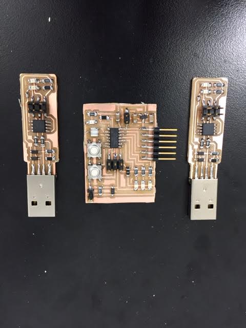
Of course per usual the mill decided to not cut all the way through on the outline cut so had to go at it with the exact knife. I also decided to mill out two of the Brian model programmers so that I could stuff those as well and hopefully get a working programmer (as mine is currently not working). And again even when setting the cut depth deeper it didn't make it through. My traces are all perfect though... I must be really not zeroing the larger bit for the outline well. Oh well. The exacto works fine. I then stuffed the boards and plugged them in and the power lights turn on so that's a good sign. Time to program them all!

First it was time to program the programers. Make sure you read the instructions carefully!!! I didn't and missed the make fuses command on Brian's instruction page and spent hours trying to debug. Once I ran it with make fuses, WHAT HAPPEND
So now it was on the programming the board I started with a very simple file to just have each button tied to a LED and the piezo tied to an LED as well. This was designed to just test the various parts of my circuit to make sure it works. I also then wanted to make sure that the regulator would work as well from this very simple code! That simple file can be found here with makefile here.
Well it turns out trying to jump ahead can bite you! Somehow despire my best googling my design for the regulator is not working correctly and it got SUPER hot and caused the board to malfunciton. Removing it from the board and letting the board cool down solved my problem. It programmed and the simple test demo works! The buttons press and the lights go on. But the piezo isn't registering. I will have to debug that. In the meantime I tried to debounce the button inputs. I don't really understand how interrupts work with AVR coding so decided to try to just make a simple counter to make sure that for a given amount of time the result is for the most part a press or not a press. This was a very frustrating experience. I had a really hard time getting this to work on the AVR despite being able to do it on FPGAs in the past. Turns out going and looking at my old code was super duper helpful! Got debounce up and running on the buttons! I can do binary counting on the 3 LEDs up to 7! The code for that can be found here. To make it simply change the target in the previous makefile by adding the .debounce!
Also an important sidenote. It turns out that programming an AVR from a VM doesn't work very well at all. However, the wonderful tutorial for installing the software to do so on Windows was provided here and was super helpful! Also the commands to end up making your files are: 1) make -f name_of_makefile 2) make -f name_of_makefile program-usbtiny-fuses 3) make -f name_of_makefile program-usbtiny. Also if you think it isn't remaking the files correctly after you change them then clean out the directory before remaking with: make -f name_of_makefile clean.
Back to the piezo! Using the oscilliscope I was able to determine that my problem was that the signla was too low (never broke 1v) and that's why it wasn't recording it ever as a high signal. Therefore, I decided to try to go straight to implimenting ADC and then looking at the various small values coming out of the ADC. I went and updated my code which you can find here. Unfortunately, once I got the ADC code compiled I went to upload my code and then out of nowhere my board stopped programming! :-(. I can't figure out what is wrong with it and unfortuantely, I don't have time to mill and stuff a new board so I guess I am stuck ending here this week. Regardless I did get the debounce working and honestly, I don't think I will end up using the secret knock anymore on the final project anyway (after thinking about it a bit). So really I'm pretty happy with the end result. Also since the only response I need can be triggered by connecting a circuit I can just use the approach the shopbots use and simply have a plate waiting to be touched. This would complete a circuit and could be between a pin and GND and then would work like a button so again the debounce I did this week is going to be all I need.
UPDATE: After thinking about it a while I figured out what went wrong. In debugging the board I realized I removed the diode at one point which allowed the piezo to fry the pin it was connected to. This wouldn't be such a big deal except it was connected to the MISO pin so now I can't reprogram the board unless I get a new Attiny. Since I am writing this as I walk into class this will have to happen another week.
UPDATE 2: Since I won't be using Piezo in my final project I never finished this but I did use a Pyro sensor on my final project so see there for more input usage!
Back