Brian builds a home alarm controlpad
Click for Video!
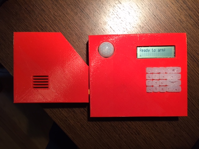
In my final project I designed a home alarm keypad. The keypad takes in button inputs for a code and arms. Once it is armed it waits to be triggered by motion from the Pyro sensor and then counts down and sets off the alarm. During the countdown or once the alarm is going off the user can input the correct code and it will disarm. I designed this keypad in the hopes of extending it into something useful for my home so I added in a couple of extra buttons and room for additional periferals so that it could ideally eventually communicate with wireless door sensors and send my text notifications of events over the internet. I 3D printed the enclosure and made silicon buttons from a mold. My electronics were a sereies of networked boards. All of the various components can be explored in much more detail in the following secionts, but I will first describe the process at a high level.
In terms of what has been done before, as far as I know no one has done a home alarm system keypad. However, there have been a variety of alarm clocks produced, and one past HTMer even made a beautiful multilevel molded keypad. In most of those projects a lot of work went into a beautifully designed enclosure. For me, the electronis and functionality were more important and the enclosure simply needed to hold everything in place and allow for the buttons to work. Therefore my enclosure design was much more complicated on the inside than outside. However, I did end up still spending a lot of time on it.
My bill of materials and cost is as follows:
In the end I found that I can 100% produce such a device. However, I need to significantly reduce the size of my various components and leverage more timers and interrupts ideally on a higher pin count device such as an XMega so that I can reduce the footprint into something small enough to be used practically. I also would like to avoid 3D printing for the enclosure if possible in the future as it is such a time consuming processs. Since my enclosure really needs to simply hold everything in place I was thinking that I could simply lazer cut some layers of acrylic to form the same kind of final result after gluing the layers together or have an acrylic faceplate on top of a simple wood box. That said, I actually don't think it would be that hard to redesign and add on the additional components I want to add on in order to produce something I could actually use so I am very happy with everything I learned this semesters. I also learned that if I ever do have to 3D print things again I will always go to the 3DWox first. It was so reliable and everything else wasn't! I also still want to build that table I was hoping to build someday!
Initial Ideas and Concepts
Initial Concept
In week 1 I learned CAD for the first time and came up with the basic design of the table that I want to build (sans electrical-mechanical components). Commentary on that experience can be found here.
However, while I do really really want to build that table at some point I figured out in the make something big week that I really don't have the time to do all the woodworking I want to do this semester, especially not a large table. It is now output devices week and I still haven't finished the woodworking for the make something big week. It is time for a different final project.
Concept v2
To that end I am going to make a home alarm keypad. I want it to be able to have a bunch of buttons for input, an LCD for output, as well as a speaker to sound the alarm. Ideally I would also network it to some other sensor that was a door sensor and maybe a motion sensor in the keypad itself. All of this would be housed in a 3D printed housing and would have molded buttons for the keypad. In the extreme it would network over wifi to a home server and email me status updates (but that I think is more of a longer term project). This would cover most of the weeks of this class so I think it will be a comprehensive project!
As I have been learning these past few weeks it is very hard to get one Attiny to do a ton of different things without mastering interrupts and timers and all of the other hidden but powerful AVR things. Also, given that I will need a LOT of pins and networking AVRs is a plus in the class I think I will break my project down into subsytems each with their own Attiny networked over serial with the LCD board as the main state machine. On the LCD board, an Attiny44 after all of the LCD pins and clock pins I am left with 3 pins of which two will be used for RX/TX serial and the last one will be a direct link to the speaker. The speaker will be an Attiny45 with one pin to the speaker and one to the main control board as an activation signal. There will be two Attiny44s that cover all of the button inputs and will have 2 pins for RX/TX and the rest connected to various buttons. There will also be a board for off chip networking that will be used to do RF/Wifi/etc. to connect to computers and additional sensors as well as ideally one motion sensor to have on the board itself. Given that each board has dedicated tasks it should be much easier to code each board as there aren't competing interrupts and timers. Also over serial I can send various characters to mean various things.
As for the overall aesthetic I think I will keep it quite simple. Probably just a standard rectangular keypad like on a telephone and an enter and backspace button. The rectangle will also need slits for a power and armed LED and a slits over the speaker and a space for the keypad and the LCD. I also may want to think about housing the speaker in a way that makes it louder. This will probably require a two part 3D print so I can print the faceplate to slot into the back and put the circuit board, LCD etc. in the middle. I also will need a compartment for the battery and a way to change it. I think I will just go with simple 9V power. If I have time I should probably put together a power level detector to start to notify if the power is getting too low and the battery needs to be replaced.
As for progress as of week 11 I showed that I can output to a speaker and to an LCD. In week 9 I learned to debounce button inputs. I am hoping to figure out the TX/RX comms between boards in week 13 and hopefully the Wifi/RF as well (TBD). And I feel confident that at this point I can quickly CAD design what I need for the 3D printing and for the molding and casting. So if by week 13 I have all of the electronics figured out then it will simply be making the final board and testing that which shouldn't take very long and then simply CAD designing the housing and molding and casting the buttons. Again I think this is very doable in the last week or two before it is due as long as I know how to do all of the subparts. Week 13 is going to be critical for me! In the meantime I will continue to think about the overall CAD design and work on making sure all of my input and output devices and code are desiged and ready to go!.
Thanksgiving Update / Final Concept
Well it turned out that there were a TON of complications with the multi-input Tx/Rx line BUT I found a solution by using another attiny as a data bus. So I am going to go with that approach. I feel like I have all of the foundation behind my electronics done, I now have to start pumping out boards and building the enclosures. I also think I am going to punt on the wifi to another board that is a door alarm for now as I just don't think I'll have time. That said, with my databus approach I can easily leave a pin to connect to another attiny that is doing that connection which can be added at a later date! So if I have time my project should be modular enough in its design to incorporate such features. You can see my data bus design as I figured it out in week 12 and week 13. I also have the foundation to connect to a node.JS interface to email myself notifications etc. but again I'm going to leave that as a stretch goal for now! So my final set of steps to get this done are:
- Update my design, mill, stuff, and program a button board for all of the buttons.
- Update my design, mill, stuff, a power board
- Update my design, mill, stuff, and program a serial bus board.
- Update my design, mill, stuff, and program a main controller board.
- Update my design, mill, stuff, and program an LCD board.
- Update my design, mill, stuff, and program a speaker board.
- Integrate the boards.
- CAD, mold, and cast buttons.
- CAD and 3D print an enclosure.
It is going to be a race to the finish but I have hope that since I know how to do everything and it is just execution I can get it all done!
Progress and Final Design
I have gone ahead and designed the boards that I am going to use in my final project. I decided to reduce the amount of boards from my final concept down to fewer integrated boards. My final list of boards, their status and design follow. In general if you haven't been following along from week 1, I decided to use Eagle for all of my board designs. I strongly suggest look at the SparkFun tutorials on Eagle to get started if you haven't used the software before as they step by step explain how to use eagle well: schematic engine and board layout engine. I also exclusively used the Roland Mill which I have fallen in love with. I find operating it very easy at this point. Once you get the handle of zeroing the bits and replacing them it is mostly plug and play given that the fab modules do all of the calculations for you. For more comments on my learning electronics production basics look at Week 3 and Week 5. For more comments on my learning AVR coding look at the electronics weeks: Weeks 7, 9, 11, 12, and 13.
Button Board
This board was an extention of other button boards I made throughout the weeks so I assumed it would be relatively straight forward to make. To keep the board as simple as possible I made a couple of design decisions. First I decided to have it get passed in GND and VCC like in Neil's serial networking example and then send over TX1 and TX2 the buttons. The reason I used two TX lines and no RX lines is because the buttons don't need to know what else is going on and to keep things simple I connected the buttons between ground and a pin on an Attiny44 and thus I needed 16 free pins so used two Attinys. To further support my keep things simple mantra I decided to use two programming headers, two oscilators, two capactiors, etc. I am sure with a little bit more work I could have reduced many components through the use of switches and tightly coupling the two Attinys and would aim to do that if I did a v2. I also decided to include two vias for the TX1 and TX2 lines because it would have required many 0 ohm jumpers otherwise. In designing the two Attiny board I found that by using different names for power and ground for each Attiny makes things easier as they will most likely have to be connected with jumpers eventually anyway (and if they are the same if you re-name them it will still want you to connect them AND connect them through the jumper which is really annoying). Here is the scheme and board file and images can be found below:


I ran into an issue with fabmodels in that in Chrome it crashed and couldn't handle the size of the traces picture. This was very surprising to myself and to Neil. Despite the fact that I used an overly large DPI, the image size in absolute pixels should have been supported by fabmodels. That said, after a lot of confusion and attempted debugging, I switched to Firefox and was able to get fabmodules to produce a path! Not sure why Chrome has a memory issue where Firefox doesn't but it did.
Unfortunately, since I was having so much trouble getting fabmodules to produce a path, I didn't check it for errors before I milled it and therefore I had some. First, there are two shorts on the board. The first near the programmig pins for attiny2, and the second near the 0 ohm jumper near the programming pins for attiny1. Second there are two cut connections. The first, under one of the buttons doesn't matter as the button itself serves as the connection. The second needs to be bridge with a bit of wire and is the source of ground for attiny1 near its LED and needs to connect to top row of the nearby buttons. Second, the vias it cut were too big. However, I decided to just run two wires across the back of the board and using a copper rivet and the wire and LOTS of solder it easily all attached and kept a good connection even with too large of an initial whole. Therefore once all of those mistakes were fixed it worked with 5v power.
To check our code to see if it is working on its own I use the python-serial library from the command line with its built in miniterm. To do this you simply need to type: python -m serial.tools.miniterm [PORT] [BAUD] replacing PORT and BAUD with the appropriate port and baud rate. If you use Neil's put and get char the baud is 115200. On linux the port is usually /dev/ttyUSB0 if you have used a USB to FTDI adapter and on windows you can run 'wmic path Win32_SerialPort' to find the port (credit to the internet for that one). They are usually COM# where # is the number of your port. Mine happend to be COM7. If you pick the wrong port the miniterm will simply fail so you'll know you got it right if it doens't throw an error. To double check if you think you have the correct one, unplug the USB you will get an error that the port was forcibly closed. When checking my code for the button board it worked perfectly! Here is the final C code and here is a Makefile to use with it. To use the Makefile simply run 'make' and then 'make fuses' and then 'make program' first changing the project definition in the first line to the name of the C file (button_brd). This Makefile can be used in this way for the rest of the boards as well.
One quick note on the code is that I used the #if #else #endif to allow for one flag value to be switched and then the buttons are mapped to a different set of values. In this way I only had to change that one value and then I could program the other board.
Main Controller / LCD / Serial Bus Board
Building on my learnings from Button board in terms of two Attiny layouts this was pretty simple to design. This board has two Attinys because one, which I call the serial bus, takes in the serial (and non-serial) inputs from the various sensors and buttons, and outputs a single solitary serial command for the other board to use. The other board is the main controller which has the main state machine. It uses the serial commands to transition between states and outputs data for the LCD to display and notifies the alarm if it needs to sound. This board had no issues in fabmodules and milled great (it was much smaller and simpler). Also because I took the time to check the path originally I had no shorts on the milled design and it powered up correctly the first time it was stuffed (power LEDs are super helpful in debugging). Here is the scheme and board file and images can be found below:

I first decided to program my serial bus building on my experiences and learning in Week 13. Given all of my learning there I assumed it would work immediately, but it didn't. I quickly realized that the error was that since I had no periferals board plugged in the input pin there was always low and thus always signaling a new serial input throwing things off and producing ugly output becuase ASCII 0 is a special character. I determined this because I plugged the board into the computer and used the serial monitor again and for the RX pin touched the output line wire wiht a wire attached to the RX input and saw tons of invaild outputs happening thousands of times a secocnd (quick side note: this really helped me understand why security researchers say that if an attacker has access to your hardware he can ready anything you do because it really is as simple as touching a wire tip to a data line and one can see everything that goes over it!). I decided to build a header that ties the peripheral input to VCC to keep it high. I also commented out the check for periferal input for now to keep it even simpler and more consistent. With that fix in place I was getting all of the right button values passed through the serial bus to the main controller! My final serial bus code can be foud here.
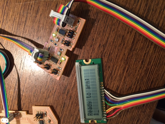
Then building on my code in previous weeks I though it would simply and easily start logging the code the user inputs and displaying them to the LCD as I did during output devices week. However, I got some weird math errors on big numbers which turned out was a weird casting error in my math. With that fix in place I was still stuck at 4 digits becuase of the size of uint16_t, the default int size. By moving instead to uint32_t, I could handle up to 9 arbitary numerical characters which I think is sufficient for a code. This worked perfectly. While I left it there in theory I could also use a char array to get the full 16 letter strings that the LCD display could support (although this would come with overhead on string compare instead of int compare on the final codes). A picture of an input making to the LCD from the buttons is below:
With the basics inplace I designed a state machine to handle the various states of the system. I remapped my buttons to special values to allow me to move my state machine around to any state for resting purposes and it all worked great (and then I moved them back to the values they should be). I even figured out how to use timers which had always confused me by using the this tutorial (which I then leveraged again in my alarm board). I needed to use these times to allow for asynchronous input from the user via the buttons and synchronous countdown when the alarm was triggered. One other thing I noticed in testing is that I needed to update my LCD as few times as possible as the blocking update of the LCD screen would clobber new serial inputs that occured during an update (as a side note this also reduces computations and thus saves power). So by moving the re-draw into only a need to do basis I had the whole state machine with buttons and timers working! :)!
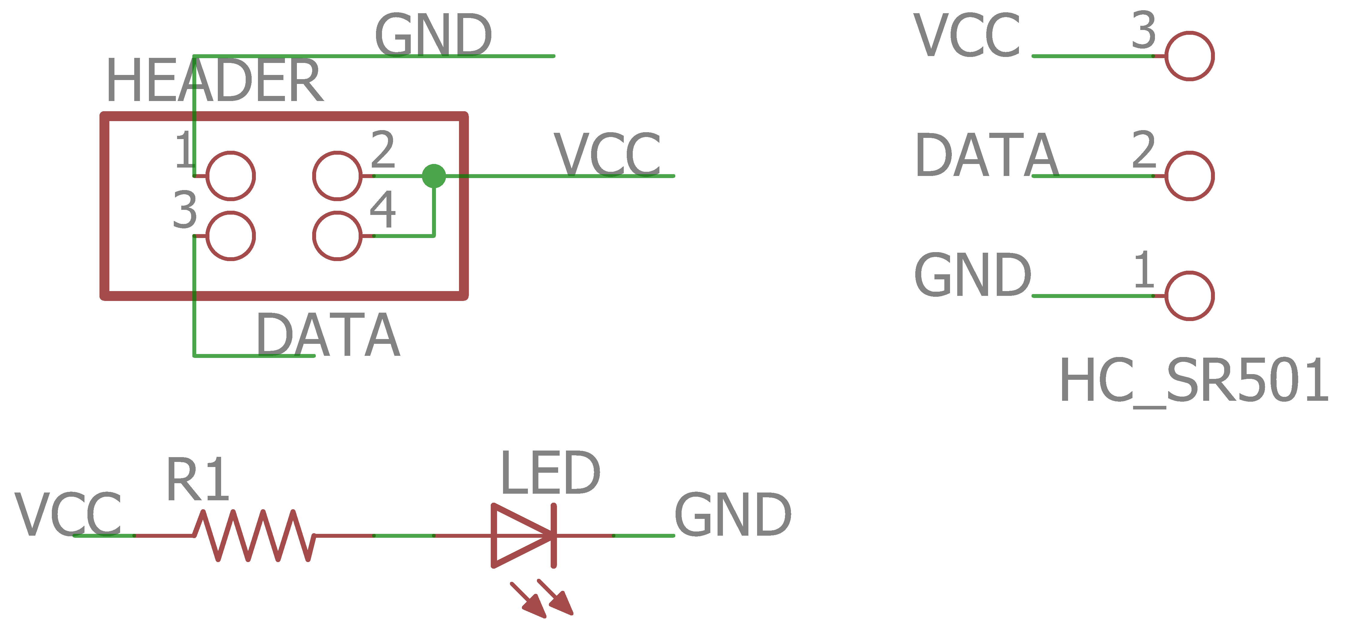
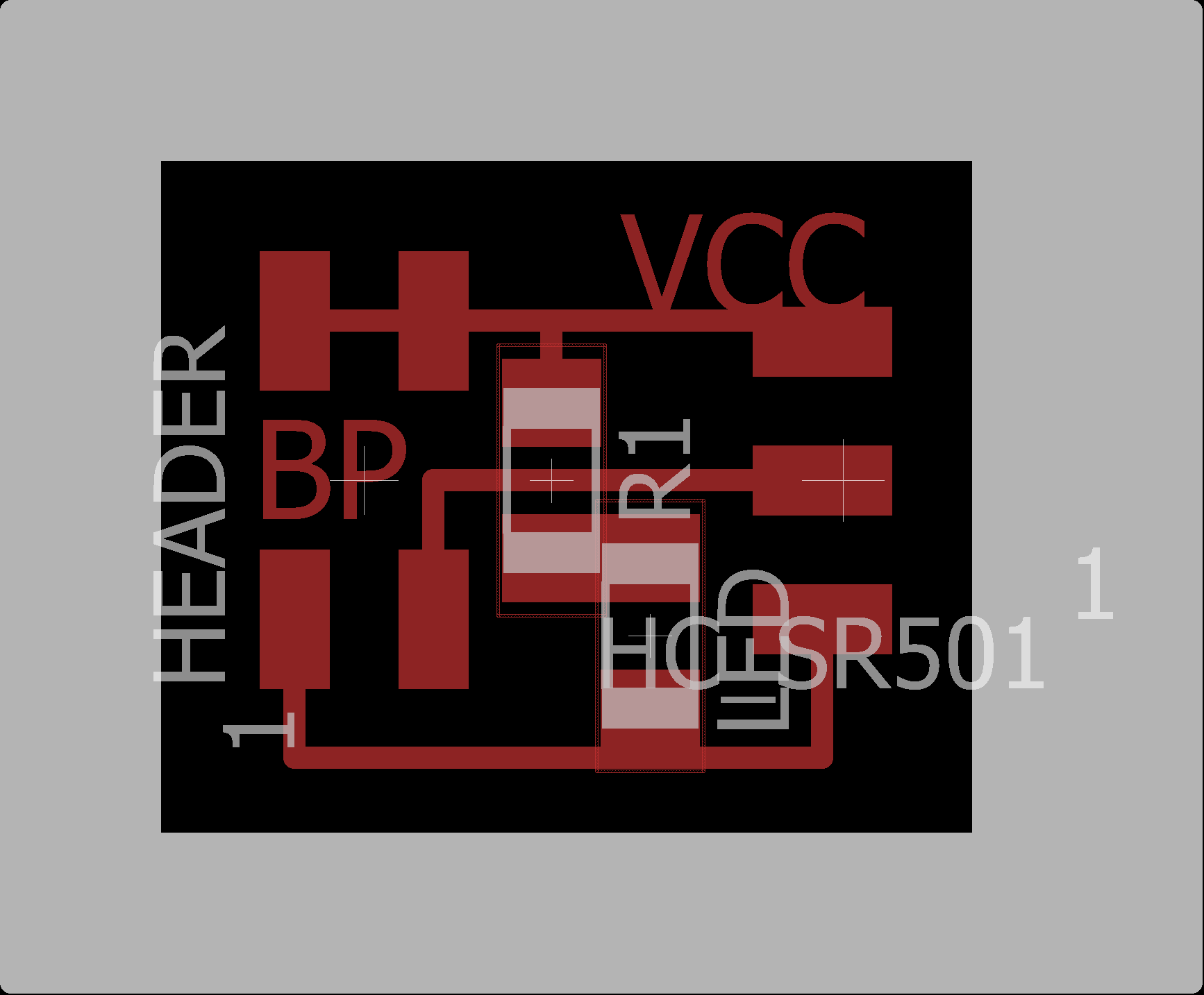
In order to simplify the connection to the pyro sensor and to make sure I plug it in correctly during testing I decided to make a small pyro breakout board with one led and a 2x2 header which I could solder directly onto the bottom of a pyro sensor. This was super easy and quick to do and milled in no time given its time size. Here is the scheme and board file and images can be found below:


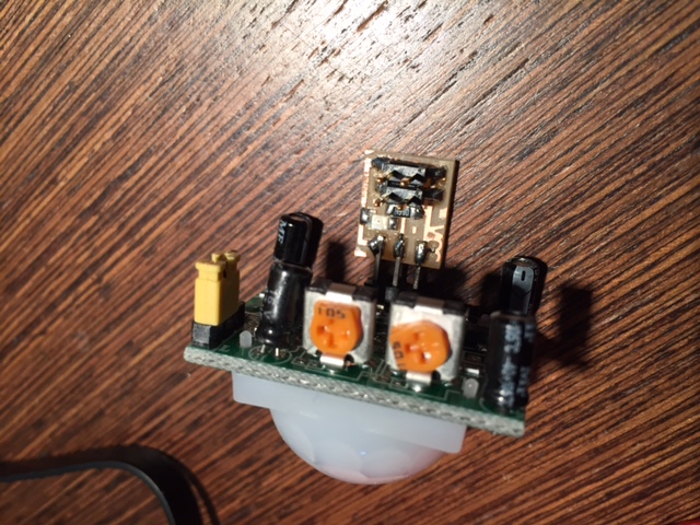
In my initial testing I was never getting any values back from the pyro sensor which was bizare to me. I therefor milled a second breakout board and attached female header pins instead of soldering it directly on to check and see if I just had a broken pyro sensor. The second one worked so my assumption was that my first pyro sensor was defective. Therefore I desoldered it so I could solder the working one directly onto the breakout (because my enclosure didn't have space for the female header pins and then noticed a short on the breakout from rouge solder. Fixing that rouge bit of solder fixed it and the original sensor worked just fine. One weird final note on the pyro sensor is that while they often work well, they sometimes seem to time out for a while so in practice with everything integrated I kind of need to move a lot and flick the sensor to get it to go off. That said, it does always eventually go off and then my serial bus board reads the signal and sends the alarm command!
I then tested with a multimeter the alaram signal output which went high on alarm time and was low otherwise so I called the main board fully functional and working! Here is my final main controller c code.
For now I am leaving the periferals board as an extension if I have extra time. I really at some point want to add networking to two door sensors so I can monitor both doors and not just rely on the motion sensor in the keypad. This will all need to be networked through bluetooth, RF, or wifi. Therefore, I left space for the peripheral input for this communication. I envision another board that does the long range comunication and sends the update over serial. I also am just realizing that if I want to add a second controller board at the other door I will need to update my board to allow for serial out from the main controller to the peripheral board as well. I leave this as a todo if I get to that even further extension step. That all said, since my serial bus can handle the multiple inputs it has now, once this board is working it will be simply a plug and play operation and it should all be fully functional!
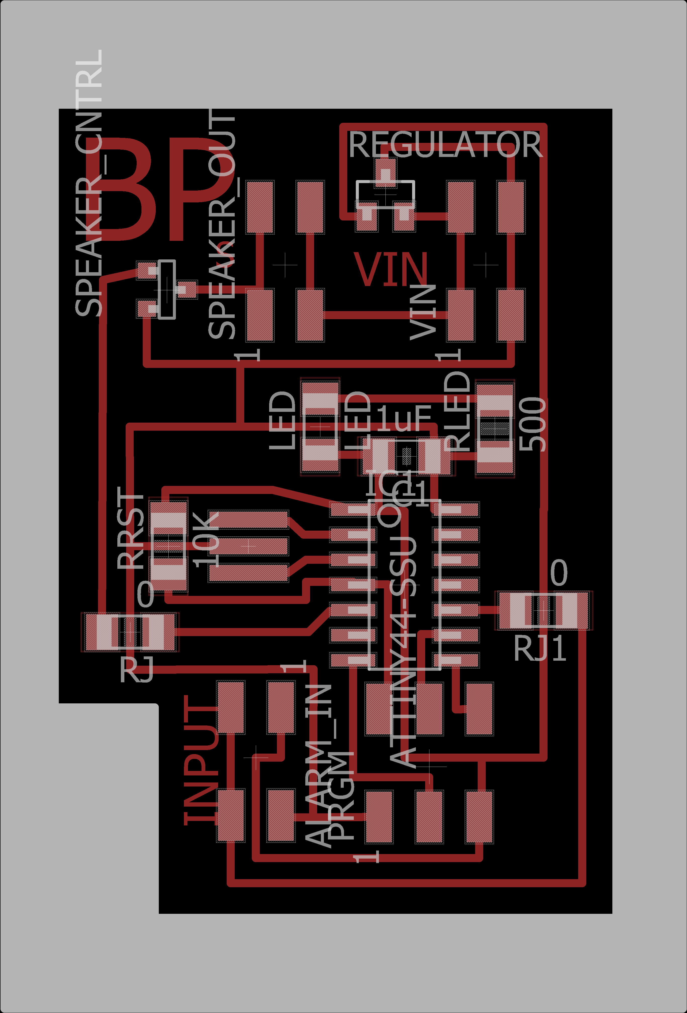
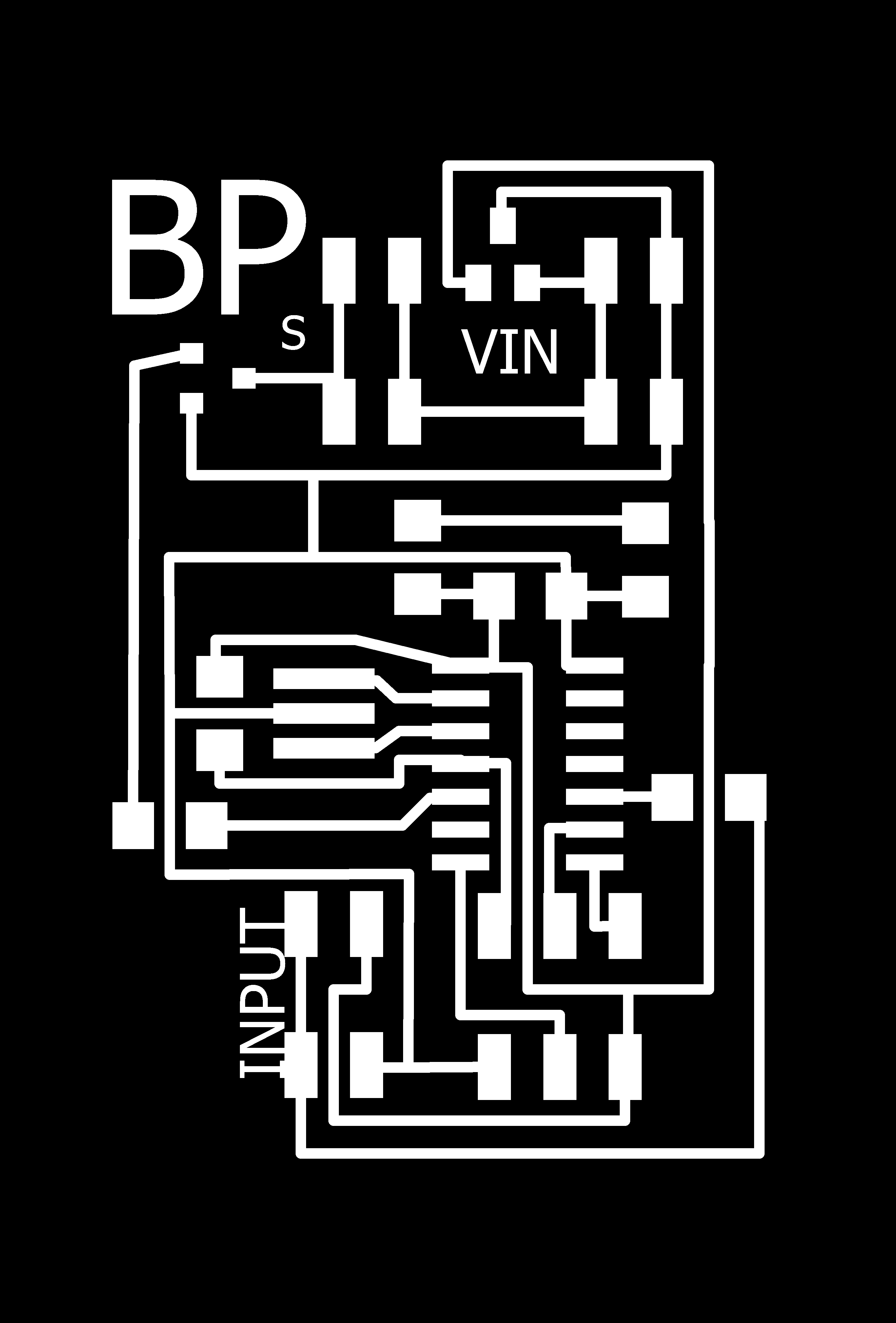
Speaker / Power Board
I decided to house the speaker with the main power in to have unregulated power going through speaker to make it louder. In my first design I used a mosfet like the speaker hello world but after talking with Rob decided to use an hbridge instead of a mosfet to allow for a high amount of current to flow through it and make it really loud since it is an alarm. My initial design is therefore a mashup of the hello worlds for the speaker and the motor driver. Therefore I started by milling what I called version 2. One thing to keep in mind with the H-Bridge is that it says in the spec sheet it needs to be conneted to a large ground plane on the bottom to help dissipate heat. Here is the scheme and board file and images can be found below:

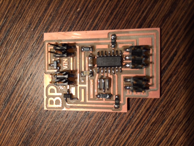
After milling and stuffing it wouldn't program so I went about checking for shorts and found one on the zero ohm resistor closest to the H-Bridge. That said it still wouldn't program. Weirdly if I removed the regulator it would program. This means something weird is going on. So I went ahead and quickly milled the original mosfet design since I had gotten that to work before during output devices week. Here is the original verison scheme and board files and the images are below:

This time it prorgammed just fine, however, it didn't work. I did some digging and realized that the attiny45 only does 8 bit timers, not the 16 bits I had been intending to use from my code that worked ont he attiny44! However, with a 256 prescalar to make a 520hz signal I only need to count to 75 so it will still work with an 8 but timer. Therefore I updated the timer code based on the datasheet to work with the attiny45. That said, it still wasn't working and the output signal on an oscilliscope seemed to just produce nothing. I was very confused, but since no one else was making boards in the shop and there were a lot of scrap pieces of board I could use for these small boards I decided to go ahead and mill version 3 with an attiny44 which I knew from my main controller board I knew how to use the timers on it. Here is version 3's scheme and board files and the images are below:


I had one issue in the milling in that when I inverted the outline it added additional cutting lines which didn't hurt my board but removed enough of the border that the tiny board I had did not have enough additional tape holding it down and it spun up into the air. By pausing the job and adding longer pieces of doubel sided tape after the unneccesary initial cut I was able to get it to stay down and mill out. I quickly programmed the board with the correct code for the attiny44 timers and it STILL DIDN'T WORK!
I then went through the code line by line and noticed that all along I had the pins labeled incorrectly -- *facepalm* -- and once I fixed that it worked perfectly. Given this silly mistake I assume that v2 for sure and maybe even v1 will work if programmed correctly which is why I still left all the files above if anyone wants to experiment. Here is my final c code and the Makefile from the other boards can be used here again.
Periferals Board
As mentioned in the main board sections this will be completed only if I have time which at the moment it does not look like I will. That said I intend to do it in the future and hopefully come back and update this page.
As mentioned before I went down the route of 3D printing the encolsure and molding/casting the buttons for the keypad which can be found below:
3D Printed Encolsure
I've been using Solidworks for my 3D printing since week 1. I found it very unintuitive at first but very easy after using it a bunch. If you end up using it have faith things get better! It is really really good for multipart things as you can design each as a part and then assemble it as an assembly. In general using equations and variables are your friends because it makes things parametric. For more comments on my learning CAD design and Soliworks look at Week 1 and any of the other non-electronics weeks.
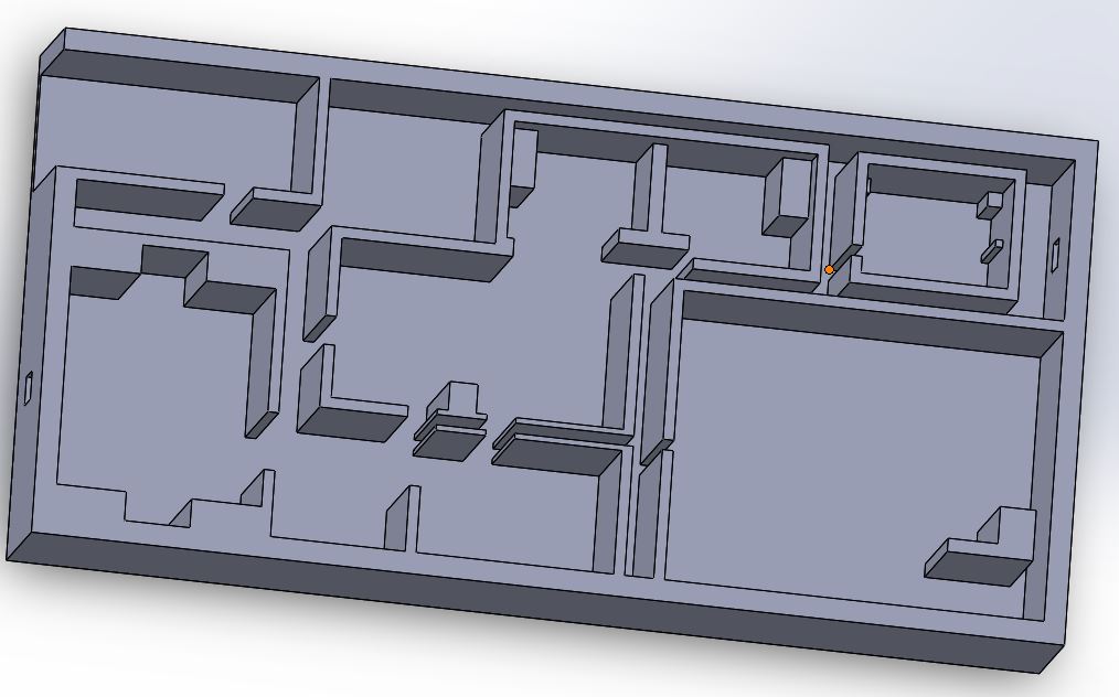
My initial design was one big box with little compartments for everything. It was pretty quick and easy to put together using parametric design principles. That said the final result is quite large as my various boards all take up a lot of space. If I went into production I would need to reduce the number of headers and stack boards and go full double sided etc. But, we have a Makerbot which can handle this large of a print so all good! My CAD design is shown below:
First I printed a tiny test print to see if the design made sense. Here I learned that I need to provide more tolerance between the top and the bottom so that the top slides over easier, but otherwise it looks great. Time to send the large print overnight! And the Makerbot failed :(. Not sure why but it stopped printing after it got through the first couple layers and to make matters worse after testing the Makerbot a bunch it seems to be broken. Later another classmate would take it apart and find tons of issues and put it back together and get one print to work but then it failed again with the same error. It seems like the Makerbot is out of commission. See below for a picture of my tiny test prints:

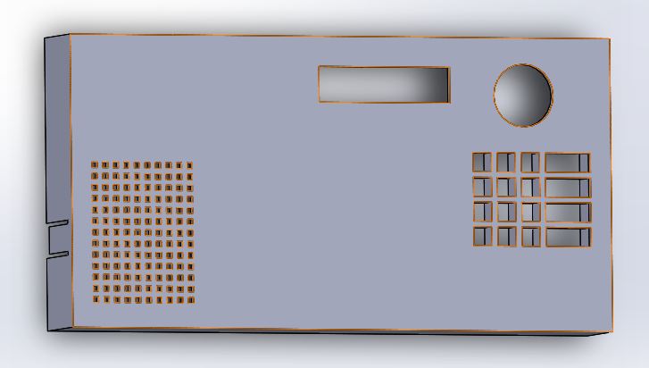
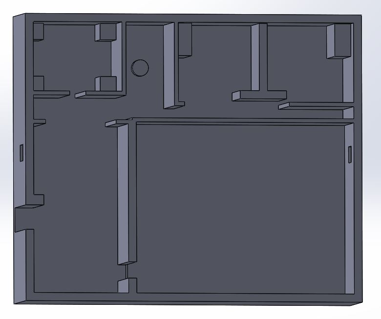
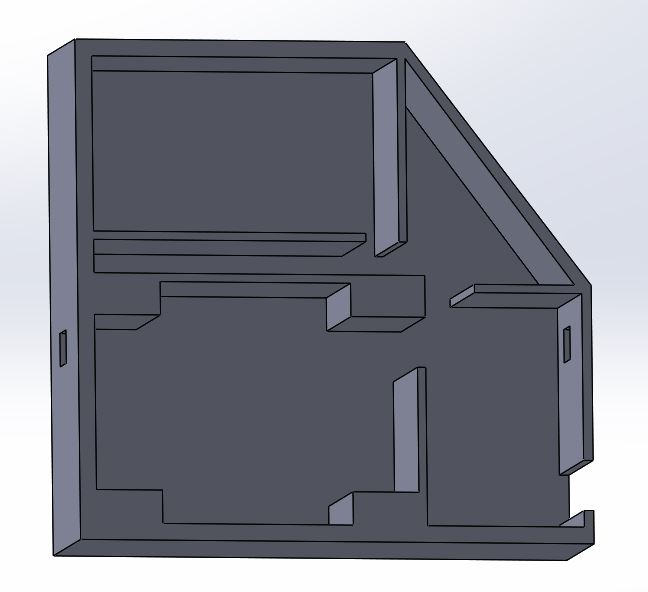
My new plan is to do a two part enclosure. One for the buttons, LCD, main controller, and pyro sensor, and another for the battery, speaker, and the regulator and alarm controller board. And then half way through designing the CADv2 Solidworks crashed -- insert frustrated noise here --- but after some more work I got it all designed. I made a couple of design decisions along the way. First I decided to move everythign closer tot he other walls to make the enclosures as small as possible. Second, I decided to use magnets instead of the tabs to connect things because it would be easier to remove and more fun (magnets are cool)! That said, when I sent it to the printer I screwed up again! I did not leave enough tolerance on the dimmensions of the inner spaces and none of my circuit boards fit in! Nooooooo! That said I printed on the 3DWox and it turned out great. That is one solid printer! So I went back to my designs and added in a LOT more wiggle room. Final CADv2 can be seen below:


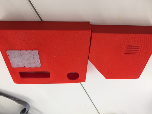
So I went and printed the smaller bottom on the 3D wox with more tolerance and it worked perfectly. In fact, I have a little too much tolerance and will have to tape or glue things down as they can wiggle about 1/8 of an inch! I then went and printed the top while I went to class. f course given my luck I missed a 1/2 inch in a dimmension on my top file and it was too small in that dimmension!!! NOOOOOOO --- so gonna have to reprint. However, since those prints take about 4 hours (Did I mention 3D printing is stupid slow and I will probably avoid it at all costs in the future) and the larger top and bottom take overnight I am going to print the larger top and bottom tonight on the 3DWox and the Ultimaker since no one is using either. Per usual the 3DWox worked perfectly, but the Ultimaker failed. The raft won't remove from the part so I can't get any of the buttons through or anything! Man 3D printing and me are just not getting along :/. So I reprinted again on the 3DWox first the other top part and then that larger top overnight and it all fits and all works! Finally I have two complete enclosures! Thank you 3DWox for being reliable and working! Also people be very very careful before you print and check your dimmensions and then ONLY use the 3DWox and life will be good! Some pictures of the various parts are below:


When attaching the magnets I glued them onto one side first with superglue and then let it sit for a couple of hours. Then I put the second magnet on the first and drew black Sharpie on the free side. By then closing the top if my calculations were correct there should be a small dot of black on the exact spot I want to put the other magnet. In both cases it worked perfectly! :) Then I just glued the black part down. This ensured I put the right polarity on each side of the glue and that it fit!
Finally I decided to print a small enclosure connector so a robber can't snip the power wire running in between the two halves. I made a simple design in Solidworks and then printed it in 20 minutes on the 3DWox. It worked perfectly per usual, I just forgot to account for the overhang from the tops and it was too short. I was heading out for the weekend so decided to just do it on Monday since it only takes 20 minutes. On Monday I came back and printed that final part out no problem! Now I have a finished assembly!

Mold and Cast Buttons
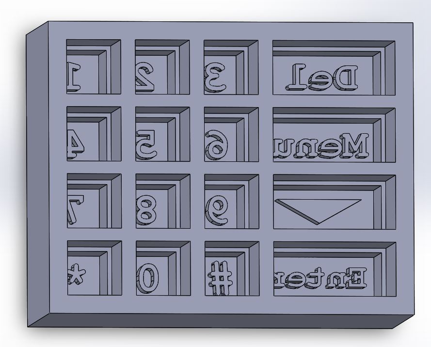
Again I am going to model in Solidworks (see enclosure). The trick is going to be that I want oomoo buttons (aka rubber) so I can't mill a positive then mold and then cast. Instead I need to mill a negative and then cast in there with the oomoo. This is going to be tricky beacuse I need tall buttons to reach to the bottom of the enclosure and need the fine details to be deep in the mold. Therefore, I can't use a small bit but need a small bit. So this providede a bit of a catch 22. To get around this I decided to first simply try to 3D print the mold in the 3DWox (since it was working so well for me see enclosure notes as well) and then if that didn't work print a support for the button board so it stays up taller and then mill out smaller button negatives. One important note is if you are making a negative you need to mirror the entire design so it comes out correct in the positive! My CAD and print are below:
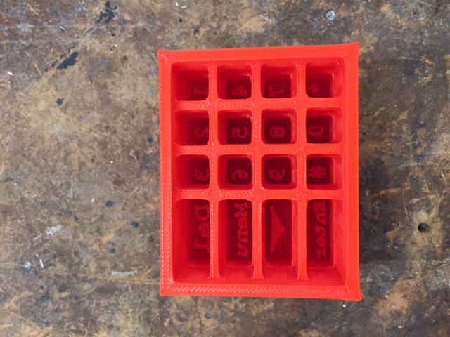
Then I sprayed in a ton of mold release and poured in some oomoo. Except after starting to mix I realized that I was making a rubber silicon mix and not an oomoo mix because it was clear. I didn't realize they both came in the same looking bottoles. That said, the silicon would work just as well for my purposes as oomoo so i just kept going. I just hope the mold release works so can do oomoo if this doesn't work and that the buttons are readible -- I was kind of looking forward to the blue. Unfortunately, I didnt' design the 3D print well for mold release and even with all of that mold release spray I can't get the buttons out. I even tried cutting out one of the button on its own and couldn't pry it out. I think I also damaged the mold trying. Then, right before I was going to break it, Rob came to the rescue with a hook shaped tool which allowed me to pull them out one by one! And they look great! In the future I would like to do it in a different color or add some colored insert into the button wholes because they are clear and hard to read but for now it is great! See final buttons out below and the hook tool:

Back