Week 5: Electronics Design
Introduction
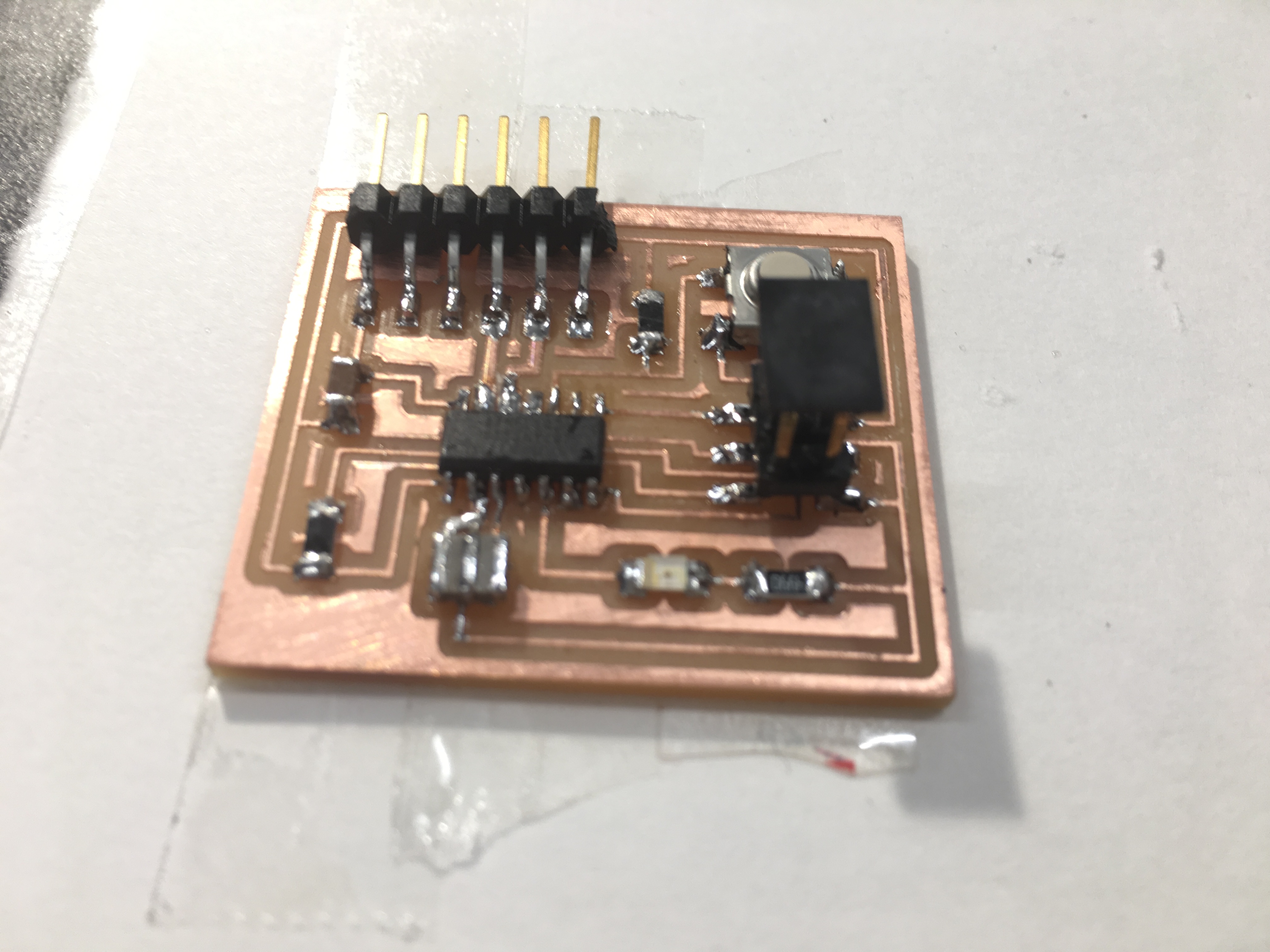
This week, I redrew the echo hello-world board (below) and added a button and LED (with current-limiting resistor). Then, I made the board using a similar process to the Electronics Production week. To design the board, I used the software EAGLE. (pic).
Phase 1: Design of the board
- Install EAGLE
- Import the Fab library in order to use the custom-made fab componenets. To do this, in EAGLE, go to File → Open → library and open up the Fab library
- Then create a new schematic (by going to File → New → Schematic)
- Now in the schematic, I imported all the different components. In EAGLE, there are two ways to do things: (1) use the icons on the sidebar (2) type in the command. Here, I will show you how to do both. To add a component you can type ‘add’ in the command line
-
A new window will be opened – go to the ‘fab’ library. Tip: Use the wildcard * when searching for the components, because the search feature is not so good. For example: *resistor*
Components I imported:- Resistor (RES-US1206FAB)
- Resonator
- LED (LEDFAB1206)
- FTDI-SMD-HEADER
- ATTINY 44 (ATTINY44-SSU)
- Cap (CAP-Unpolarized C1206FAB)
- Switch (6mm_switch6mm_switch)
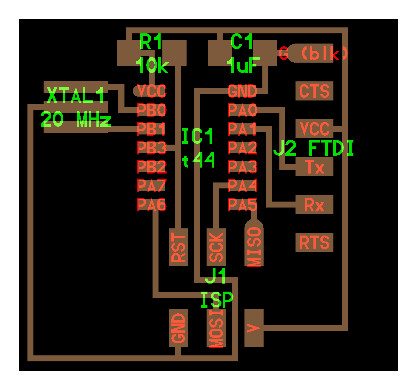
- Connect components – Use the ‘net’ feature to connect components together (pic). Tip: to move a component, you have to click on the ‘cross’ on the component
- Click on the ‘net’ icon and create a line with the green net from the ‘dot’ of the component to some arbitrary point
- Name the net by typing ‘name’ in the command line and clicking on the net you just created – enter a name relevant to that connection
- Then label the net by typing ‘label’ in the command line and clicking on the net – you should see a label appear
- Repeat steps 7 – 9 with all connections. Tip: To know if a net connected to a component, move the component around. If the net moves with the piece, then it is connected. If the net does not move with the piece then they are not connected
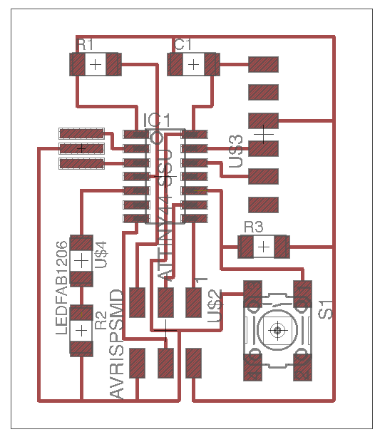
- To create a board, you can either type in ‘board’ in the command line or click on this icon (pic)
- When you generate a board, you should see all the components with the connections (if all the connections were done properly)
- To route the connections you can click on this icon (pic) or type ‘route’ in the command line
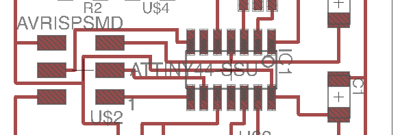
- To export just the top of the board type ‘display none top’ and you will get the following image. (type ‘display all’ to go back)
- Export the image – type ‘export image’
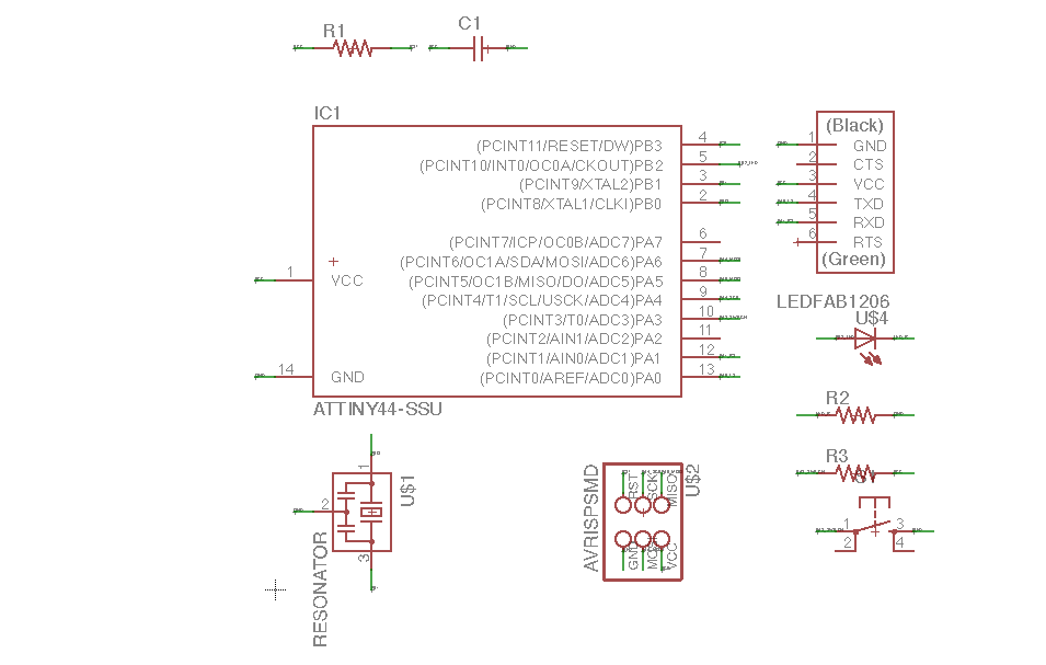
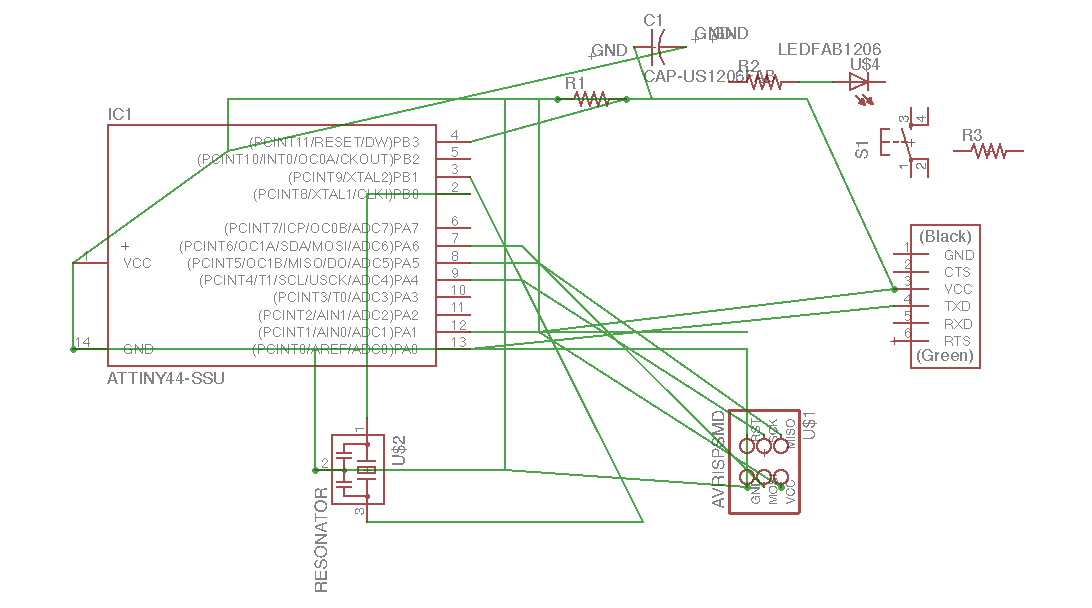
Create the schematic
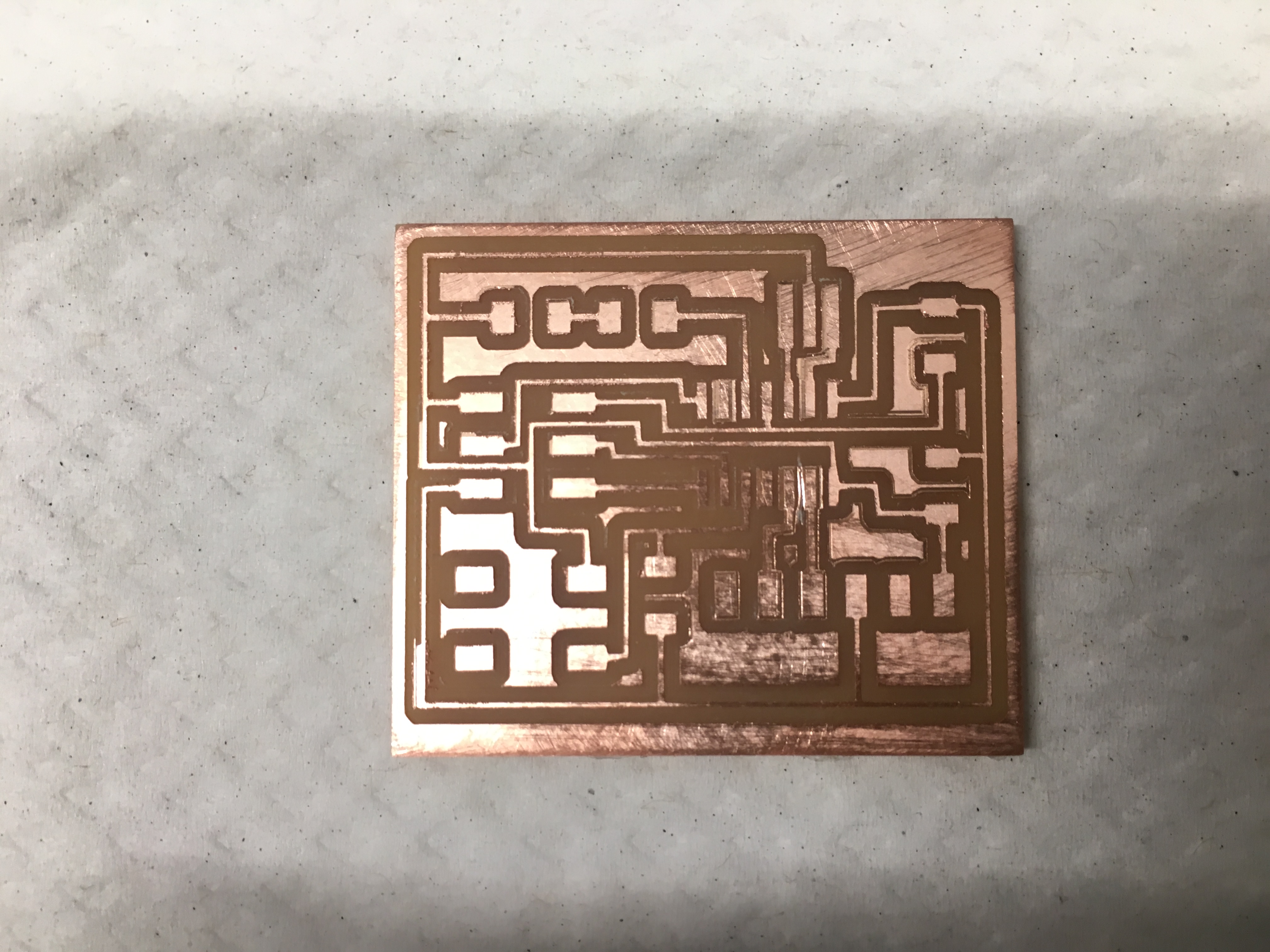
Create a board
Phase 2: Making the board
I used similar instructions to the Electronics Production Week" to make the board.
Challenges
-
I had a challenge with making the nets in the schematic.
Initially, I made the net connections by using the green lines to connect from one piece to another. It was a mess. Because many of the parts I thought were connected weren’t actually connected. All the green lines were intersecting and all over the place. It was hard to debug. Frustrated, I tried another approach.
First method which left a mess
Second method which worked well! - Another problem I ran into was that the software did not calculate a path for the board circuit outline. This was because the border outline created in Eagle was too far to the edge so the software wasn't even recognizing it. Instead, I created a border in Preview.
-
After the board was made, I noticed that the cutting didn't fully separate two parts as you can see in the picture. In order to separate them, I used a knife to cut away.
Before cutting away 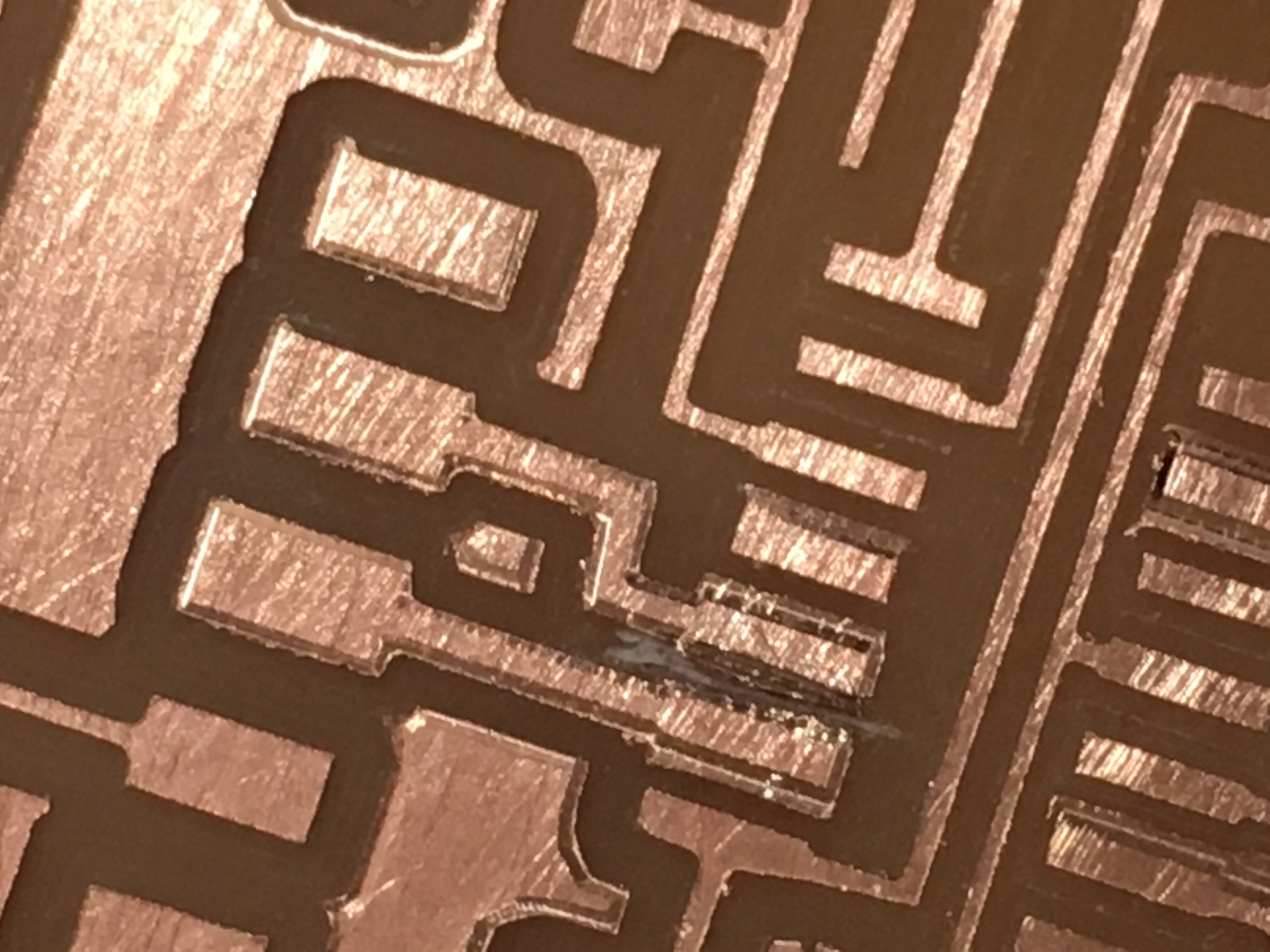
After cutting to remove