Making a Programmer
Choosing a design
This week I built two programmers (only one works) for the Atmel chip series. I began by looking at the designs available on the course site. I was drawn to the design by Valentin (http://fab.cba.mit.edu/classes/863.11/people/valentin.heun/2.htm) because of the breakaway piece from the PCB to remove the necessary connections instead of desoldering. I also liked the built in USB pads, I was worried that the mini USB connection for the other designs would be hard to solder and easy to break off. I ran into trouble with this one so I opted to make the classic ISP44 that others were having success with. Once that was complete I returned to finish the first one.
Milling
I began by downloading the trace and outline files from Valentin’s site. I set up the Roland mill to cut out the traces on the PCB. I used the 1/32 endmill and the standard fab module settings (below).
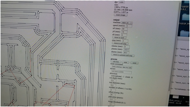
At first the mill wouldn’t run, luckily Rob was near by and came over to help me. He explained that I needed to load the Harvard settings into the fab module before running the java script in the terminal to make the link with the machine. He also explained how to use the view function on the machine together with the module to set the starting point of the cut. Once it was set up I sent the job to be cut.
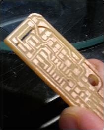
The results!
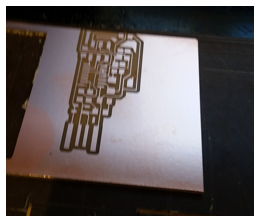
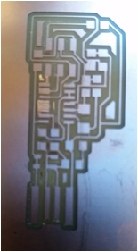
The traces came out nice and defined. But there is one problem with this board… I did not discover it until the next step. Can you tell what it is???
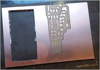
I changed the end mill to 1/16, loaded the files from Valentin’s site to cut the outline, prepared the fab module with the standard settings, and sent the job. The mill started up, moved to the top right corner of my piece and began cutting in the air… Brian who was helping me noticed it first and hit the view button the stop the cut.
The answer to the question above is that I did not allow for enough run in the Y axis for my job. If you look back at the pictures above you can see the traces continuing off the top of the piece. OOPS!
Also strange is that when the mill went to cut the outline it dragged the bit across the top of my piece, which was now trash anyway.
When I tried to reset the mill it was having trouble clearing the old job from its memory. I was told to hold down the two buttons that move the tool up and down at the same time to clear its memory.
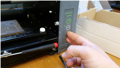
I tried this and then the green light started flashing and the machine froze. I power cycled it and reset the connection from the computer and then it started behaving normally again.
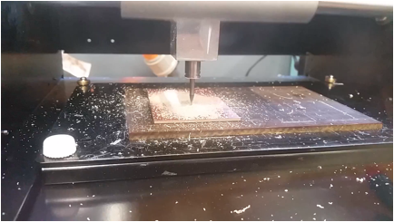
I took a new piece of stock and set it in the machine, this time with its longest dimension on the Y axis, to be safe. I went through the same processes mentioned about for the traces. I had been told by a lab mate to look for white dust on the surface to be sure the machine is cutting through the copper and into the substrate. I noticed this wasn’t happening and that it was only milling the surface of the copper. I am not sure why I changed the plunge depth in the setting to .15, same thing. Then I changed it to .2 and got the cutting results I wanted. Perhaps in my haste setting it up the second time I made a zeroing error? Below is a picture of the mill properly removing substrate and copper.
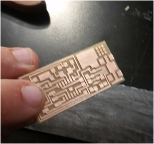
Here is the result from cutting the traces round 2:
Plenty of space in the Y Axis!
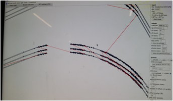
Next I started to cut the outline. I used the standard settings and hit send. It began cutting and calculated the job time at 30+ min. Others told me they had cut their parts out in under 5. I was curious why mine was so much longer. I noticed that the router was on a corner and moving very slowly so I zoomed in on that part of the tool path in the fab module and realized that it had calculated many many lines and changes in direction. I’m not sure if this is a constraint of the machine or just how the module decided to calculate the tool path.
While I was looking into this it started to make a very loud whistling sound. It seemed strange so I stopped the machine. Dixon came over and told me it sounded like the bit vibrating in the collet. He tightened it and the sound went away for a while. It seems like there is a fine line between to loose and finger tight like Neil recommended. Also the bit should be as far into the collet as possible and the work piece should be secured to minimize all vibrations.
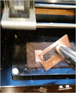
At first I thought it was neat that the extra material came up with the vacuum but then I realized it meant I had not secured it well enough…
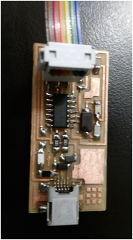
Here it is ready to be stuffed!
Stuffing the board:
I looked at the circuit diagram on Valentin website and made myself a “shopping list.”
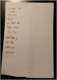
We didn’t have any 18 pf capacitors also at this point I had heard many other things about this design that started to make me think it was a bad idea. I had originally thought the thickness of the pcb was the standard thickness to fit in a USB port, it is not and would require some adjusting. It could ruin your USB port. No one in my section successfully programed it.
At this point I decided to make an ISP44 from the course website. This seemed to be the standard and other were having success, I figured once that was done I could go back to the other. Using what I had learned about milling from the first one I was able to prepare my new pcb very quickly.
I then made and populated a new “shopping list”
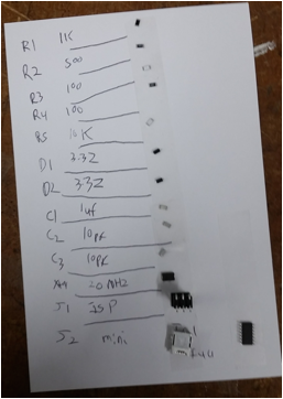
Notice how this one has both a label and name for each component. This makes it easier when referencing the circuit diagram.
I then soldered all the parts according to the diagram. I don’t have any pictures of me soldering because I was using both hands. Some things I learned are, if you find your hands in an awkward position try rotating the work piece 90 or 180 degrees. It is not as difficult to solder surface mount components, as it seems. For very small traces placed close together (like the micro USB) you can solder them all together then use the desoldering braid to clean up.
I was then able to program the board using the programmer that Rob made last year, and the software from the course site. I removed the solder jumpers and plugged it into my computer to check if it was recognized.
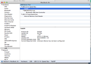
I almost didn’t believe that it worked on the first try!!!
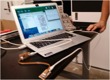
The final step was to use it to program something. Luckily Brian was finishing his board around the same time and I was able to use mine to program his.
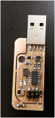
Here is a final photo of my board.
Once I had a working board I went back to try and finish the first one. I replaced the 18 pf capacitors with 10pf at Dixon’s recommendation. Here is the finished board.
Unfortunately I couldn’t get the computer to recognize it. One day in a world of infinite time I will return to finish it. Perhaps as I gain more knowledge about circuit design in this class I will be better able to trouble shoot it.
Things I learned / You should look out for!
· Make sure your local settings are loaded in your module.
· Make sure that you have enough room in all cutting directions, not just a good starting place.
· To reset the Roland Mill you can push the two buttons that move the tool up and down at the same time. When in doubt turn it off and back on again!
· Look for white (or other substrate color) dust while the machine is milling to be sure you are making it through the copper layer
· Check the tool paths for curves in your drawing to reduce time.
· Make sure the bit is screwed in tight enough, as far into the collet as possible, and that your work piece is secured to prevent vibrations, and loud noises.
· When arranging electronic components give them both labels and names.
· When soldering if you find your hands in an awkward position try rotating the work piece
· Don’t try and do small closely packed traces correct the first time, just clean them with desolder braid.
· Surface mount soldering is not as hard as it looks. Once you get into it can be very quick.