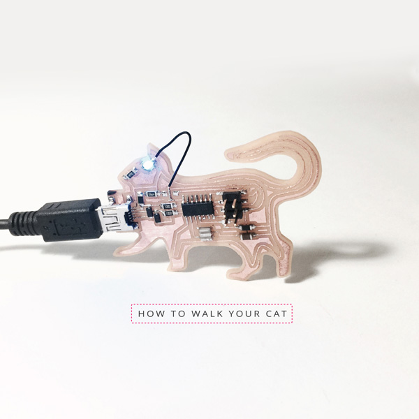
Electronics Production: HOW TO WALK YOUR CAT
Week 03 | How to Make (Almost) Anything | MIT Media Lab | Fall 2016
This week we were introduced basics of electronics production, with a task of making an in-circuit programmer to program programmers. After receiving introduction of using Modela to mill the circuit board, and surface mount soldering training, I decided to customize my FabISP into a cat shape to have some more fun.
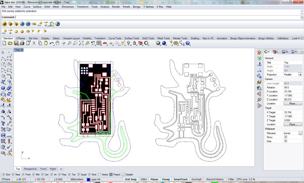
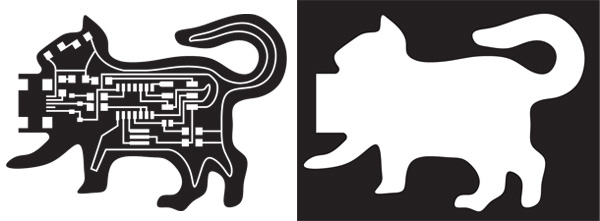
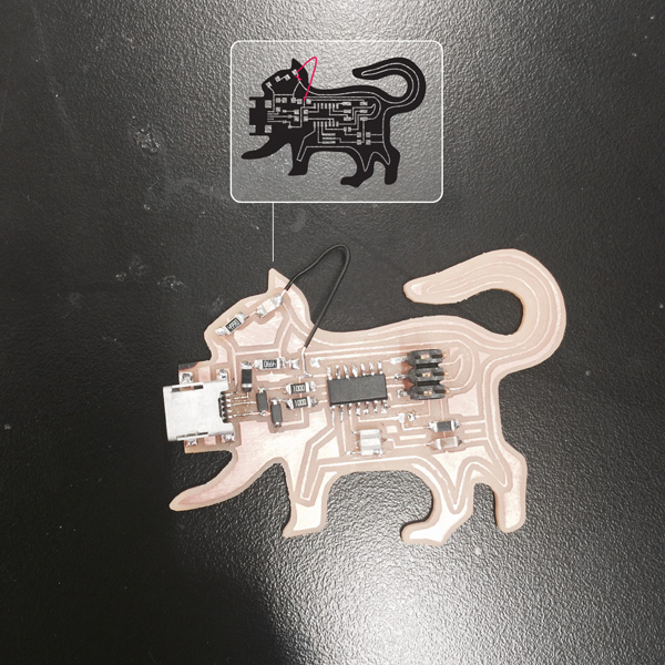
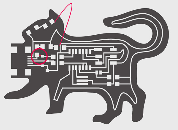
I simply picked (hello.ISP.44.res.) board to work with. I measured in illustrator the size of the board from the "trace" image file, and scaled the image into that size in rhino to make sure my trace of the solder spots are in the right location.
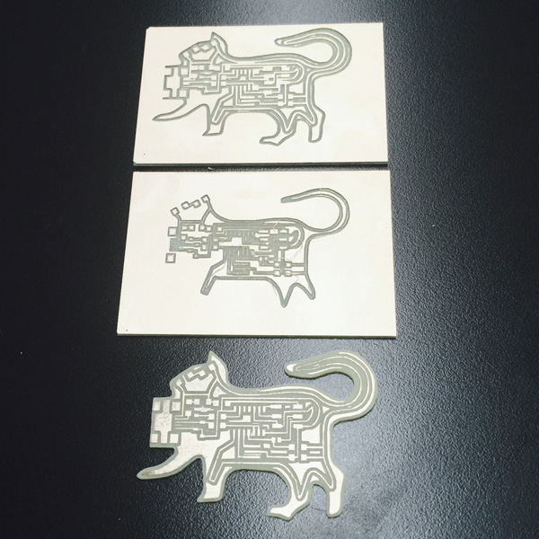
With the thickness of all the lines being consistent and all the solder spots remained where they are, I started to stretch the outer lines to morph into the cat shape. Then I thought it would be cool having the eye to glow, so I was trying to add a LED. Well I didn't know much what was really going on on the board, but I thought I had some understanding of circuits. However, my modified trace started to have mistakes. Note number one: triple check the trace file before cutting.
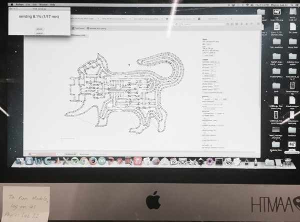
I calibrated the bit on Modela, and caculated the path at default settings. The path looked good at first glance and I was too optimistic because all the critical dimensions were not changed on my new png file. So I sent it to be milled. Here comes the first failure:
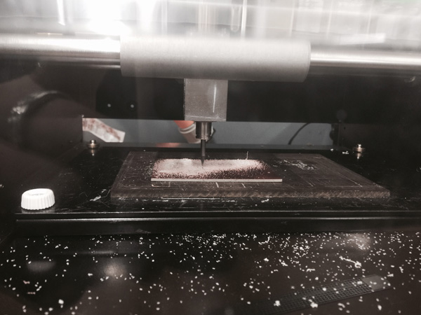
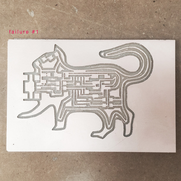
Some thin parts were not cutting through. Instead of going back to the design I decided to give a try changing the tool diameter in the setting. Second mill was not successful either. The third time it finally worked out with the tool dimension being 0.3mm instead.
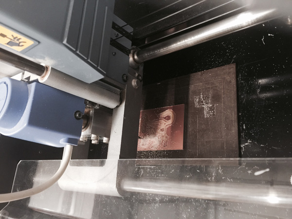
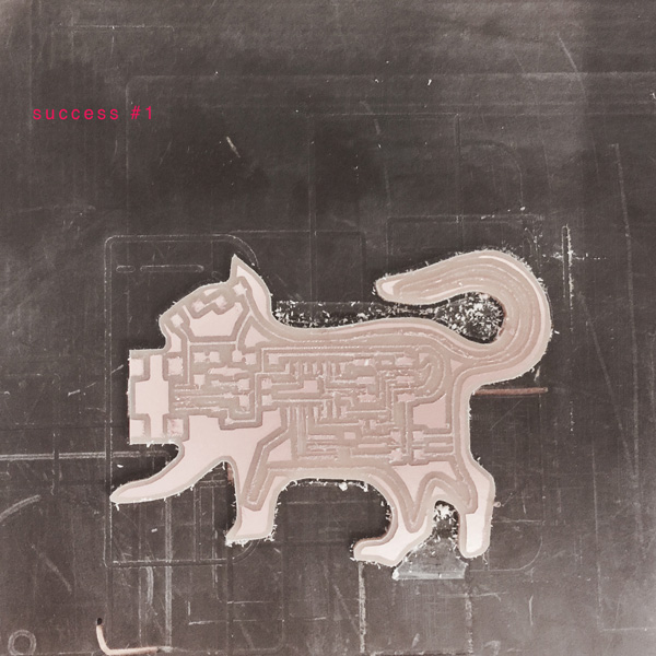
The trace was very thin which worried me a lot. However, since there seemed to have no break on any extra thin line, I thought I would give it a try. So after carefully cleaning the copper surface, it was ready to be soldered.
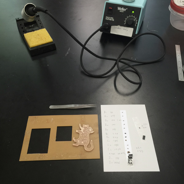
Using the small sheet to get electronic components was very helpful. I did not do a great job on lots of the joints, especially the micro USB port. They are not very pretty, so no zoomed in photo this time....
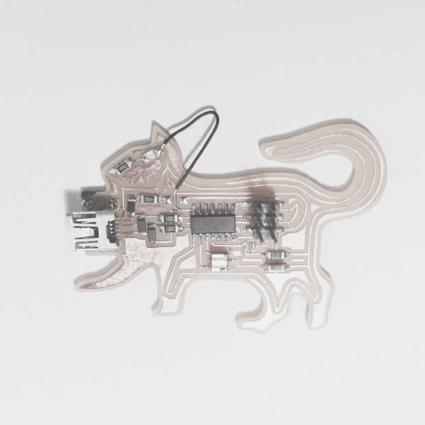
All the parts in place:
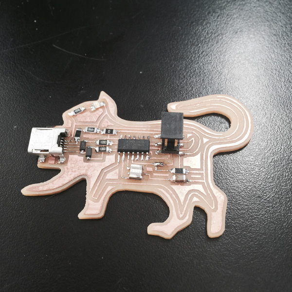
Then I tried to plug it into power.... The LED did nothing.... Here comes the first very basic stupid mistake I made.
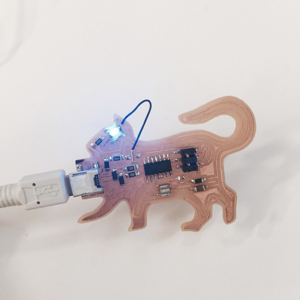
I got too excited about the cat shape. Instead of changing the power line into the cat outline, I should have adding a new parallel line for LED and completely keep the original. Rob and Dixon suggested instead of modify the trace, I could manually break one line and add a short wire to connect the LED to ground, as a "leash"- that was a brilliant idea!
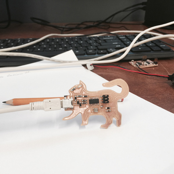
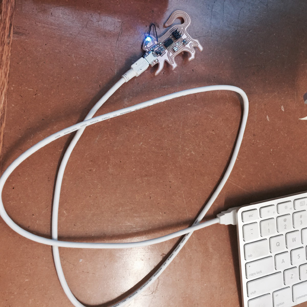
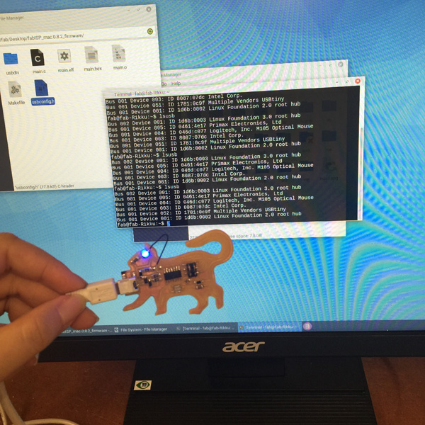
It was successfully programmed from Rob's programmer, jumpers were then removed. But when I plugged into computer to check, it was not recognized. Trouble shooting time again:
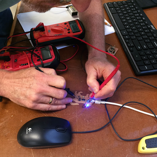
The voltages around the R1, R2, D1, D2 were not quite correct. I first checked the solder joints and they looked all fine. It turned out that was because I missed a small connection while tracing in rhino.
It finally got recognized:
Thank you for reading!