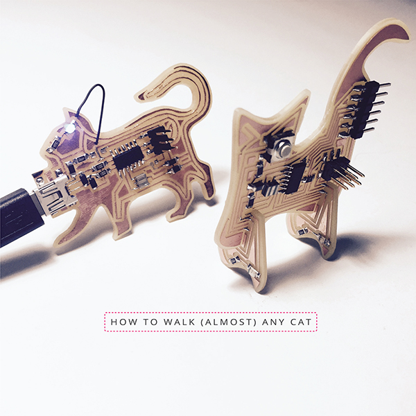
Electronic Design: HOW TO WALK (ALMOST) ANY CAT
Week 05 | How to Make (Almost) Anything | MIT Media Lab | Fall 2016
While making my programmer for the 3rd week's assignment, I traced a ISP board and designed a cat board with a LED lighting up at its eye, a mini USB at its neck, titled "How to walk your cat". This week we learnt how to design circuit board using Eagle. I had a thought during class to make a 3d circuit cat board. And I found out very soon that doing this in Eagle instead of manually tracing is much...harder... Group photo of all my cat boards:
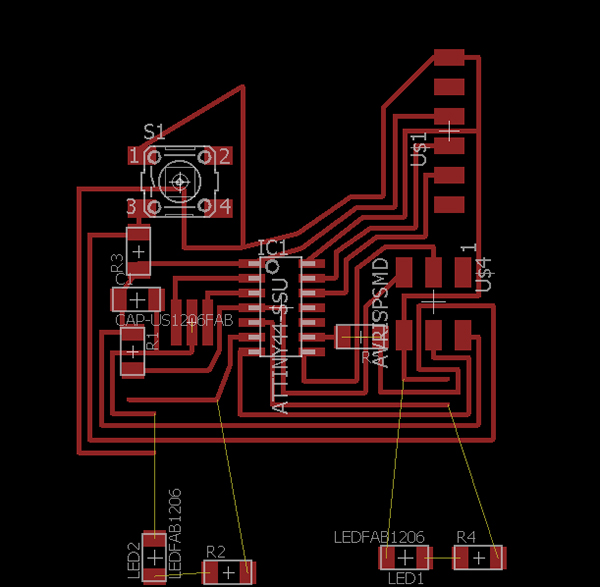
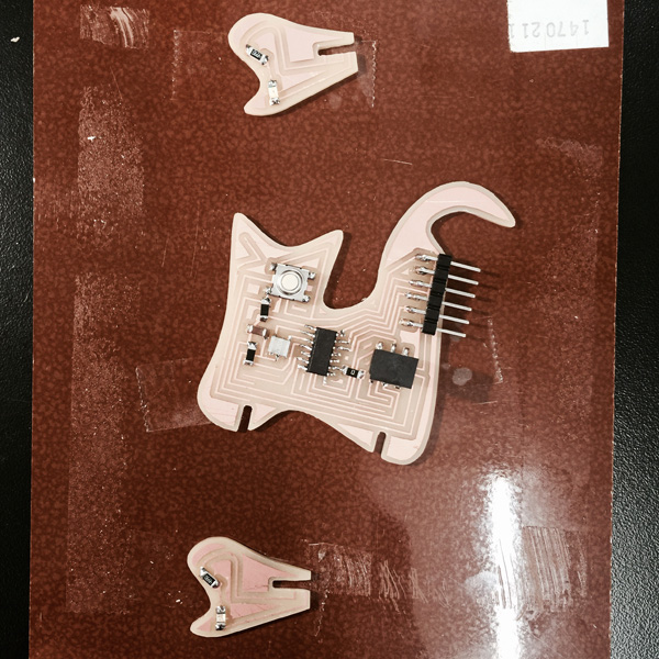
I spent a good afternoon and night in Eagle laying out the components and routing the traces. The SparkFun tutorial was a great help! Since some components I was very particular about where I wanted them to be, such as the button at the eye and the two LEDS at each foot, the board layout was not very efficient, but I managed to get one that has everything connected to where they were supposed to be, with an extra zero resister acting as a crossing wire. Since the legs are separate pieces, I left the yellow lines, and terminate the traces on the main board (one goes to ground, the other goes to IO pins) at each side that would later on line up with the LED three dimensionally. Maybe there is still a better way to route it. (Update 10/22/2016: This design has some messed up routes to the 2x3 header because the errors from my original eagle schematic. It got checked fixed in the week07 assignment.)
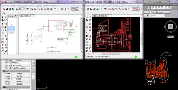
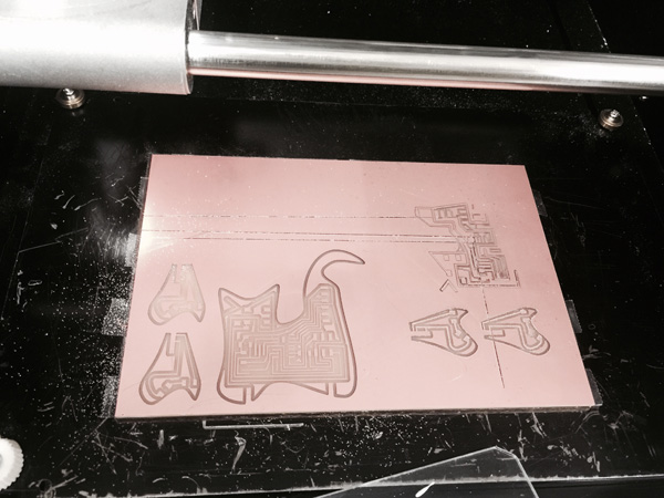
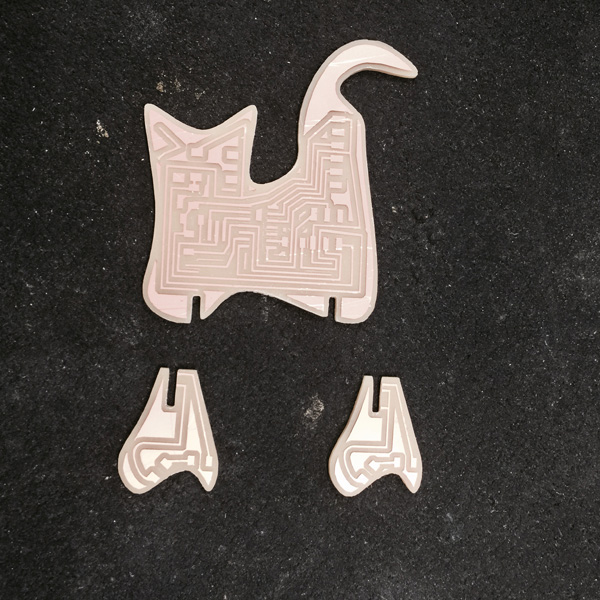
I exported the top layer as a .dxf file, worked on the outline and the notch joints in AutoCAD.
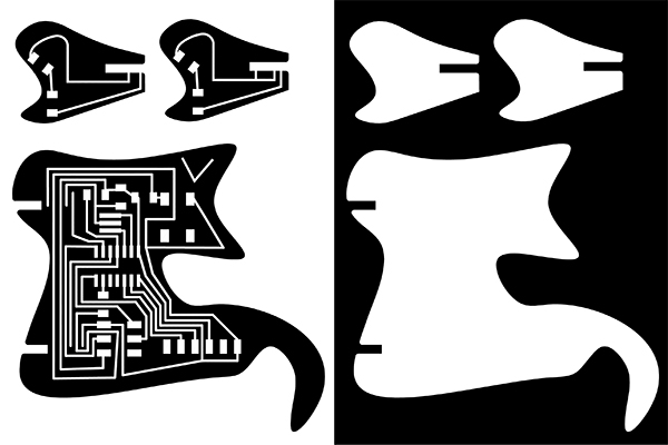
With the default setting for the outline, it was not cut though the board. And I realized that this board has copper layer on both size and that makes it thicker than the smaller ones. I ended up manually peeling off the copper on the other side.
Assembling time!
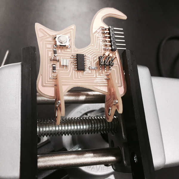
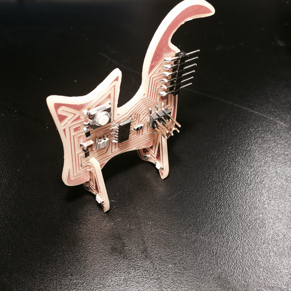
Thank you for reading!