Project Video
What does it do?
I'm an Aero-Astro student and taking this class is one of the best things I've done at MIT. My initial instinct was to build a drone or a robot with some functionalities. Then, I took a step back and thought about what new things I would like to learn. Then came the idea of furniture design. I thought about how cool it would be to design a coffee table with a variable heating capability. The table will be designed with additional built-in capabilities such as temperature sensing, display and temperature control, and capacitive sensing. This way, we don't have to carry around those cheap portable devices anymore, and we can significantly improve the quality of heating by providing power supply from a wall output, rather than a USB which restricts the voltage to 5V and the current to a few hundred milli amps.
I tried to incorporate as many skills as possible from different weeks for this project:
1. Computer-Aided Design (2D and 3D) - table design, eletronics enclosure, button design
2. Computer Controlled Cutting – enclosure for boards
3. Electronics Production – circuit boards
4. 3D Printing – on/off button
5. Electronics Design – circuit boards
6. Computer Controlled Machining – table cutting and fabrication
7. Embedded programming – circuit boards
8. Molding and Casting – heating element (which I later decided to buy for ~$3, in return for uniform heating and better packaging.)
9. Output Devices – heating, LCD display
10. Input Devices – capacitive touchpad, temperature sensing
11. Interface Programming – to connect the input and output devices
12. Communications – I2C protocol to communicate with the LCD display
There have been a few portable devices of this kind, but I would really like to have my own table with all these capabilities plus a temperature sensor, LCD display such that the heating element is flush with the surface of the table and all the electronics is hidden under the table.
What has been done?

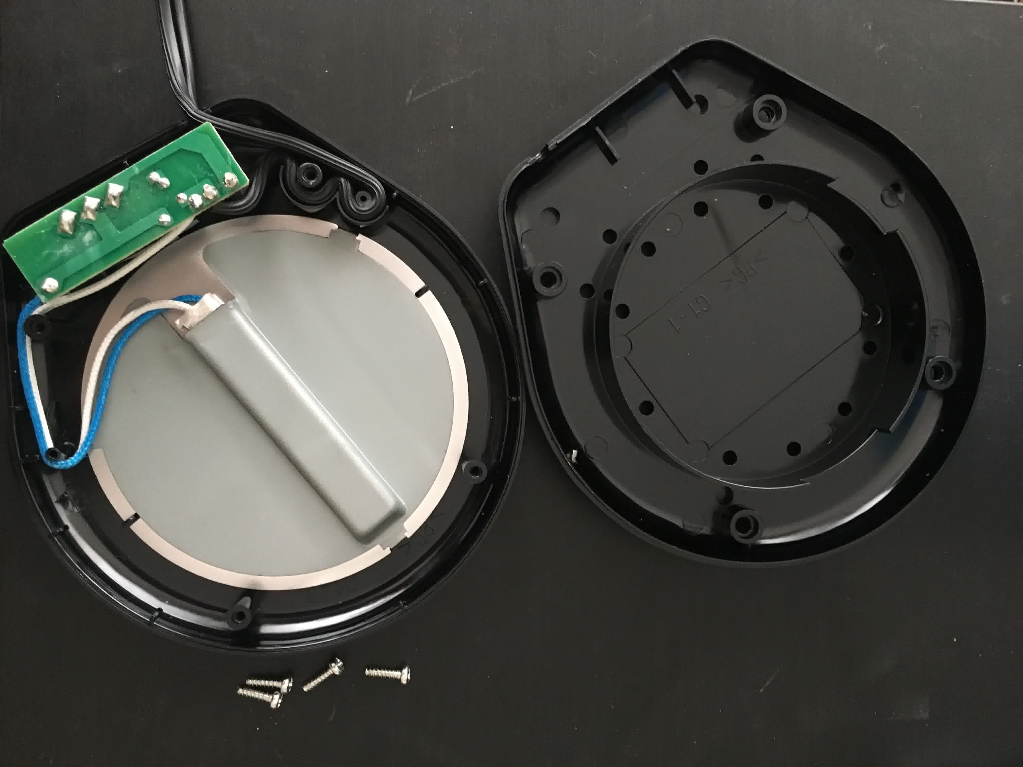
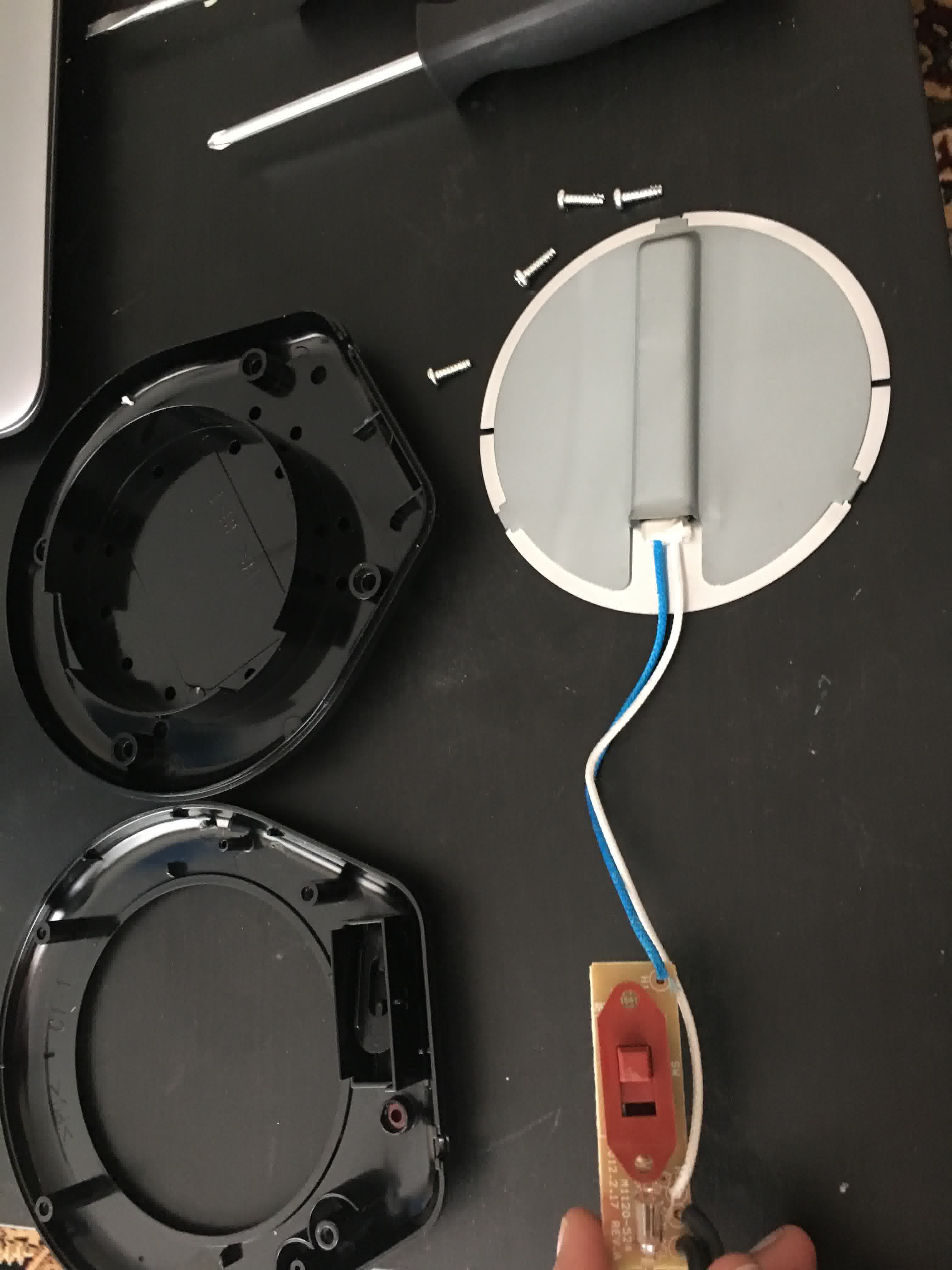
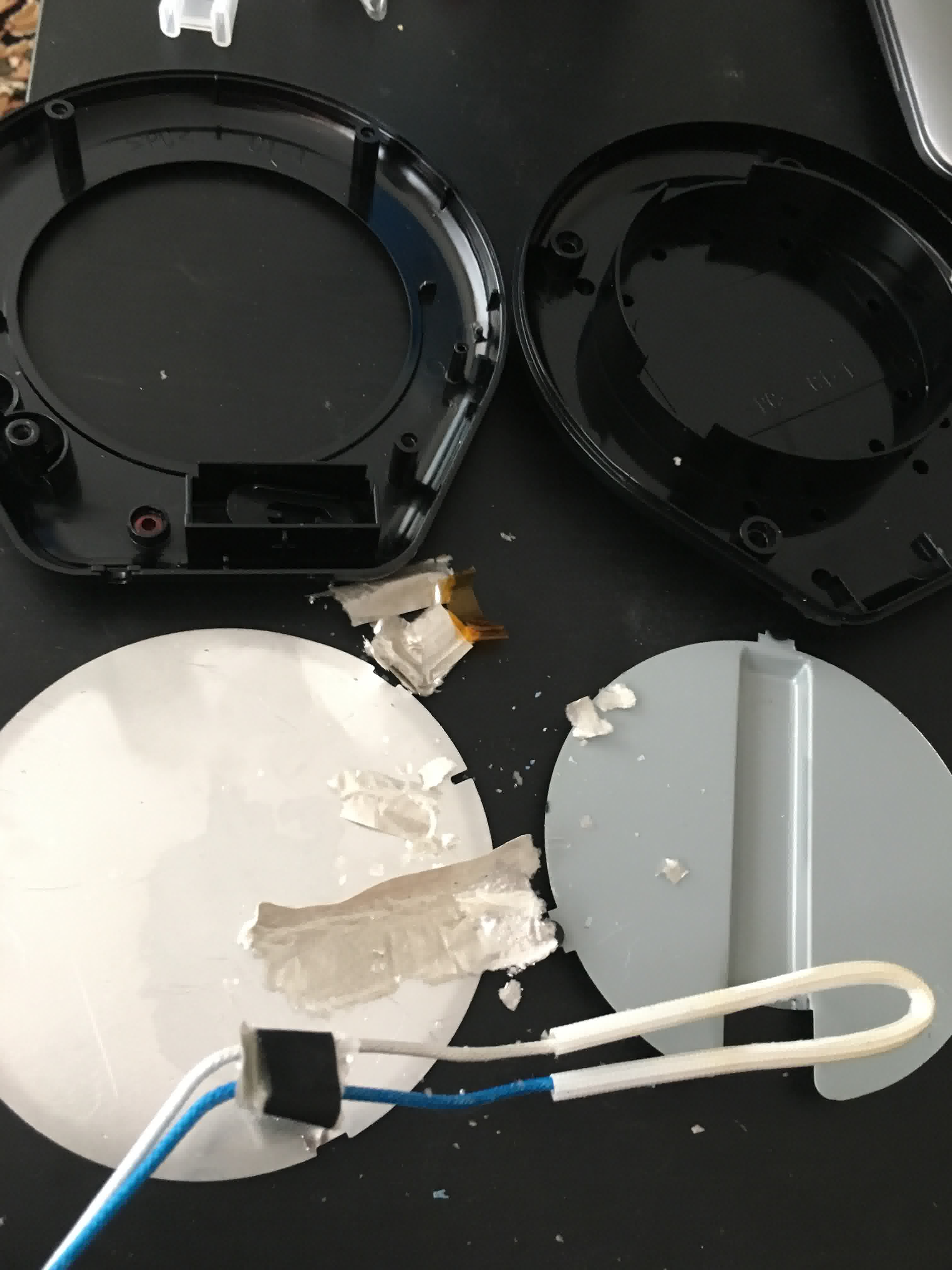
When I opened up the box, I found: a wrapped wire wound heating element that was attached between two pieces of sheet metal, one of which was painted black on the outside and formed the platform for the mug.

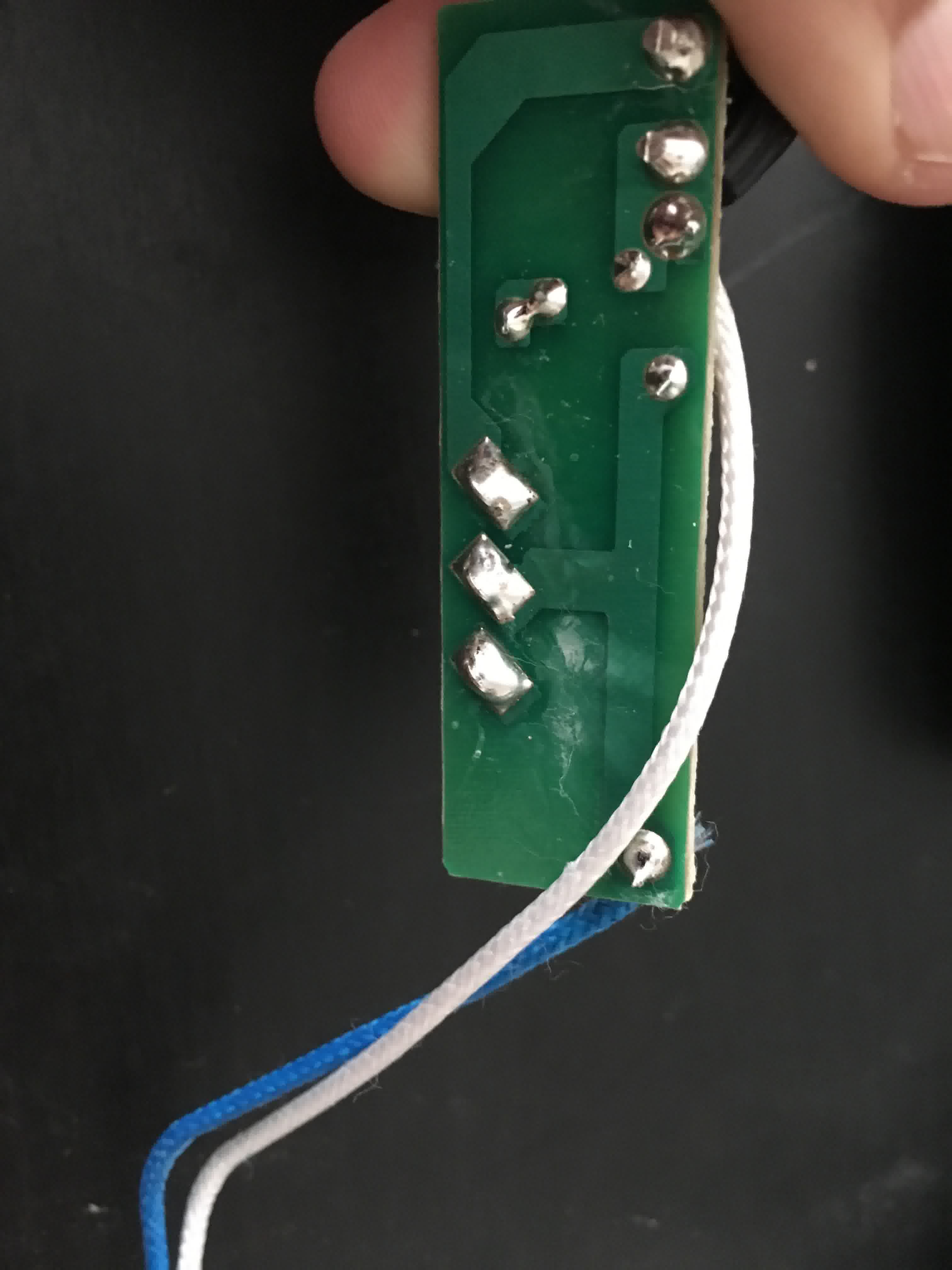
The circuit itself consisted of slide switch, external power supply, output power to the heater, an LED light and resistor. The device consumes 17 W of power. There was no microprocessor, temperature display or control. This made me think that it would be cool to add these features, and integrate with a table. The heating was also not very uniform because of the shape of the element. I didn’t find any product with all of these features, so I decided to incorporate all these into my smart table design!
Furniture Design
As an Aero-Astro student, I have zero furniture design experience. This is my first time designing any type of furniture other than the simple shelf that I made during the CNC machining week. I was super excited to come up with a design that that takes into consideration all the components of the project.I met with Chris, who's the shop manager of N51 shop to discuss my table design, as well as materials, and machining processes. Chris helped me think through the practical application of the different ideas. I had to consider how heat dissipation from the heater would impact the wood. He showed be different types of lumber - maple, walnut, cherry, oak, ash, etc. in the shop. After a long discussion about lumber and birch, I decided to go with birch because it does not wrap due to heat. Lumber expands almost 1/4” for every 20” which is significant especially considering I will have the heat source flush with the table. Birch sheets are available in 5’ x 5’ measurements. So, I decided to make a nice fancy top, and either make press fit legs, or something I can easily attach with screws or glue.
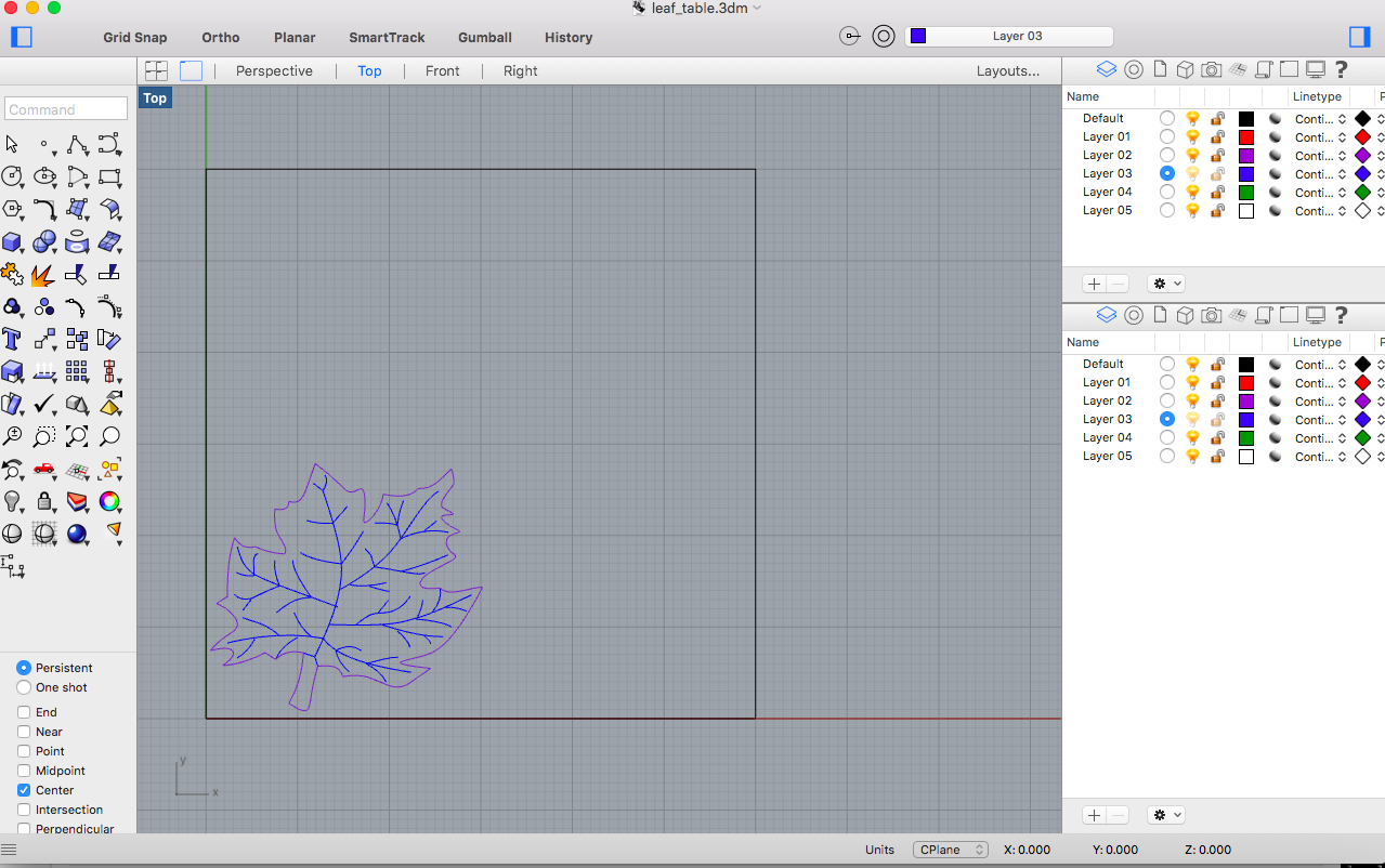
In my conversation with Chris, he mentioned that he only buys local wood to make sure that he is buying only from sustainable forests, and not harming the environment. The connect with nature quickly clicked an idea of making something that resembles a maple leaf, given that winter was setting in, and it reminded me of maple. During the course of the semester, I have learned a few different softwares - Rhino, OnShape, Antimony, and SolidWorks. Because I wanted to go with irregular shapes, I thought it would be easiest to that in Rhino. Although, I don’t like Rhino for a lot of other reasons, it is easy to use for irregular shapes. So, I made my 2D maple leaf drawing to fit in a 30” x 30” area, on one corner of the 4’ x 5’ sheet. The reason it is 4’ x 5’ and not 5’ x 5’ is that, the Onsrud machine in the N51 shop has a bed of 4’ x 8’. So, I will have to cut my sheet to make it fit on the CNC machine bed. Chris also showed me different machining techniques, and demonstrated the lathe (which can be for turning legs into circular shapes with intricate details). He also showed me the the mortise and tenon joint, and how I could make that, if I chose to.

I wanted make system integration as smooth as possible. So, I have identified where all the components should be placed, and how the wires would be routed, and where the electronics components can be placed on the table. Based on that I positioned the legs for the table as well.
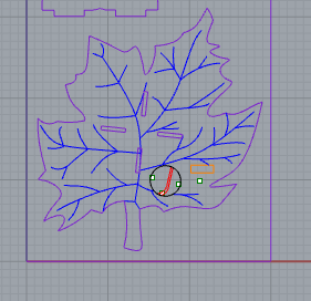
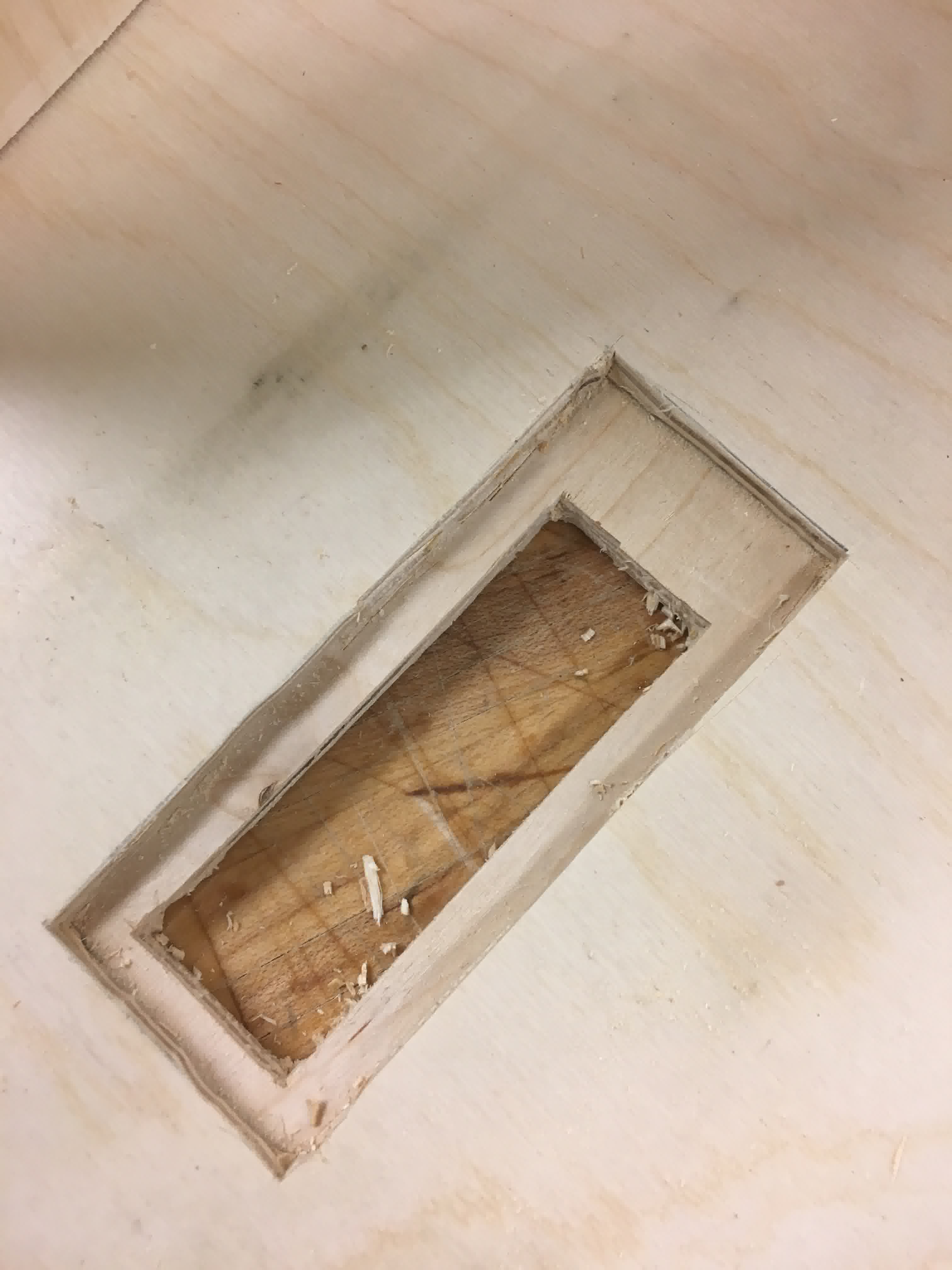
I had to make several other considerations: Add a pocket for the LCD display, and drill points for the button, and for screws to hold the heating element down with copper sheet metal. I also wanted to create a pocket that would hold the temperature sensor under the heating pad. The wire wouldn’t bend very easily so I added some curvature to the pocket.
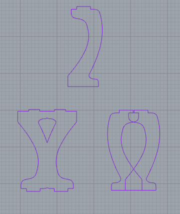
 For the legs, I iterated several times discussing with Chris, and getting some tips on furniture design. And, finally I had three designs for the legs, of which, I decided to go with the one that was structurally robust, and looked quite elegant given the maple leaf design of the table top. I designed the joints between the legs and also between the legs and the table to be press fit.
I first designed legs which were quite thin, and then I learned that the stress on the joints and edges would be too high. so I made a few more designs to make sure that the legs can withstand the weight of the table top. Also, the T joint makes sure that the legs dont bend or break if someone pulls the table by one leg and the other leg gets stuck in the carpet, for example.
For the legs, I iterated several times discussing with Chris, and getting some tips on furniture design. And, finally I had three designs for the legs, of which, I decided to go with the one that was structurally robust, and looked quite elegant given the maple leaf design of the table top. I designed the joints between the legs and also between the legs and the table to be press fit.
I first designed legs which were quite thin, and then I learned that the stress on the joints and edges would be too high. so I made a few more designs to make sure that the legs can withstand the weight of the table top. Also, the T joint makes sure that the legs dont bend or break if someone pulls the table by one leg and the other leg gets stuck in the carpet, for example.
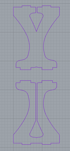
I decided to go with the 1/2 inch Russian birch, given that it does not wrap due to heat, and the 1/2 should provide enough support given the T shaped joint that I will be using for the legs. I also kept the legs sufficiently wide.
Here's the 3D model of the design...

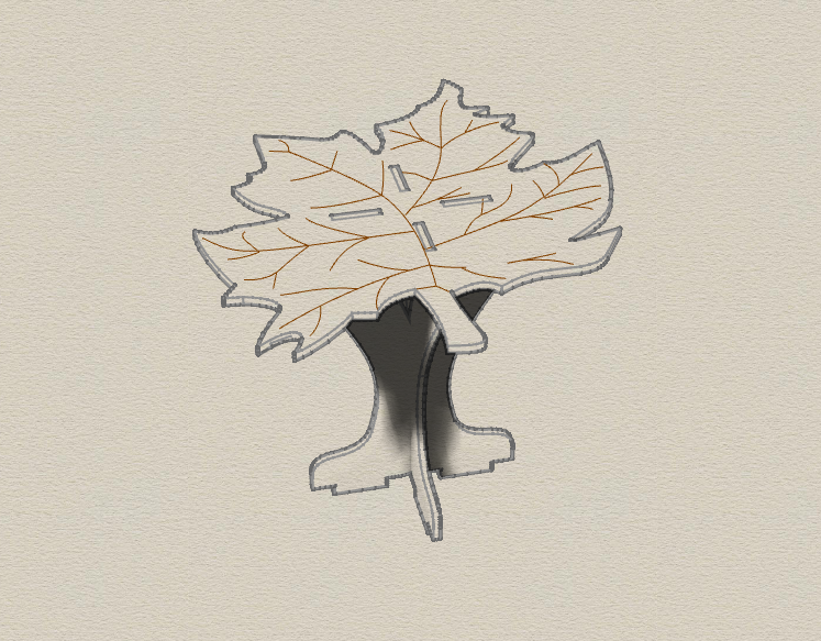

Table Production
I started with merging the Rhino file with Mastercam because I wanted to mill on the Onsrud CNC machine in the N51 shop. With help from Chris, I chose the tools required for the cutting pass, and then an engraving pass. Then, I added pockets to hold the heater+temperature sensor, temperature display, and button.To set up the file in Mastercam, click on File --> Merge. Now the file loads and ready to be set up with the tools we need to cut. We first pick the machine name from the drop down list. Then, we set the stock - in this case, it is 30" x 60" which is half a sheet of Russian Birch. The next step is to set up the toolpaths.
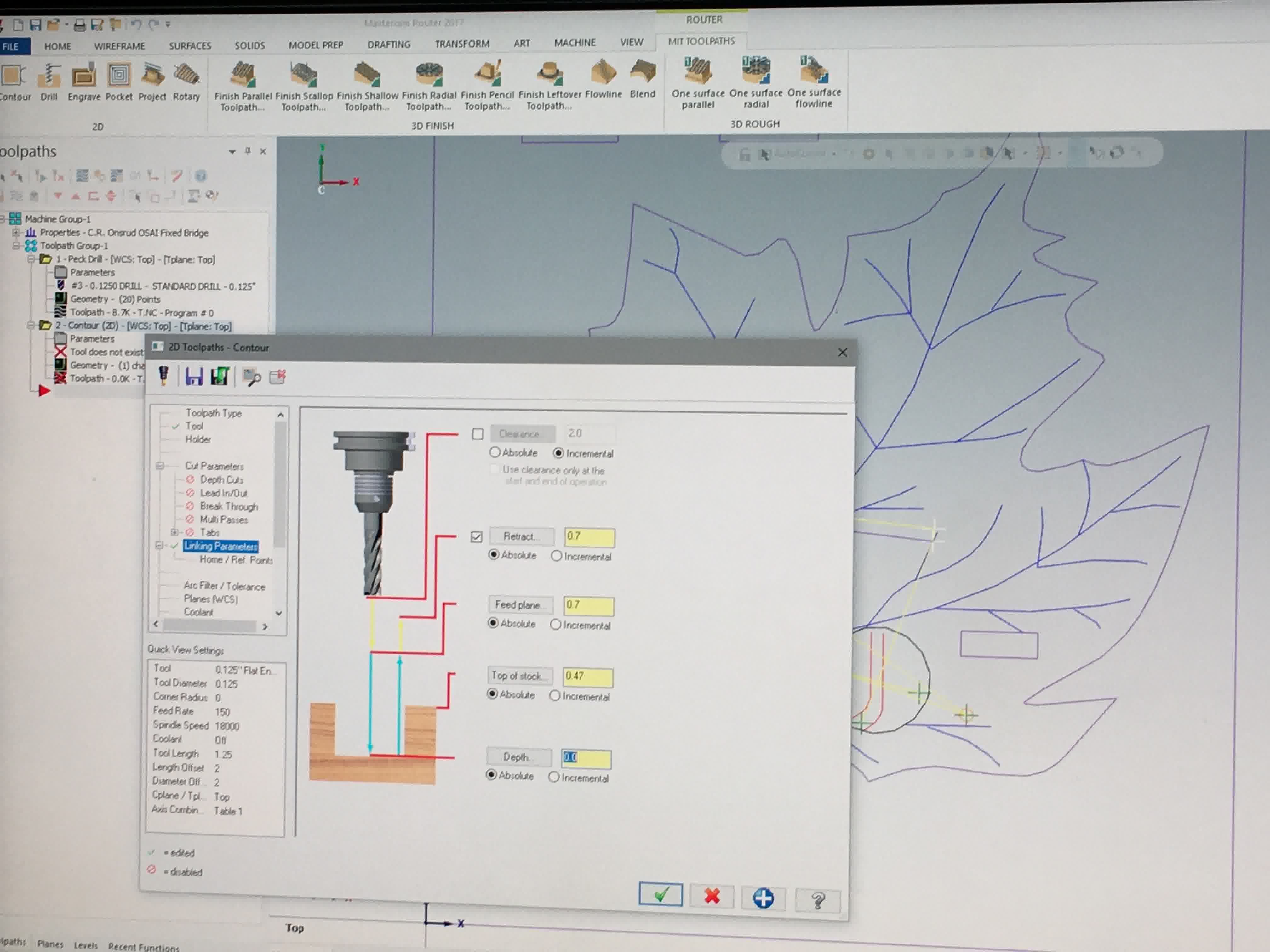
We add the first pass which is the cutting pass and set the tool to 0.5" Spherical end mill. We pick the cut parameters - the feed rate and plunge rate. The plunge rate is always half the feed rate. Then, we pick a smaller tool for the engraving pass and set a very low depth of cut. The third pass would then be the pockets which would use the 0.375" flat end mill. Remember that the corners of the pockets will the curve, and will need to be finished later to fit the LCD display perfectly. We then select all the tool paths and click on Verify operations which shows a simulation of all operations, giving us a beter idea of what to expect when we run the machine.
 We then picked tools and cutting parameters for each part, and also added pockets for the heating element, the button and display.
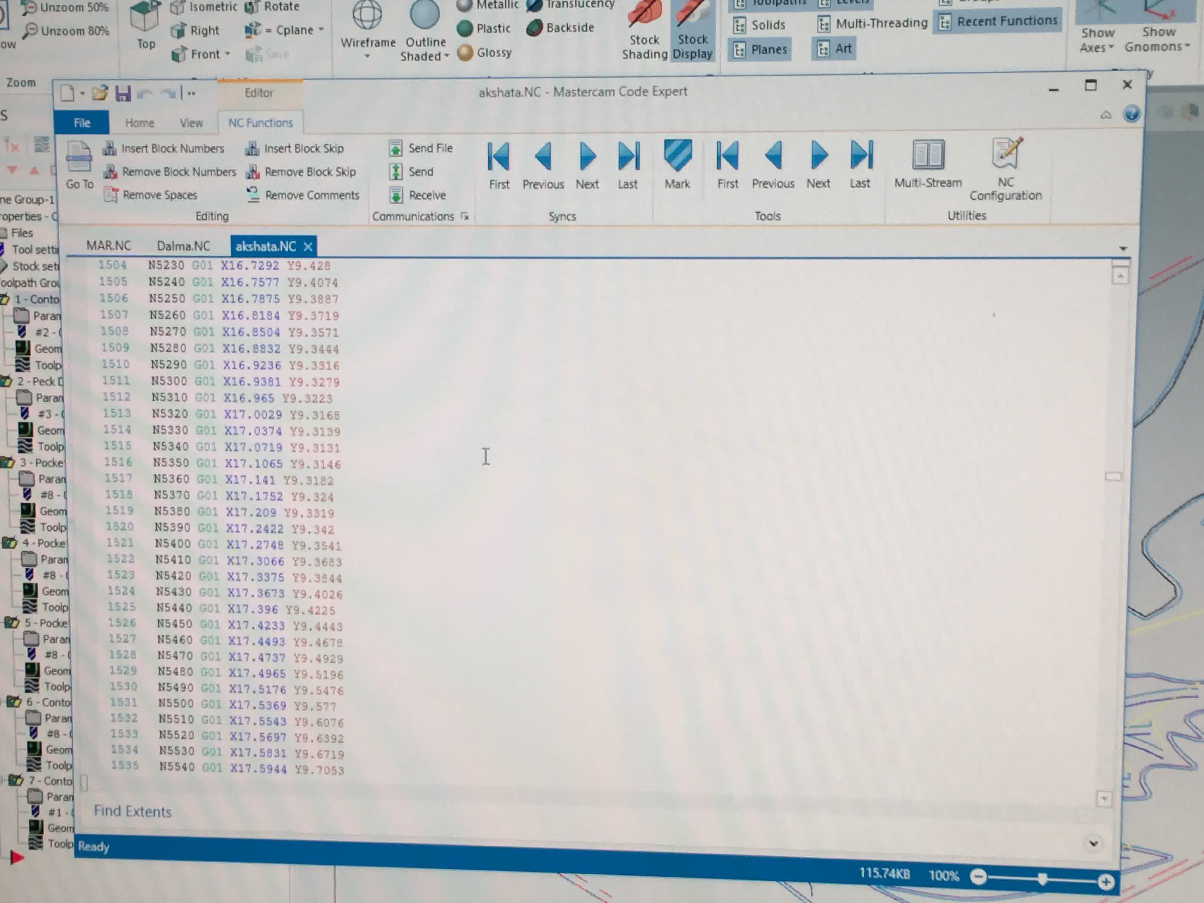
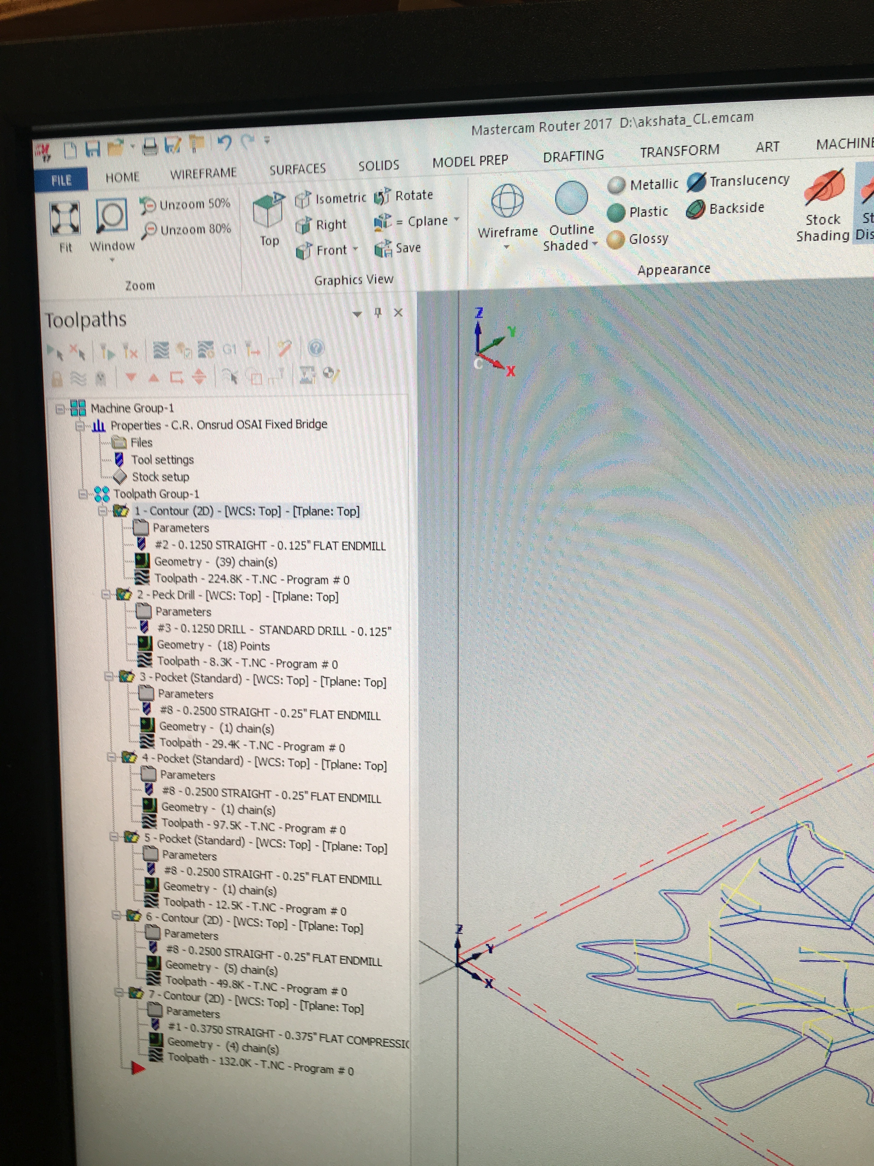 Then we checked that the operations were okay, and produced the Gcode..
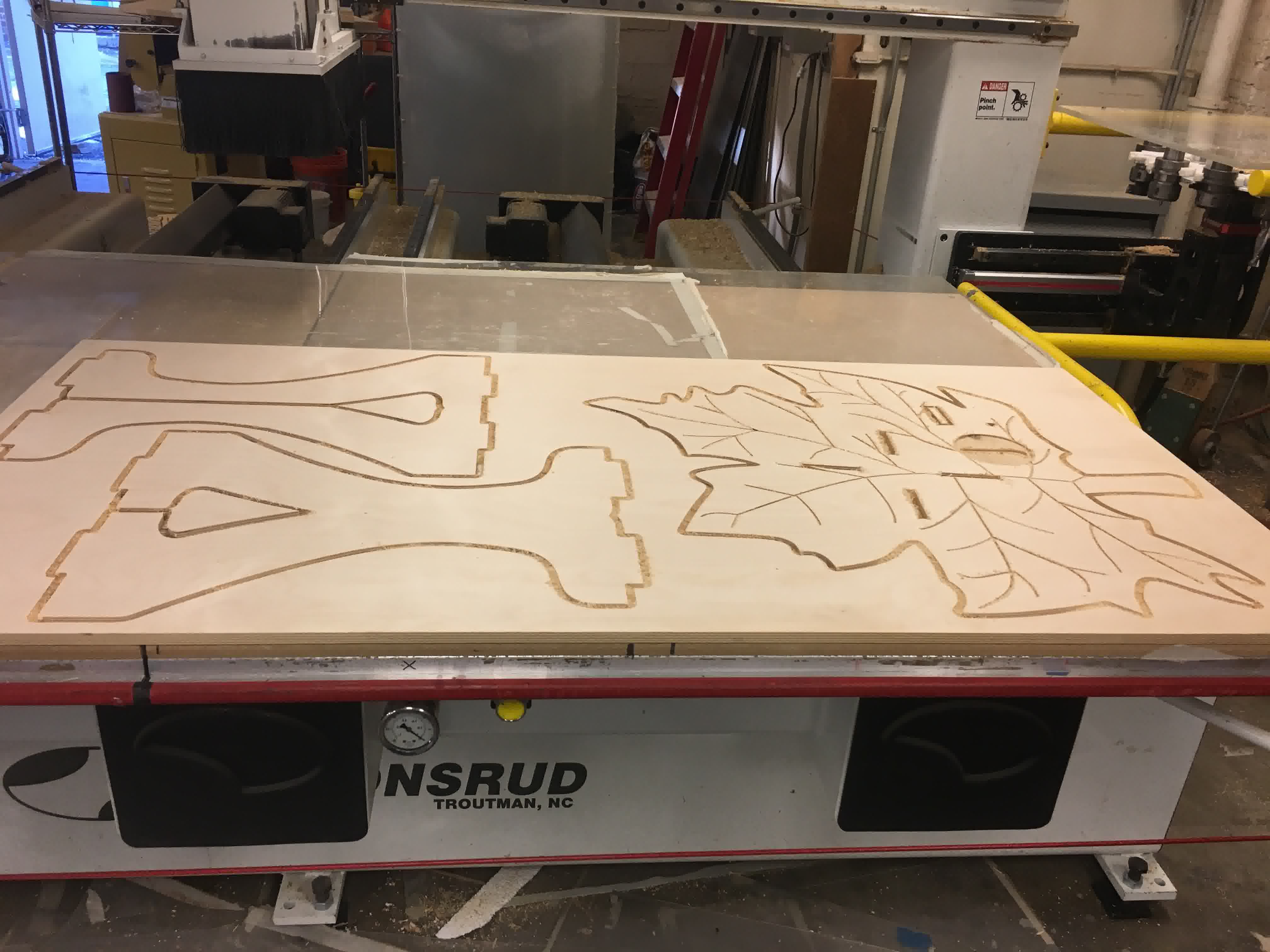
The next step was to cut the Russian birch to half a sheet (30" x 60") on the bench saw, and then fix the wood on to the table and turn suction on.
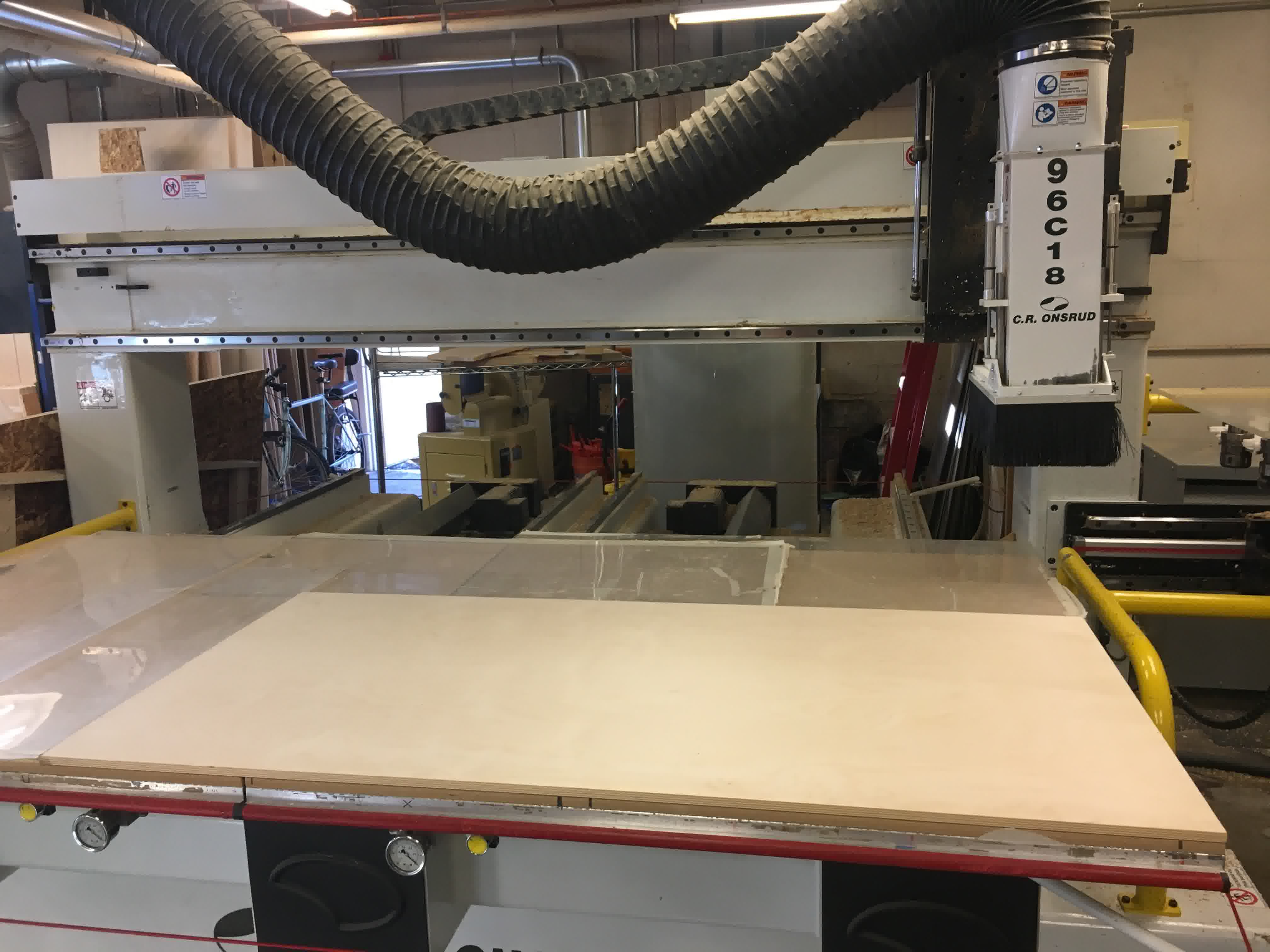
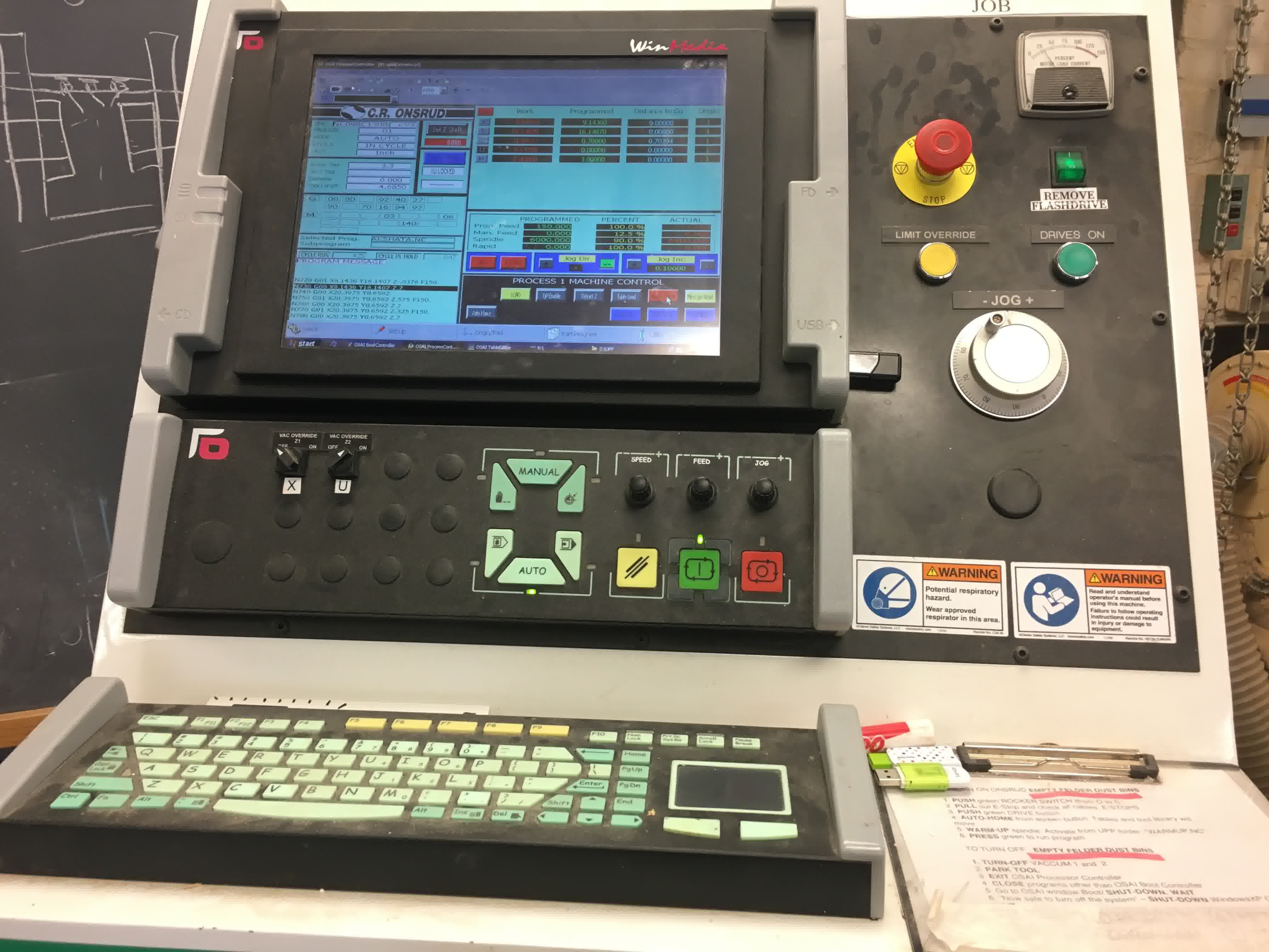
Here's the computer that controls the CNC.. It looks pretty old school, and is very easy to use. Plug in the flash drive, select the file. Open the Gcode, and verify tool numbers, and then press the green button to start.
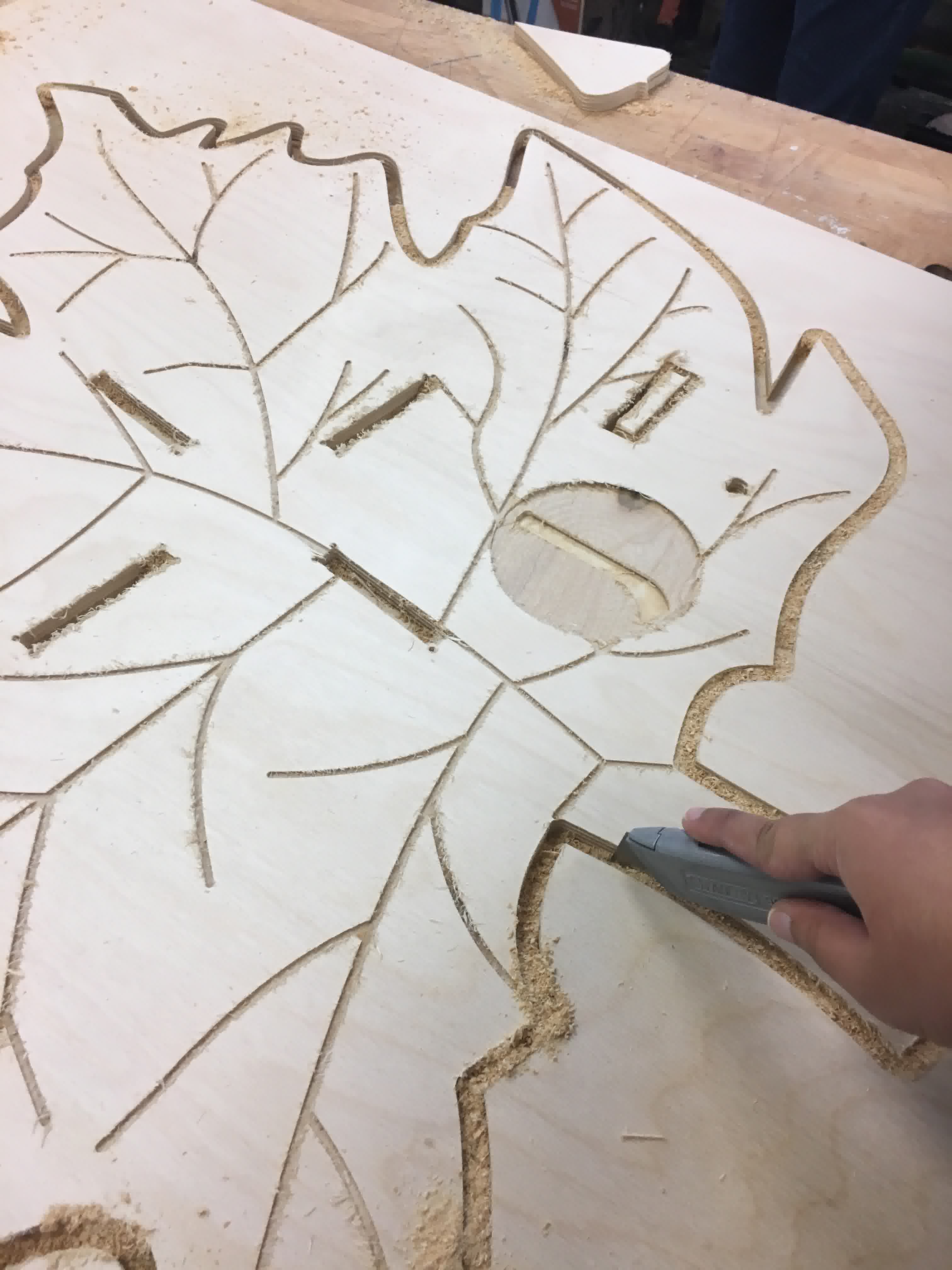
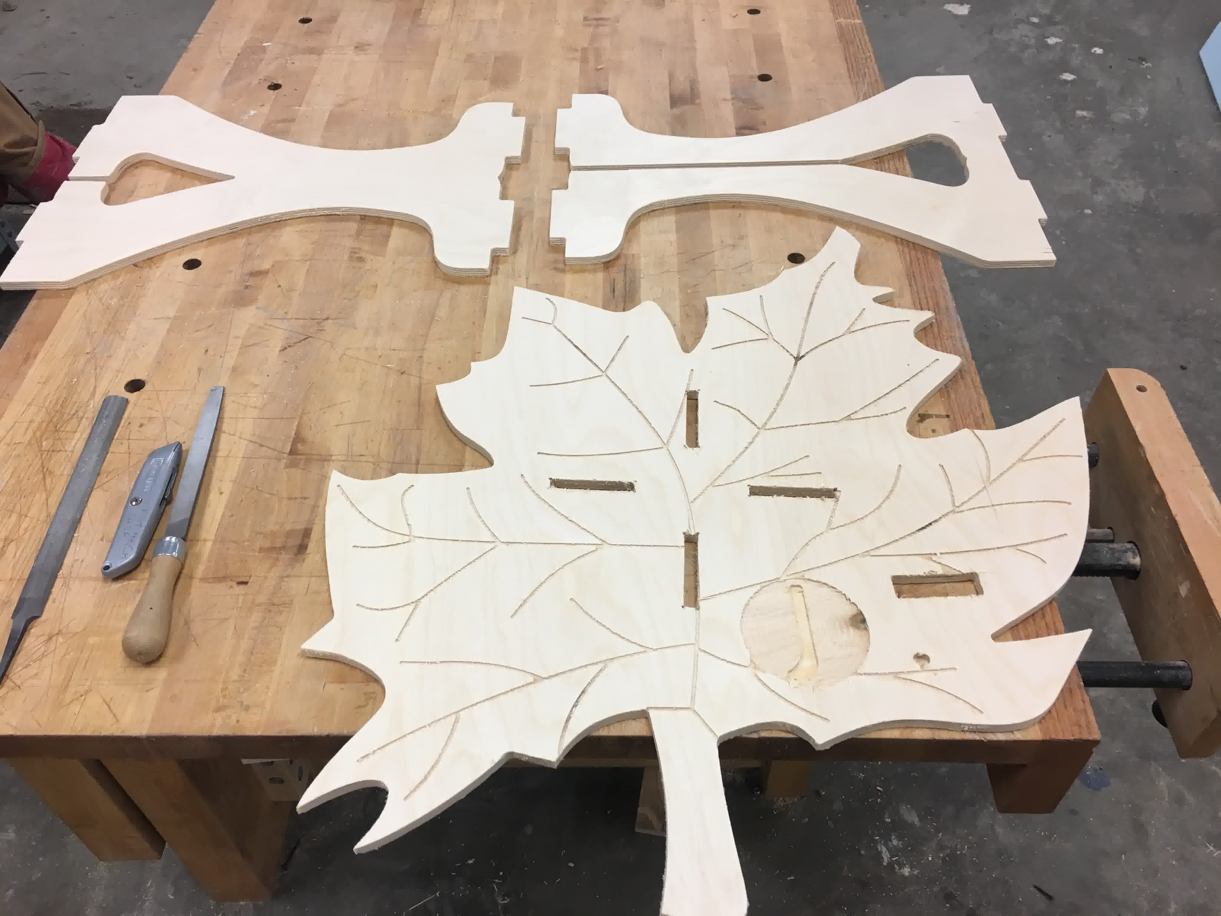
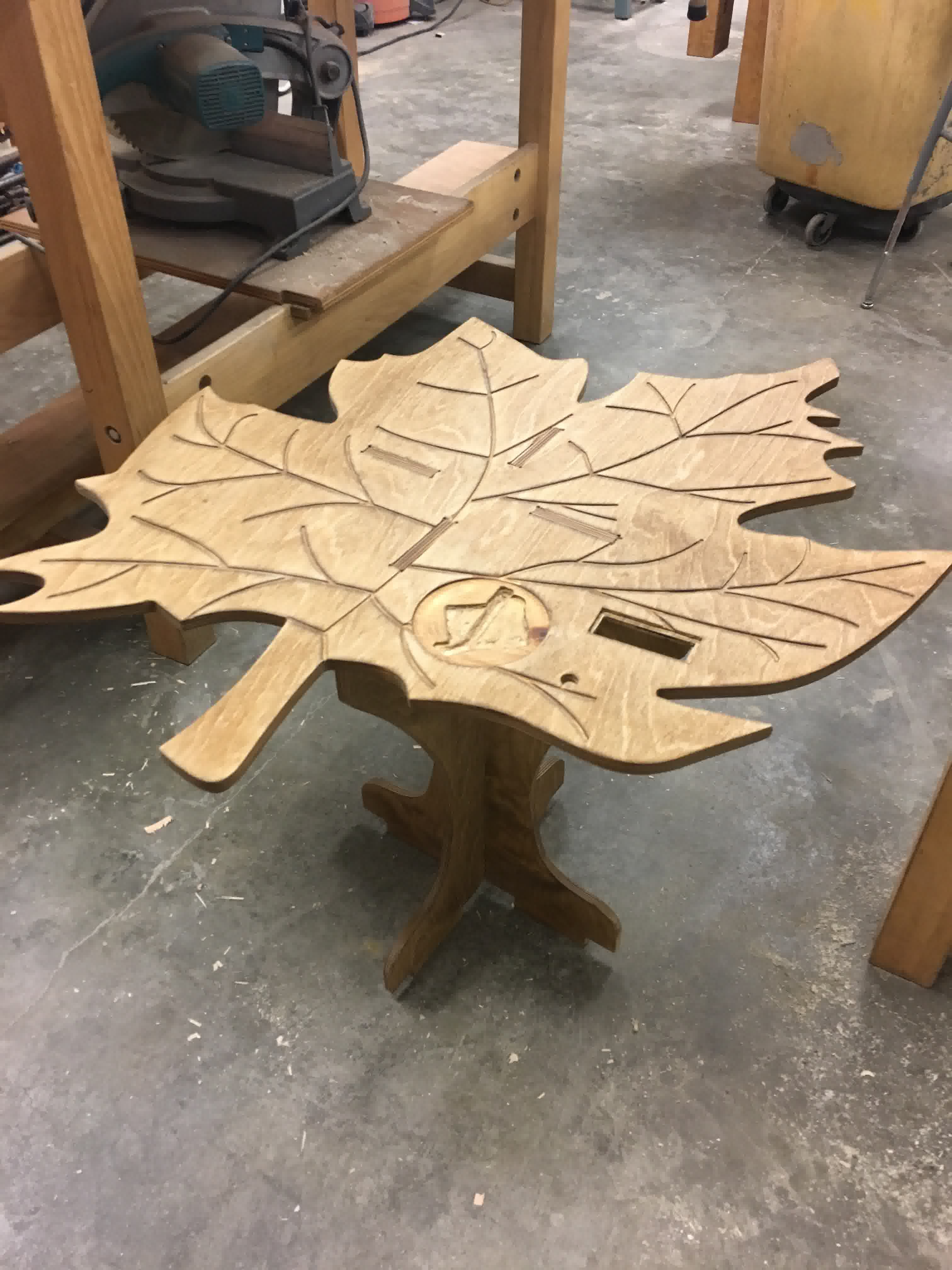
Here are all the parts after the cutting operation. It took me a lot of time to cut the pieces out, and then a bunch of hand work to smoothen the surfaces.
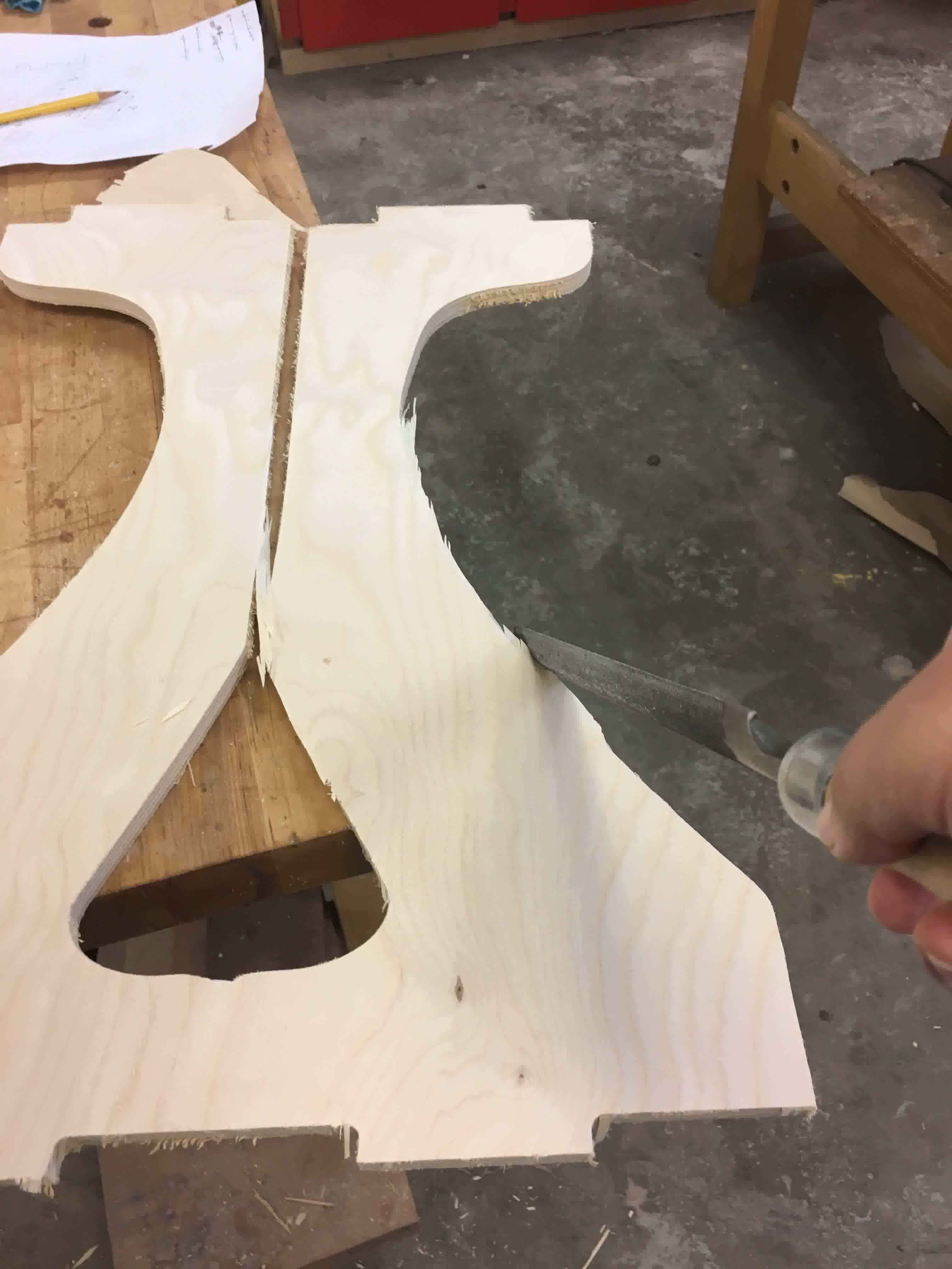
I also had to sharpen out some edges so that I could press fit the parts. I used the band saw for these operations.

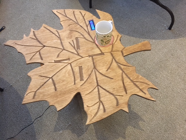
And there I have all my parts ready to assemble!!
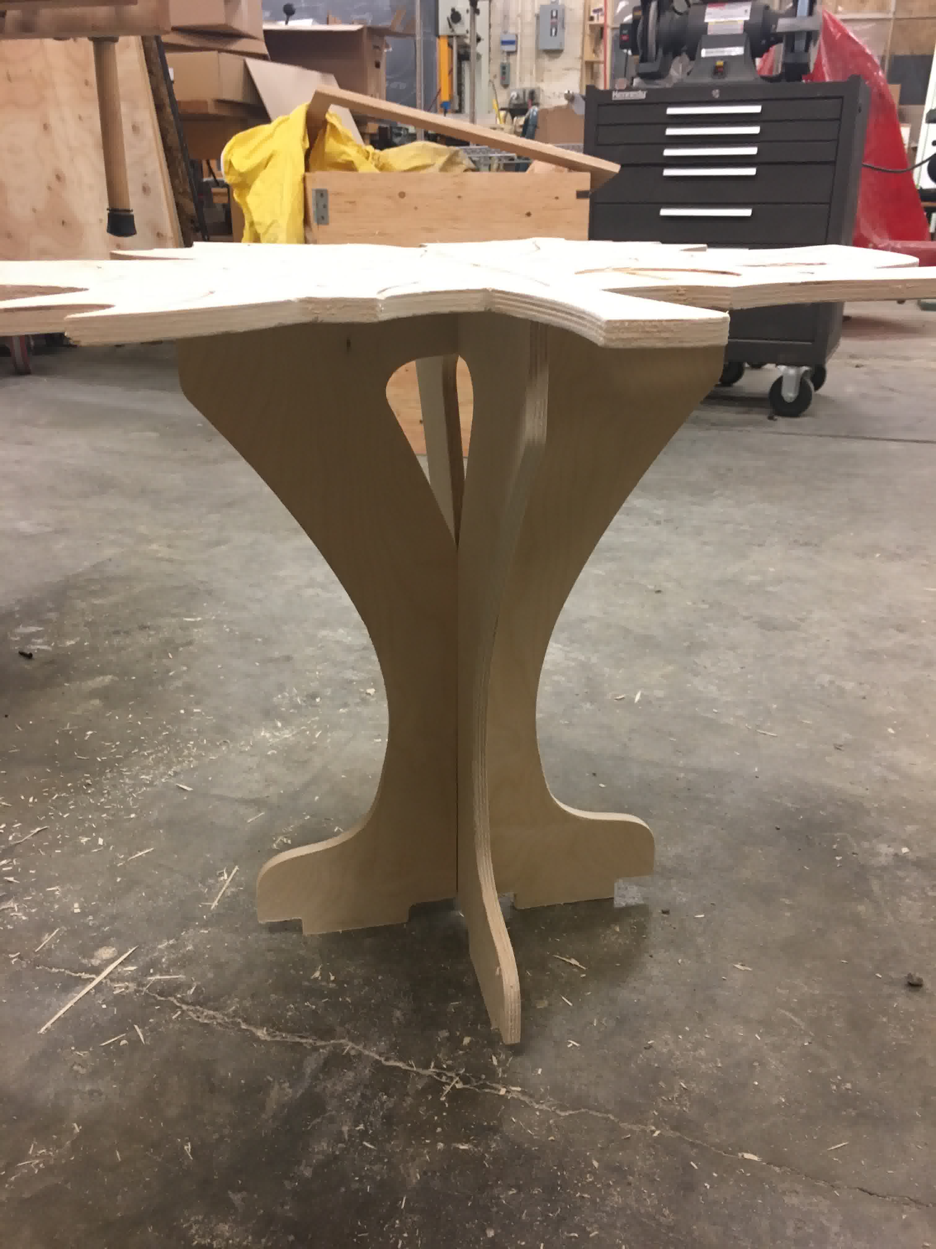
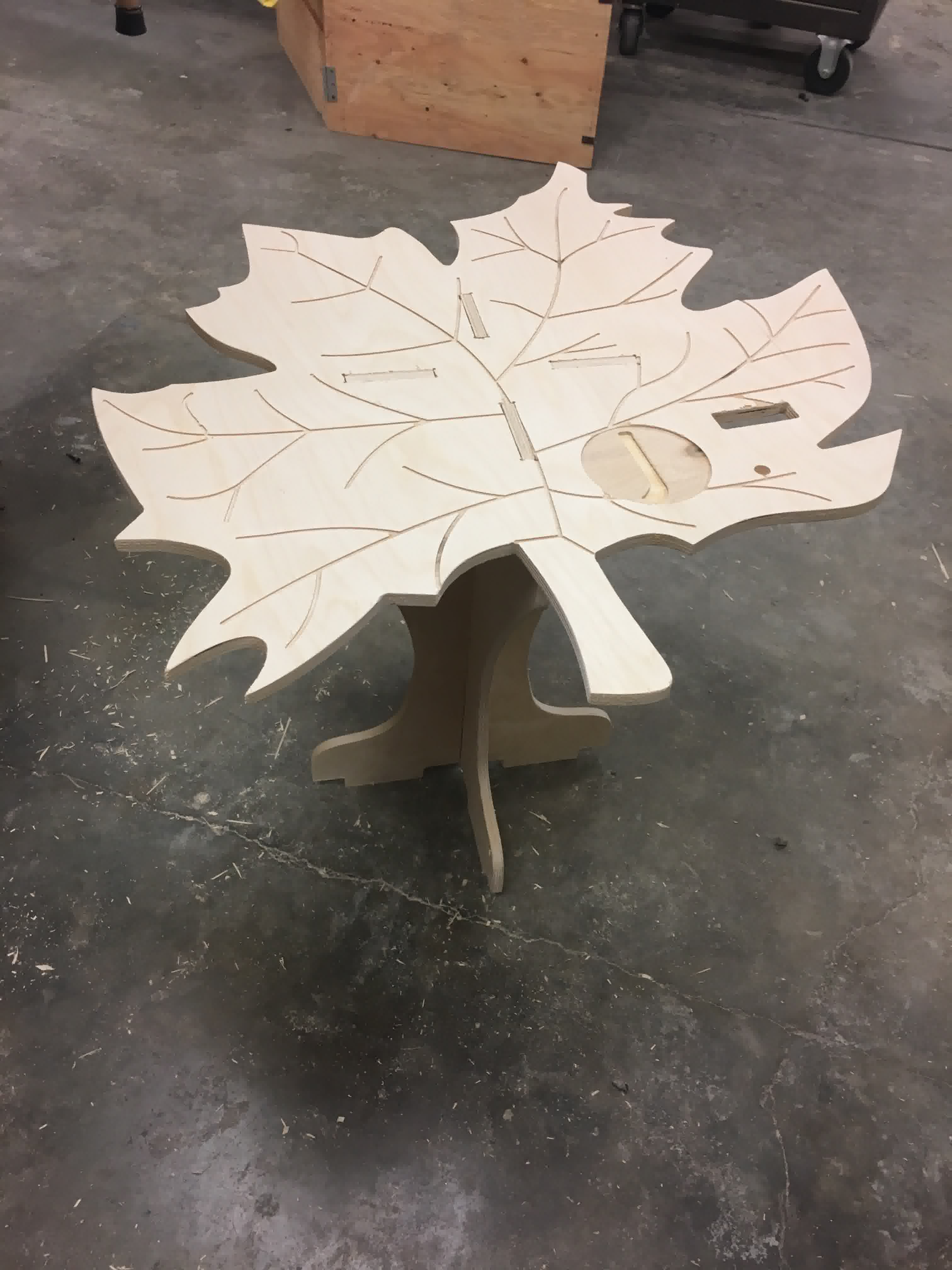
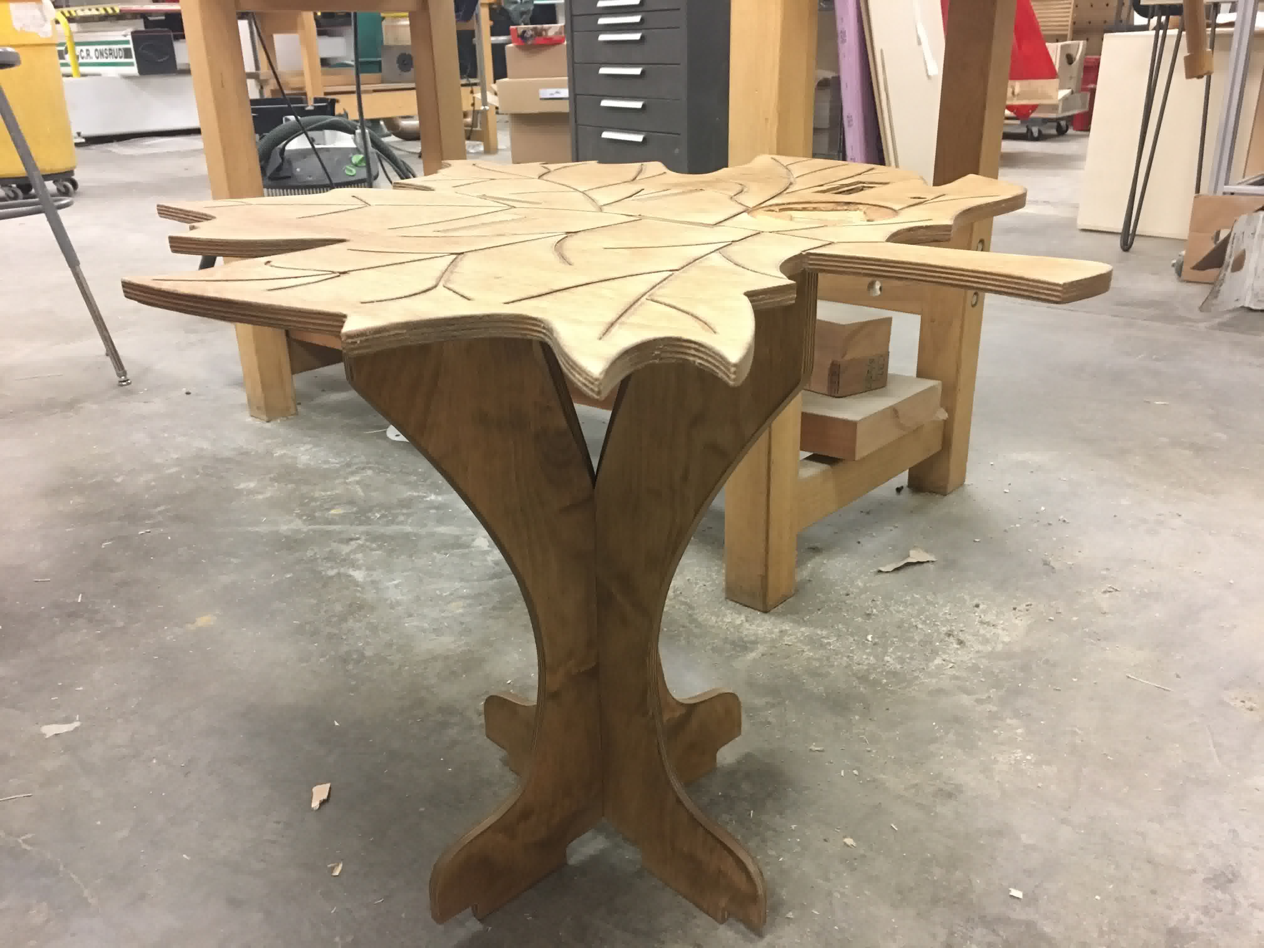
Here's the assembled table.. a few pictures !! So happy to see this product come out so well..


I still have a lot of post processing to do on this, and sand the surface, and put a protective coating etc., which I will do after quickly working on some electronics stuff.
Here are some pictures of all the post processing I did..
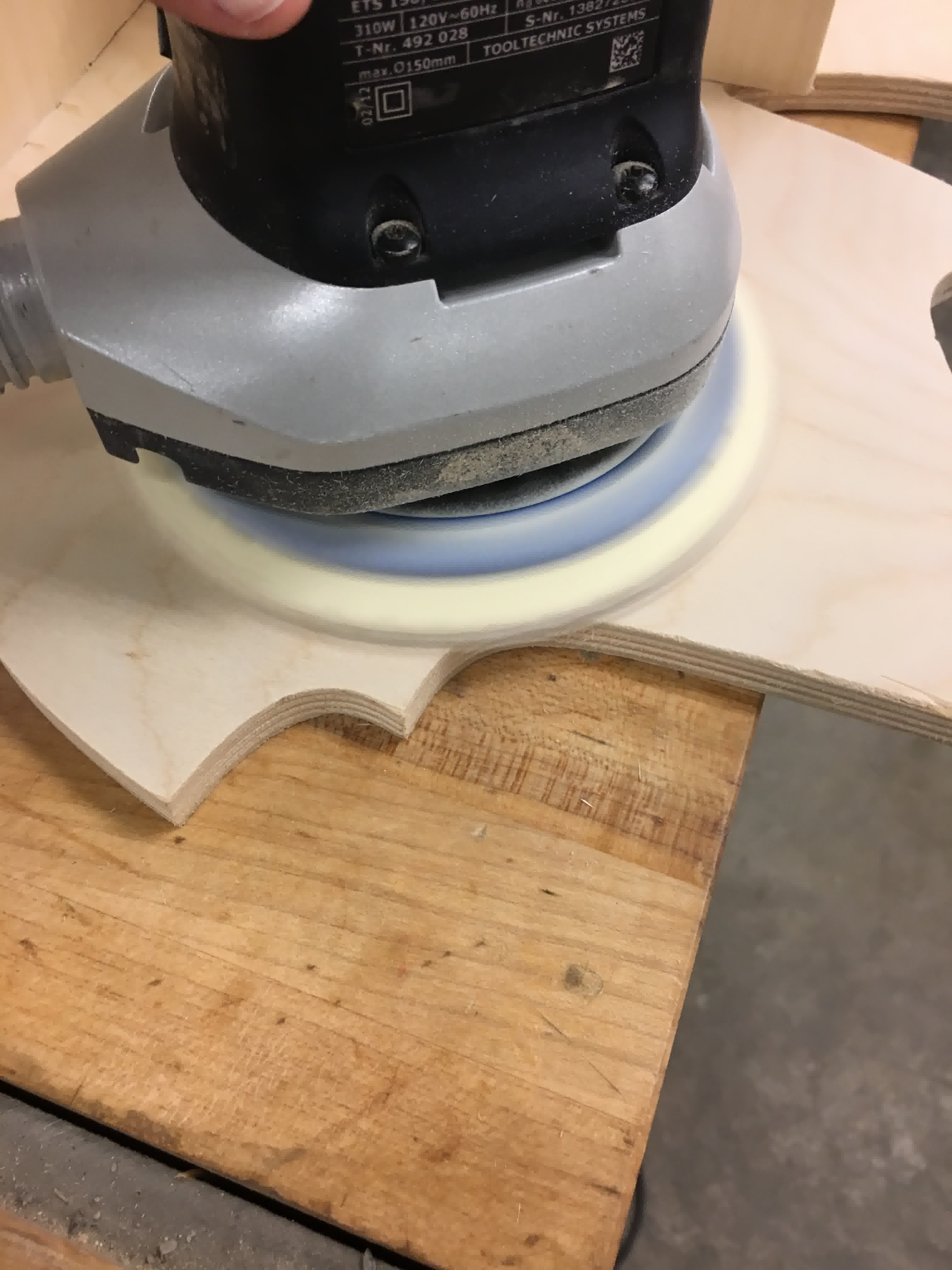
I sanded the surface with the electrical sander and then by hand.. I cleaned and wiped off the surface with a cloth I then cut out the pockets to hold all my electronics snugly.
I then put a few coats of Danish oil on the wood to add some character to it !!
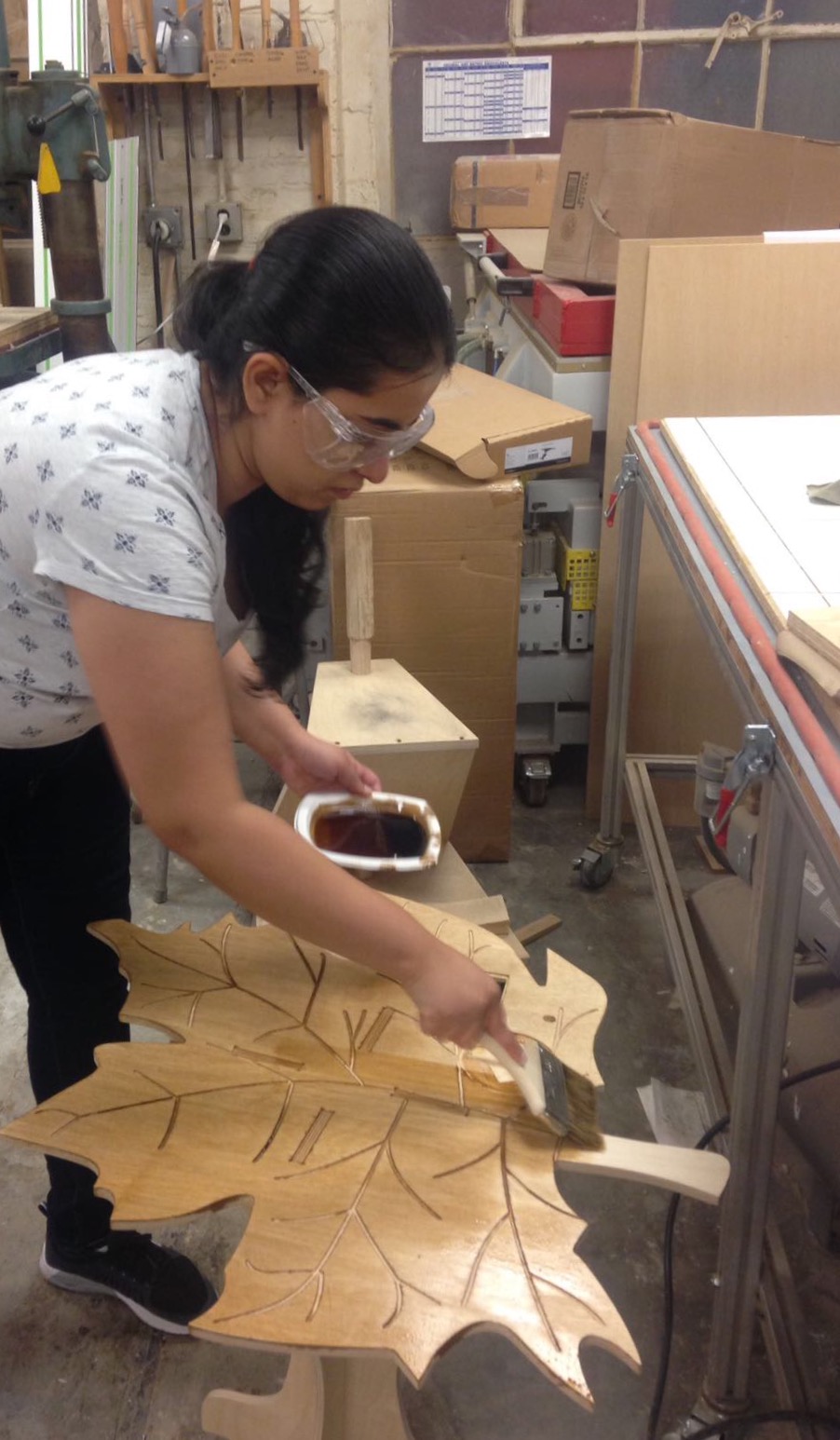
I was really proud of how it looked!!!
Heater and Temperature Sensor
For the heater, I first tried to use nichrome wire. I wound some of the wire around the drystone object that I had cast during molding and casting week. Then I hooked the ends of the wire to a power supply and put in some volts to see how hot the wire gets given a certain input voltage.Once, I had a better understanding of this, I used a weblink that calcuated the length of the wire required, given the gauge, voltage and resistance of the wire. I would then solder the ends of the wire to sheet metal which would be integrated with the table. I realized that this would not be very uniform.
Given that the heating was not very uniform with the nichrome wire, I decided to go with a flexible silicone heater with a 70W rating that I found online. The material has an upper temperature limit of 230 degrees Celcius. So, I had to make sure that the temperature controller cut the power supply off when temperature went above 230 degrees. I planned to attach the heater to sheet metal which would be the surface on which the coffee mug would sit on. The temperature sensor would sit in between the heater and sheet metal.
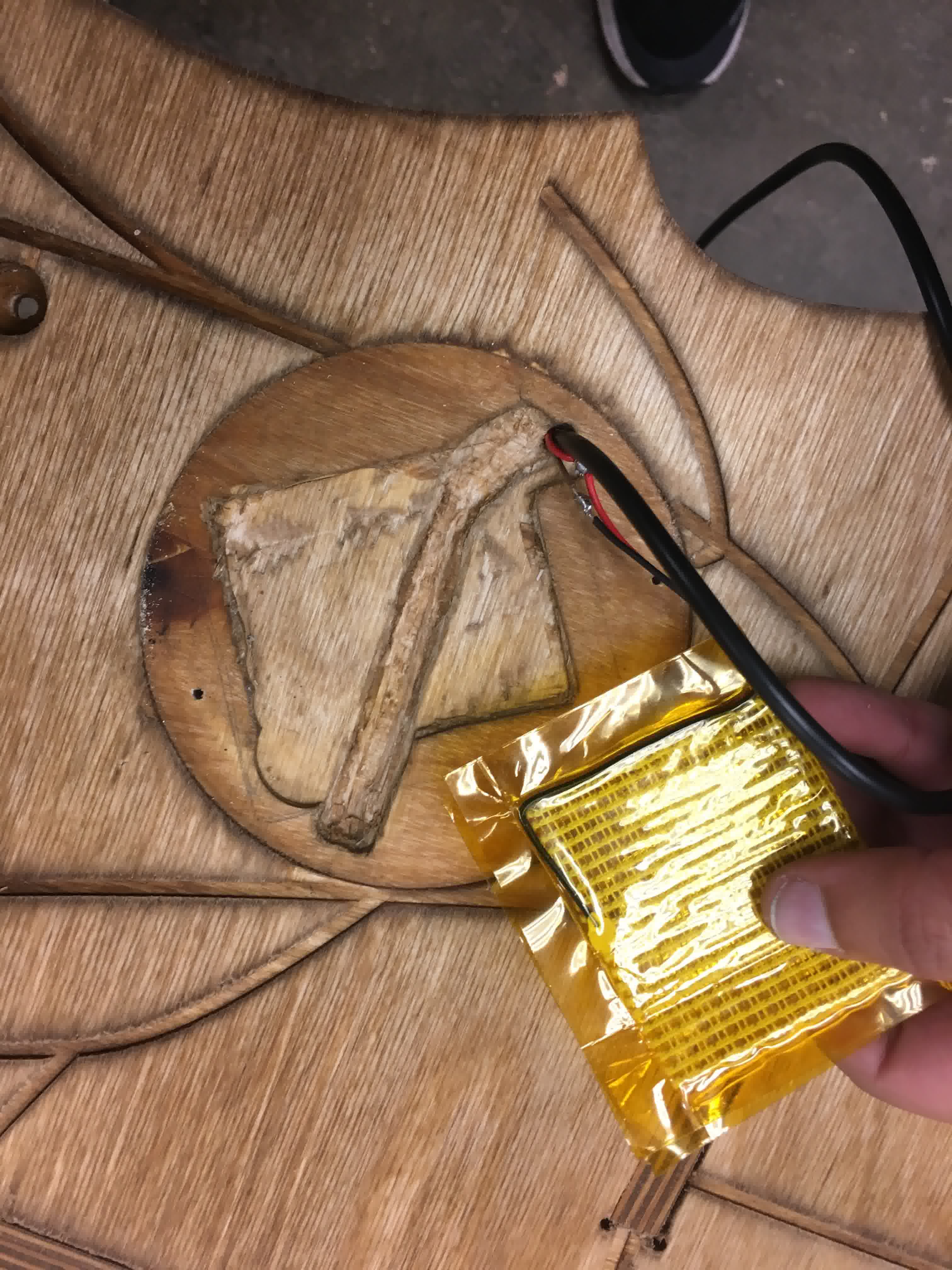
After talking to Jonah, I came to a conclusion that drawing 70W of power from the wall, and working with 110V adapter can be quite dangerous, given that I have no experience working with electrical supplies. I decided to switch to a lower voltage and current rating. I found a kapton flexible heater with nichrome wire embedded in it, which could operate at 5-12V and up to 1.5 A, which would give me sufficient heat and be safe to work with.
For the temperature sensor, I picked a digital temperature sensor which cost $2 on Amazon. The part number is DS18B20 and has good documentation, and is easy to use. It is also waterproof..
Electronics Design
For the electronics, I did several iterations of the circuit boards I wanted to accomplish the task of heating. I started with the idea of wire wound element heating a piece of sheet metal. I test some in the lab, it did seem to get hot. I looked around a bit, and found a bunch of flexible heaters online. I first considered this silicone rubber heater capable of temperatures up to 450 degree Celsius. The power density for the heater was 10 W/in2. So, the wattage required was 70 W. The advantage was that it would heat quickly, and would be capable of much higher temperatures.The downside was that it was relatively expensive ($26) and the heat would be too much to dissipate through wood. There is a chance that it could degrade the wood. So, I decided to go with something rated at lesser wattage. I bought a flexible caption heater that can take up to 12 V, and ~1-1.5 A. I read the data sheet, and decided that this would be perfect for the application. It would reach temperatures of 125 C quickly, and would not dissipate too much heat compared to the previous option. I ordered the component on Amazon.
Next, how would I pull the amps I need to heat the caption heater? The Arduino pins give a voltage of 5V and current of a few tens of milliamps. This wouldn’t be sufficient for our purpose. I found a wall adapter rated the would provide an output variable voltage of 5-12V and current of 2A.
Then, I picked out the N-MOSFET I would need to pull amps from the external power source. I read several forums to understand how this circuit works, and what components I need.
The heat dissipated can be calculated as 12 V * 47 mohm = 0.06 W which is not too high, so we won’t really need a sink on this circuit. But if it exceeds a few watts, I would definitely need a heat sink.
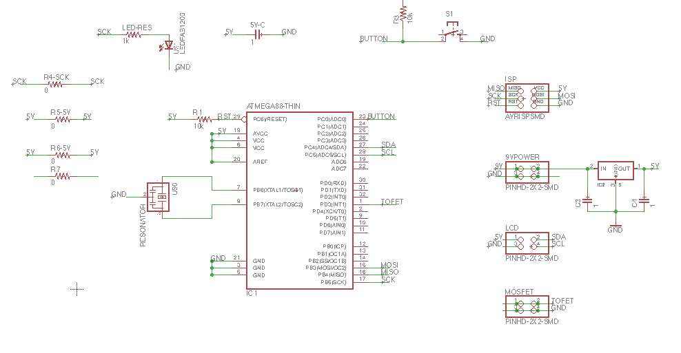
I decided to use the Atmega328P-AU as my microprocessor given that I had sufficient documentation available online to design my circuit. The pinouts for the processor are shown below:

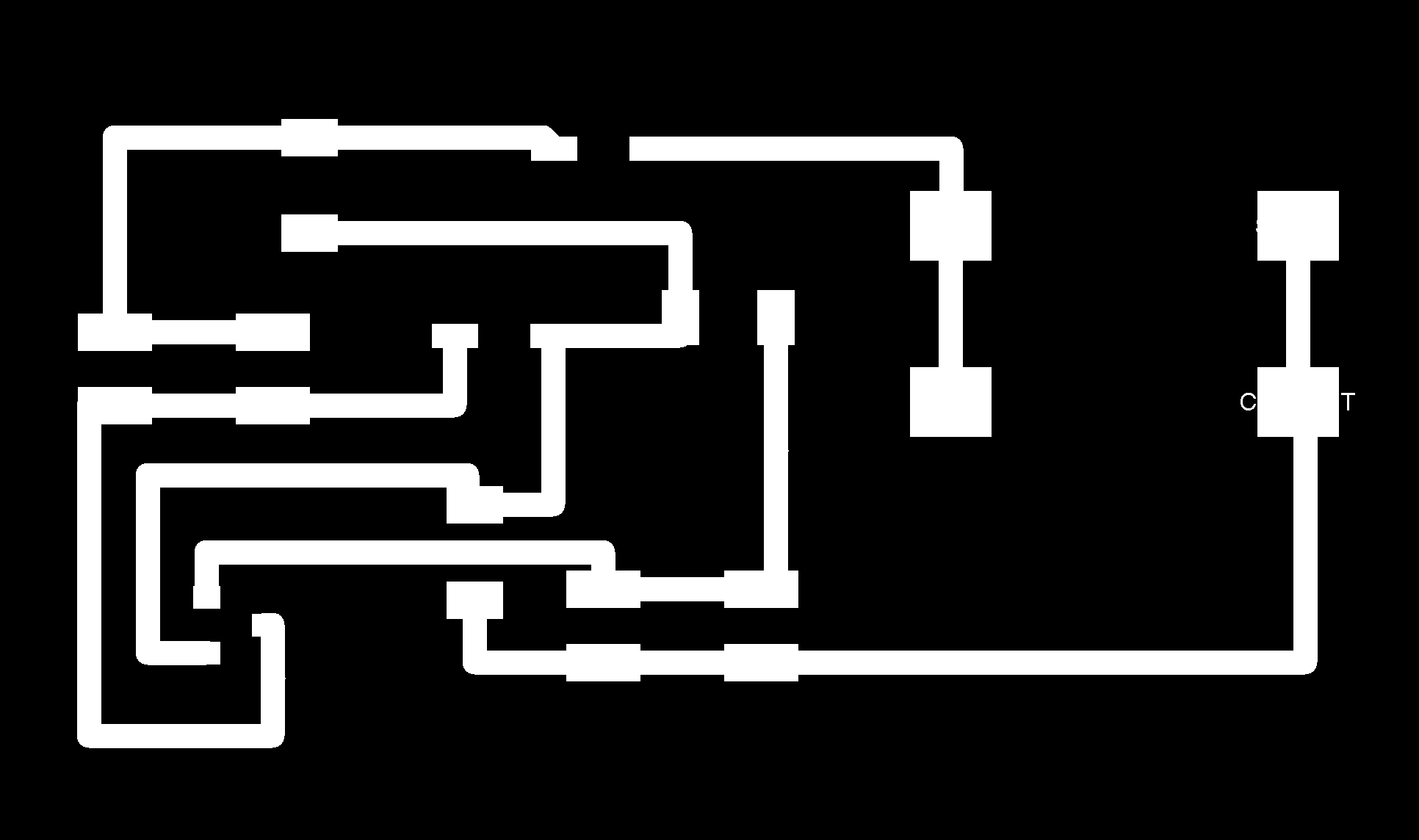
By now, I am quite proficient with making schematics in Eagle. So, it was pretty quick. But what I didn't expect is how hard routing was going to be.
I was working with the Atmega328 for the first time. And, routing for this was a nightmare.. It took me 2-3 days just to get the routing right and to make sure there were enough clearances between lines, and these would actually mill properly.
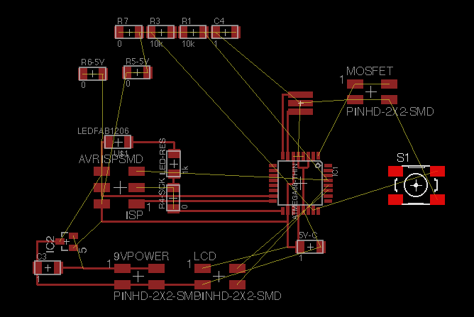
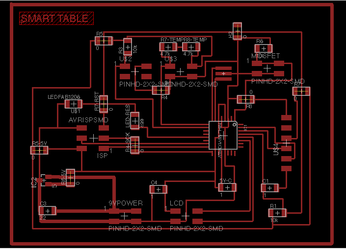
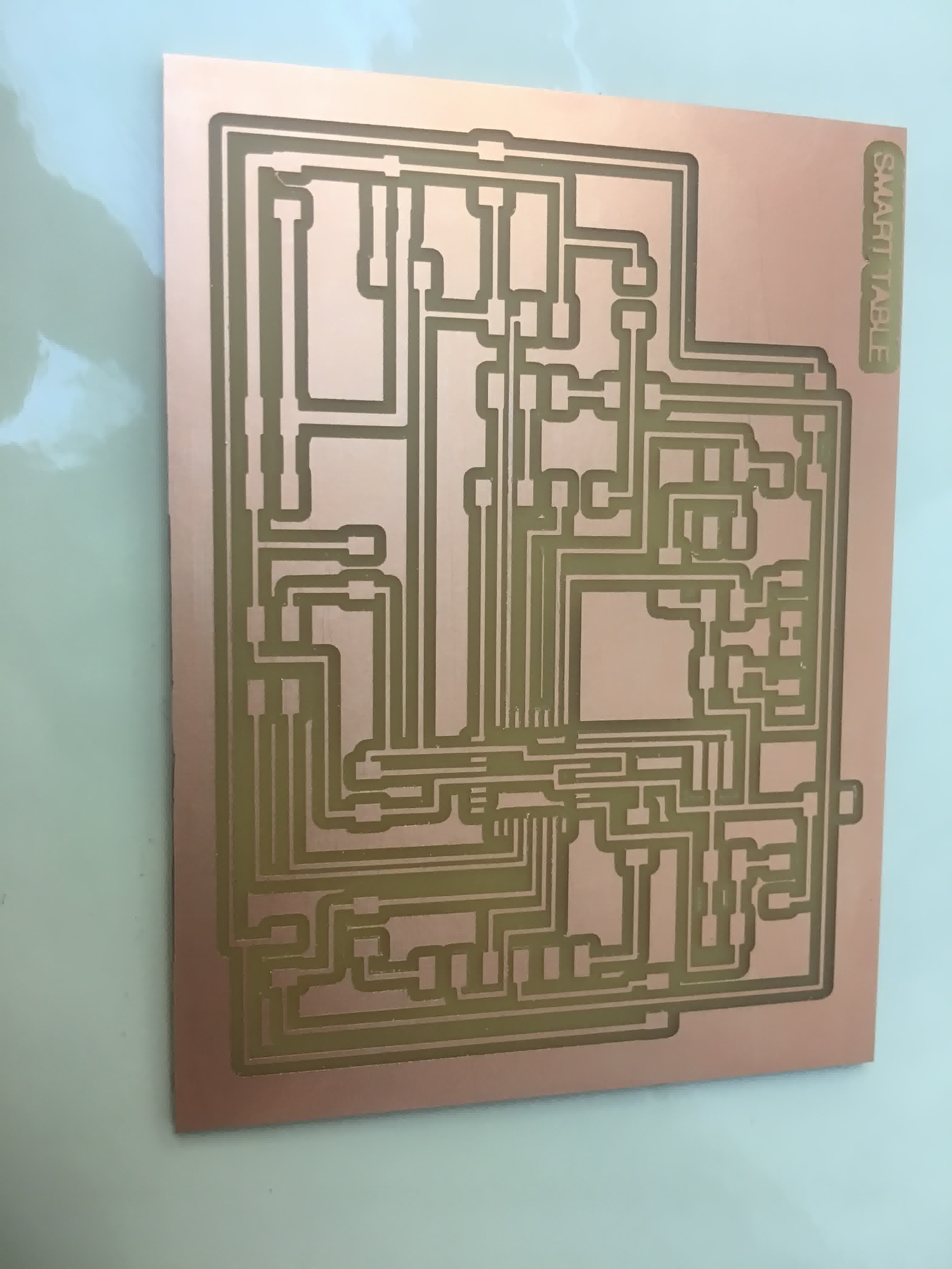
Here is my final routing after I got things right!! Long nights..

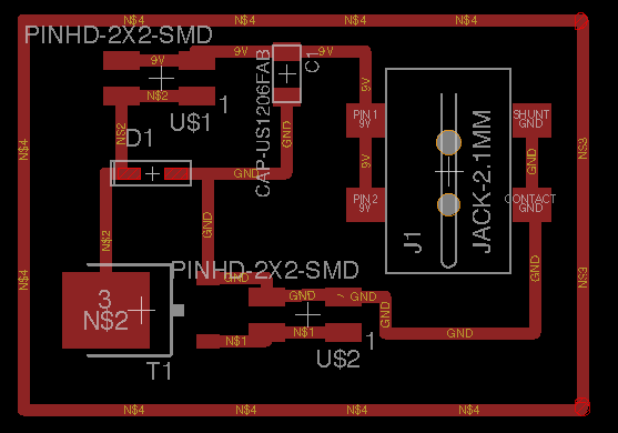
I also made a MOSFET board to keep the high power supply away from everything else, so that if something burns out, I only have to make this board again, and not have to mill and solder everything else.
Smart!!

I also made a button board so that I could interface it with the table easily.
My next step was obviously to mill everything and solder the components!
Electronics Production
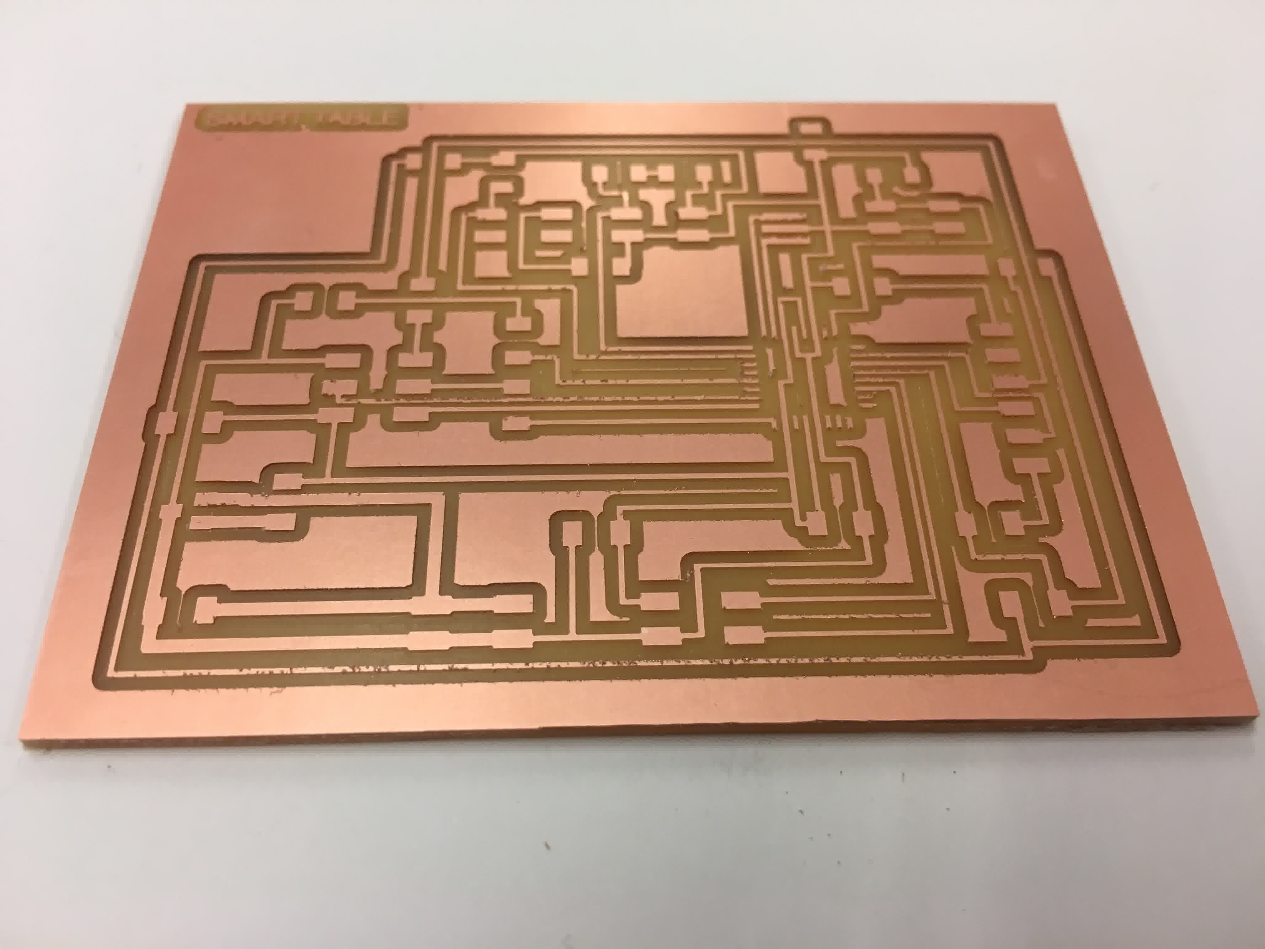
The first board I milled didn't turn out so great, because the sacrificial table on the machine was uneven, and the board came out with different depths of traces.

My next two attempts came out great, and here's a look at the final products. The MOSFET board also came out fine.


Then I started soldering.. It was really hard to solder the Atmega328 given how small the traces were.. and we didnt have lower than 20 gauge soldering wire in the shop. So, I focused and focused to make sure I get this right.. I tried different techniques. What worked in the end was to very slightly touch the solder at the intersection of the solder tip and the microcontroller pin and pull back immediately.

So now, we have the two soldered boards ready to go!! The button board didn't work so well because the holes were tool big to hold the vias. So, I ll have to redesign and nill that again.
Just when I got home after the long day, it was almost 2 AM, and I realized that my board has an LCD display, a button, a heating element, but oops - in all of this crazy routing drama with Eagle, I completely forgot to add a temperature sensor input. There goes my week long's work! Now back to Eagle to add that additional sensor. I am actually also thinking of adding an Rx and Tx line, just in case I want to interface something later..
I then redesgined the board based on my conversation with Sam. I added an FTDI header, a temperature sensor break-out, and also an LED for troubleshooting easily. I also changed the design of my MOSFET board. Made it a little simpler, remvoed a couple diodes per Sam's suggestions. And, added a pull-down resistor on the main board on the MOSFET line.

Interface Programming and Communication
The next thing I did was to test each part of my electronics capability for the table:

This was my first time working with Atmega328p boards. I first started with burning the bootloader on to my board using the Arduino IDE interface and the Atmel_ice ISP first and then switched to the usbtiny device as the programmer. Before being successful I recieved a few errors, all indicating that the board was not found. Finally I picked the Aruidno Pro Mini for the board type and the bootloader worked!

Next, I used I2C protocol to communicate with the LCD display.. I was able to get the hello world program to work.. Yay!!

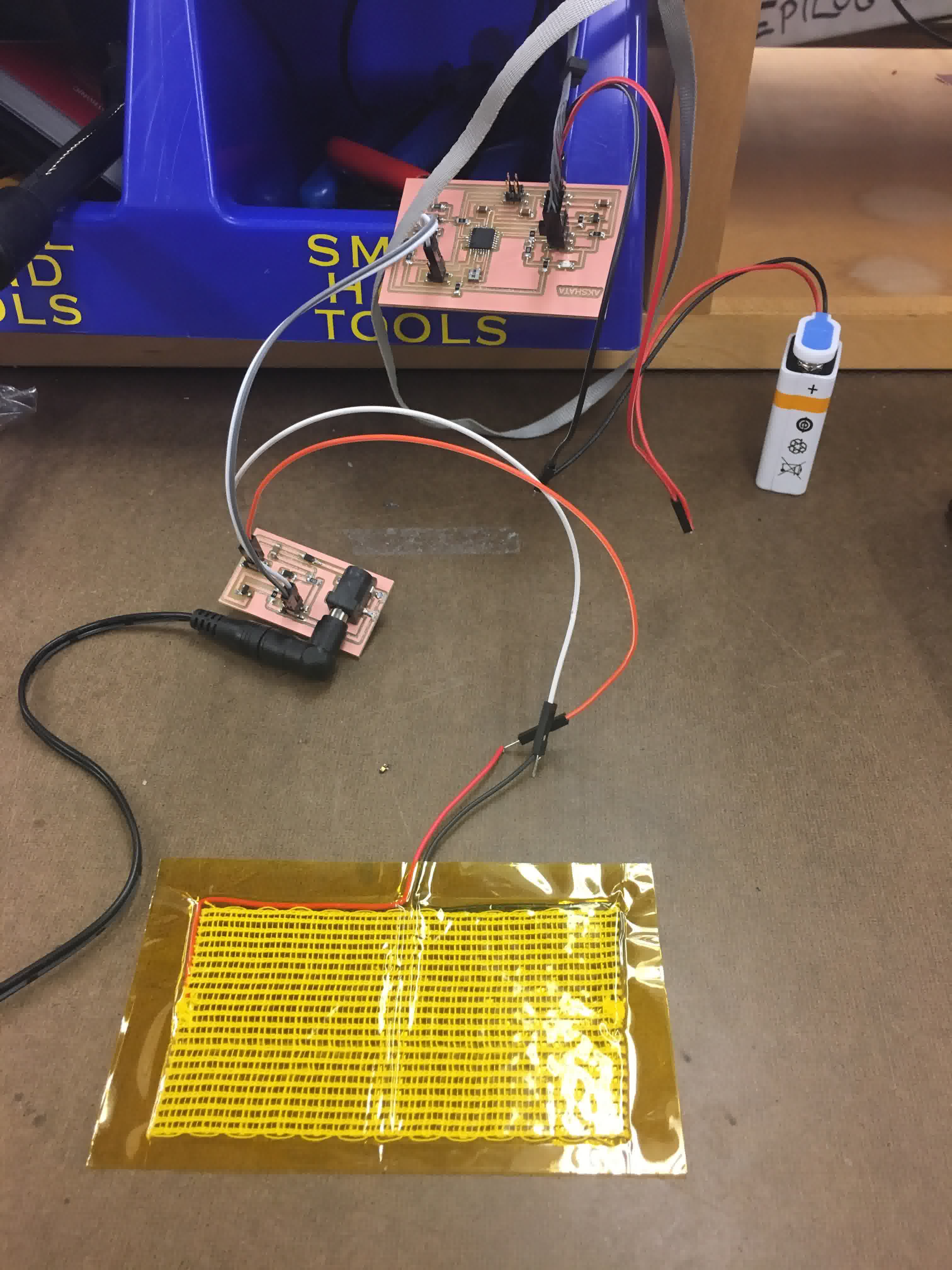
Next, I hooked up the heating pad to the MOSFET board which was connected to the main board and also the wall output power supply through an adapter. The adapter could be adjusted to voltages between 5 and 12 V. And, had 5 different options to choose from. I first tried 5 V and it got the heating pad warm. I wasn't convinced. So, I changed the voltage setting to 9V and tried again. This time I burned the MOSFET. Looks like either the MOSFET is getting too hot (because I have no heatsink) or the diode exceeding it's current carrying capacity. The diode is only rated for 1A; at 9V the heating pad is pulling ~1.6A. I replaced the MOSFET and this time, I tried 7.5V. And, tested it for ~2 hours, and it was great! The problem I had was getting the MOSFET to respond to the 5V signal. I talked to Sam who suggested that the diode could be causing the problem. Si, I redesigned the board, removed the diodes and tried again. After a lot of troubleshooting, I got it to work! Thanks to Sam and Amanda for helping with troubleshooting this part of the board. It was quite challenging to figure out why the MOSFET wouldn't respond to signals, and stay open at all times even without a 5V signal.
 Similarly, I was able to test out the temperature sensor and display the temperature on the LCD dispplay.. Success!
Then, it was time to integrate everything and code for the whole project.
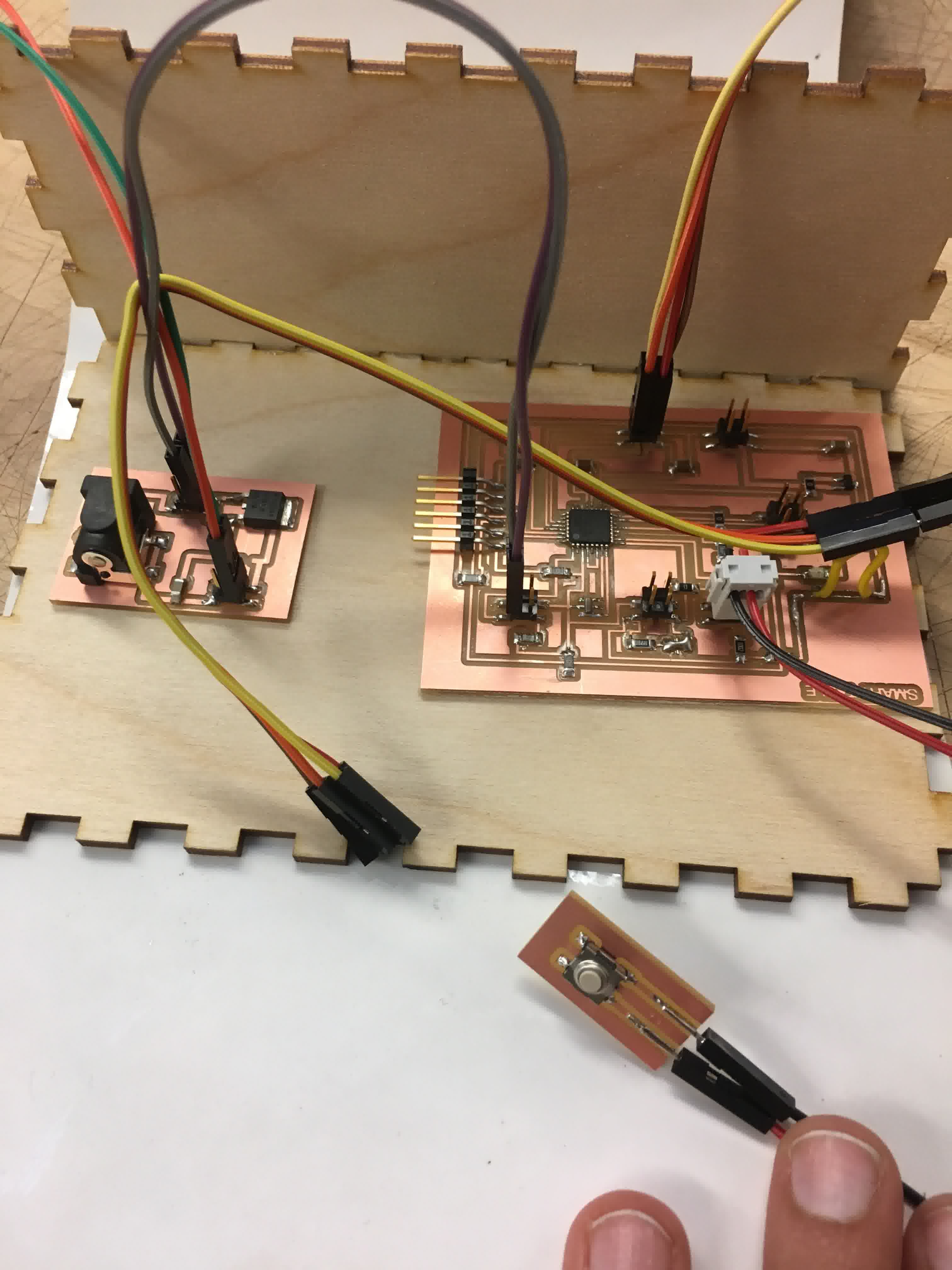
While coding, I wanted the button to toggle, and turn everything on when pressed, and turn everything off when pressed again. I also wanted to input the temperature control part where I could cut off a supply if the temperature reached a certain level. Of course, I looked at PID controllers and codes, and decided to implement it, if I had time in the end. For now, a simpler program should do, as long as I can get everything working together. So, here's the code that finally worked. I tried several other things before this, because the button wouldn't respond immediately and would take several presses before turning off.. I used debounce to make sure that wasn't the program. I checked and checked all my libraries to make sure I wasn't adding any wait times anywhere. I played around a lot with if and while loops, but nothing changed the response. Then, in the end switching to a capacitive touchpad which gave the fastest response.. I was super happy with the result!


Here's some of the code I wrote for my system..
System Integration
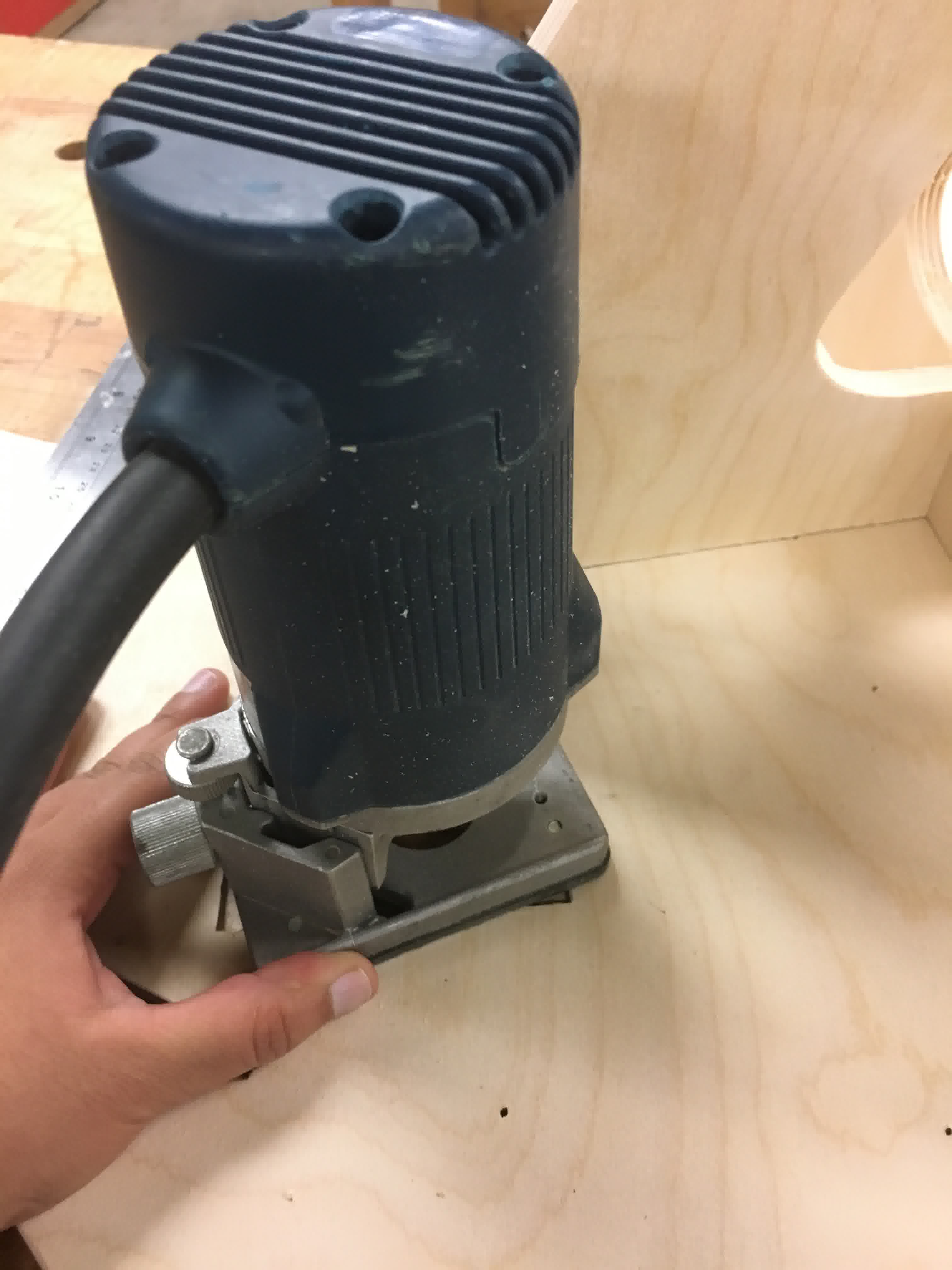
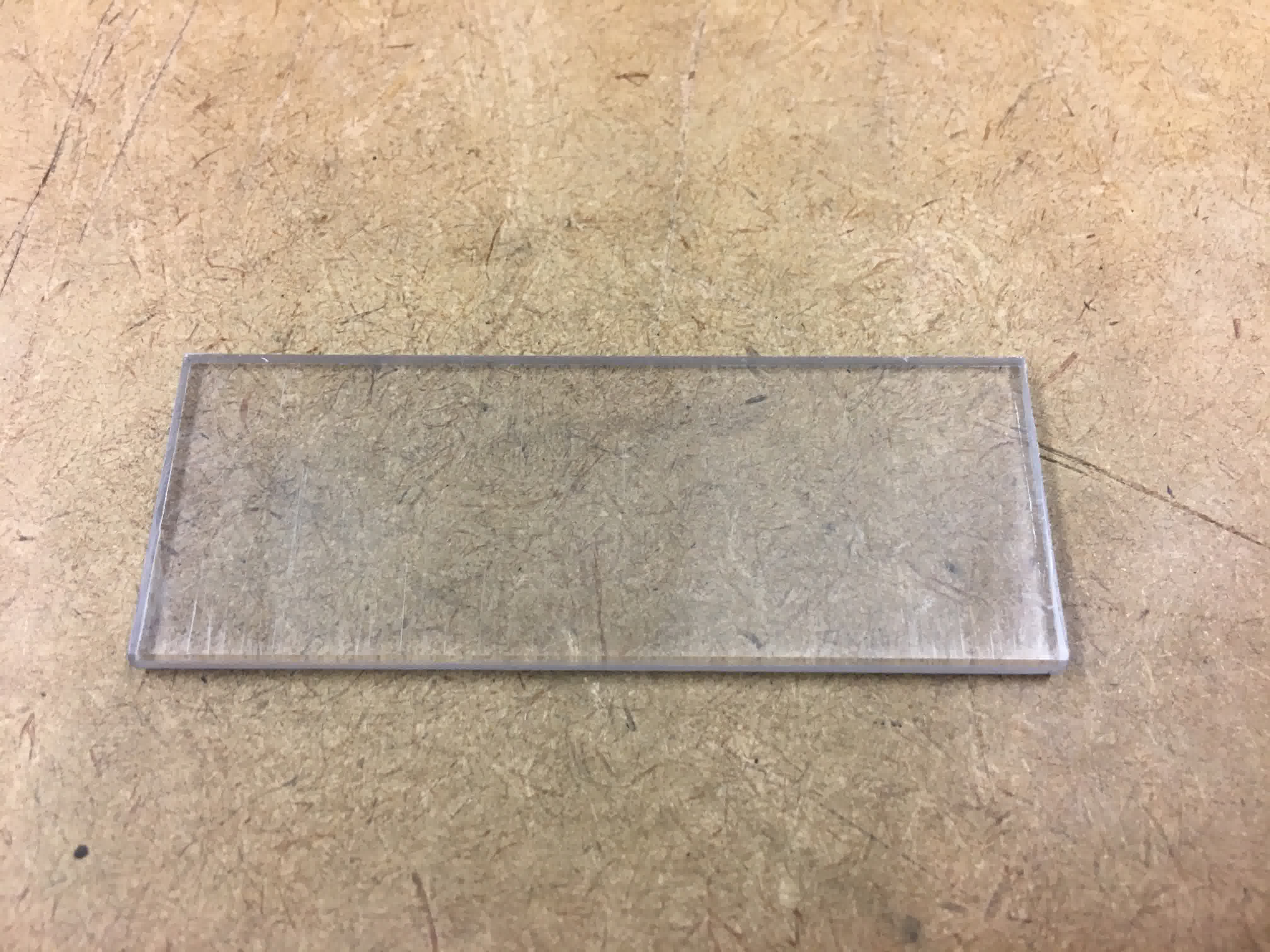
Next comes the system integration part. This was the most important part given that I had everything working separately. I had kept several days for system integration, and had thought about all along the way, tweaking and making changes as and when I went ahead with fabrication. I had cut out the pockets and used a hand router to make changes to pocket sizes, and measured and remeasured them until they fit. Added a plexi glass window for the display.
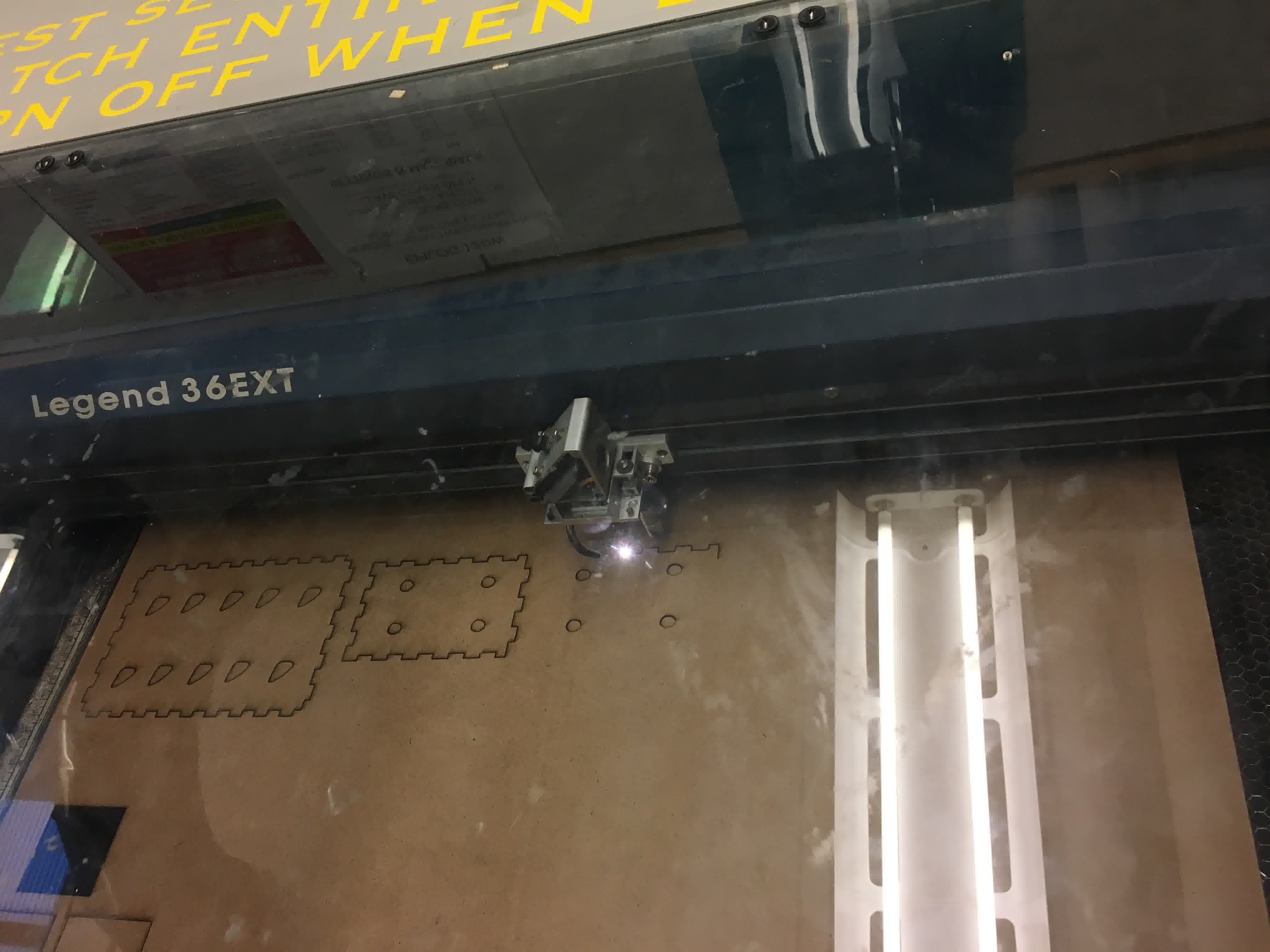
I also made a button using the 3D printer, and a box using the laser cutter for the boards! I didn't end up using this in the end..

I also cut a plexiglass cover for the LCD display..
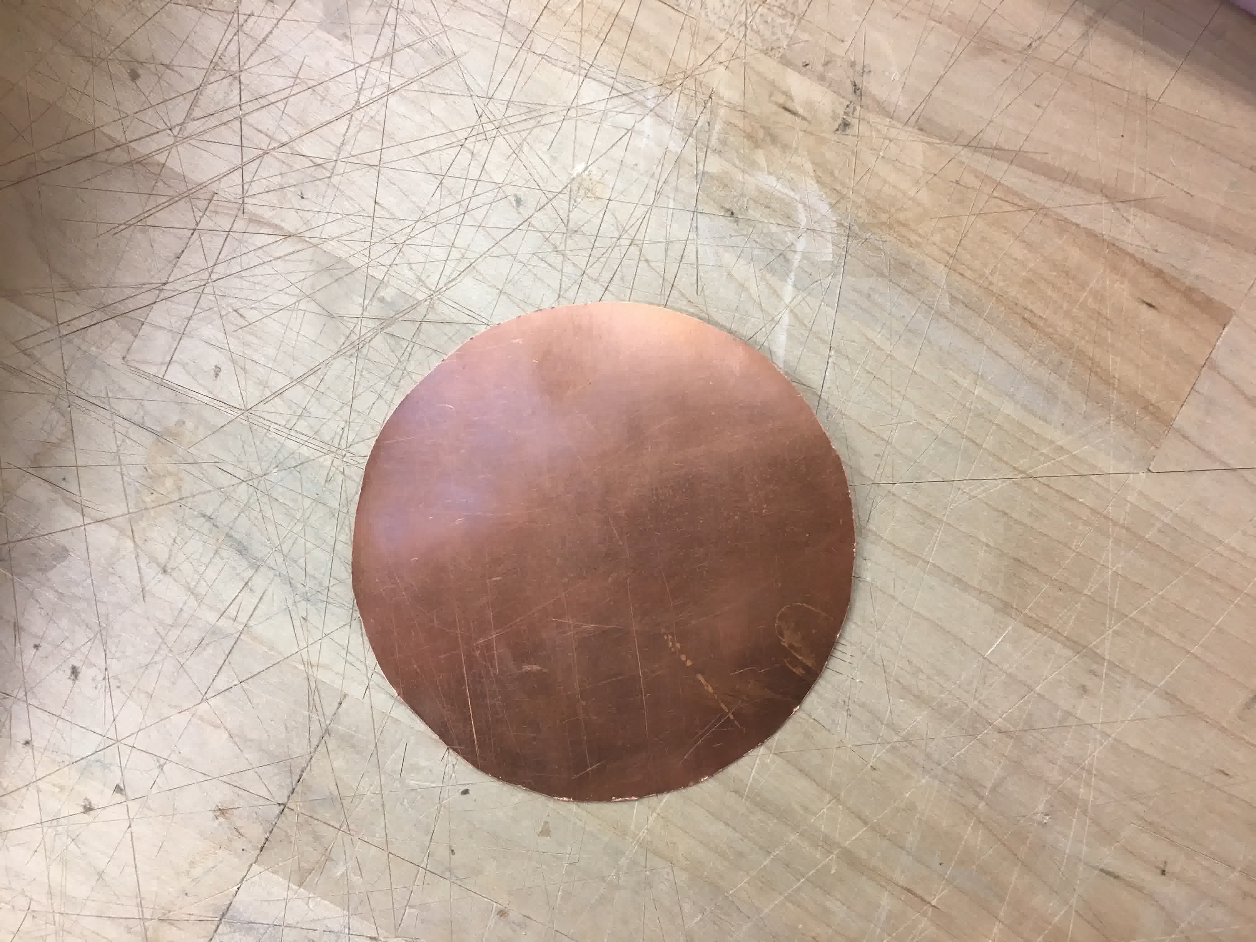
I then made the sheet metal heater in the arch shop.. It was a lot of fun cutting out the piece with a hand cutter..
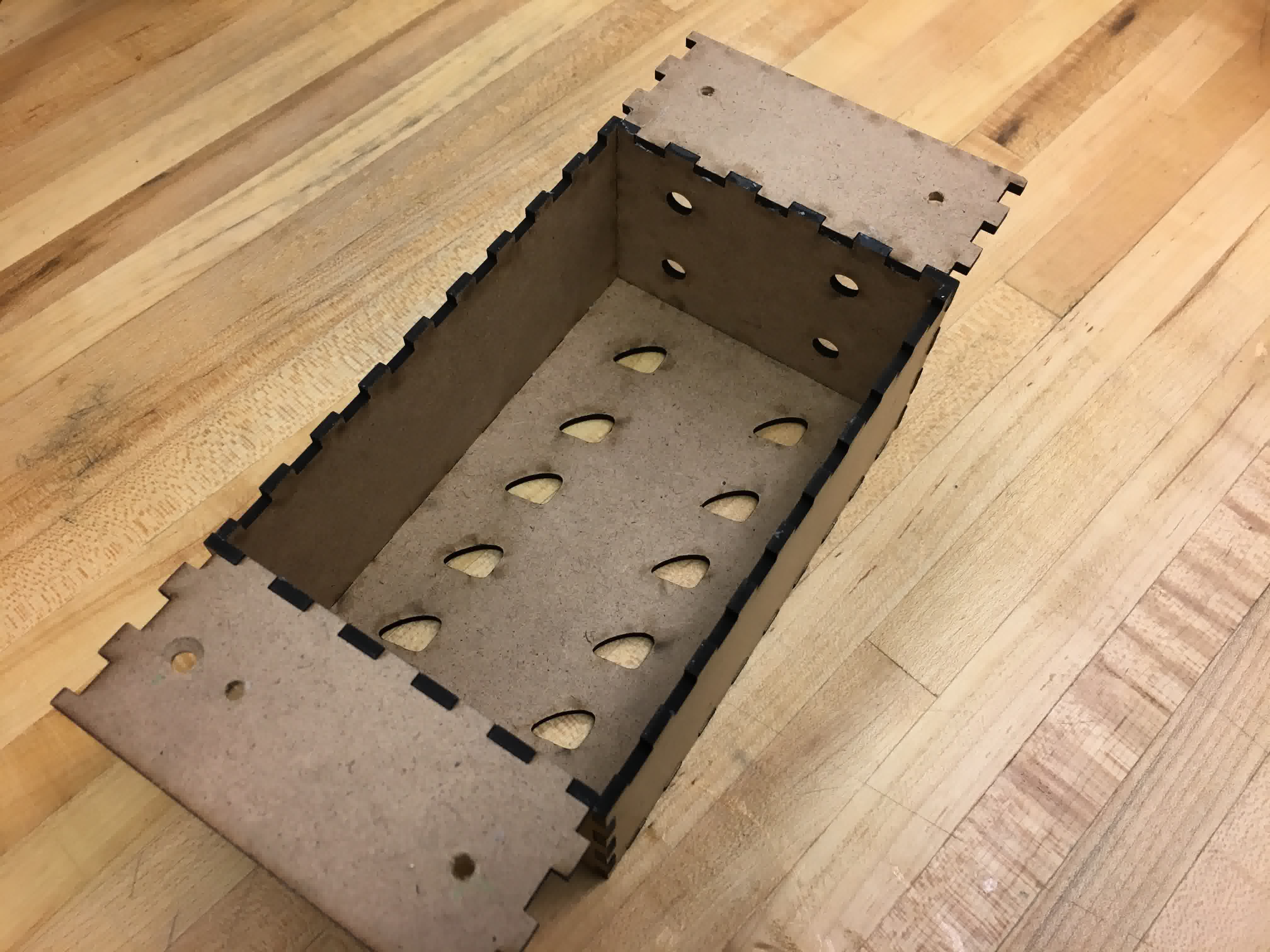
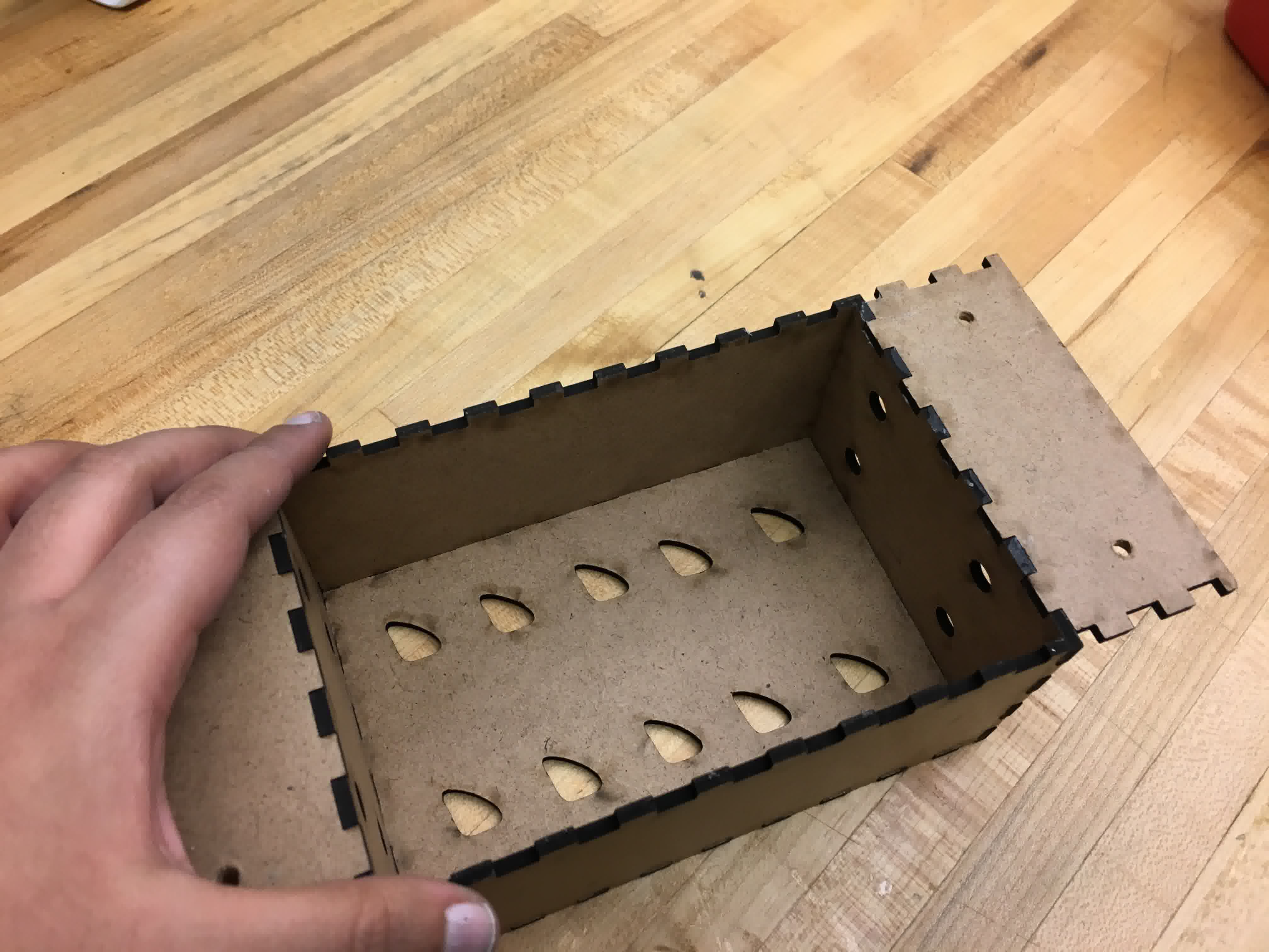
I also designed a nice box to fit all my electronics in. I designed it to have plenty of pockets for air circulation so that the electronics don't heat up a lot.
Then, my task was to assemble the electronics with the table.. I have a video of the making of the table in the beginning of this page.
I did some testing as well.. Below are the pictures:
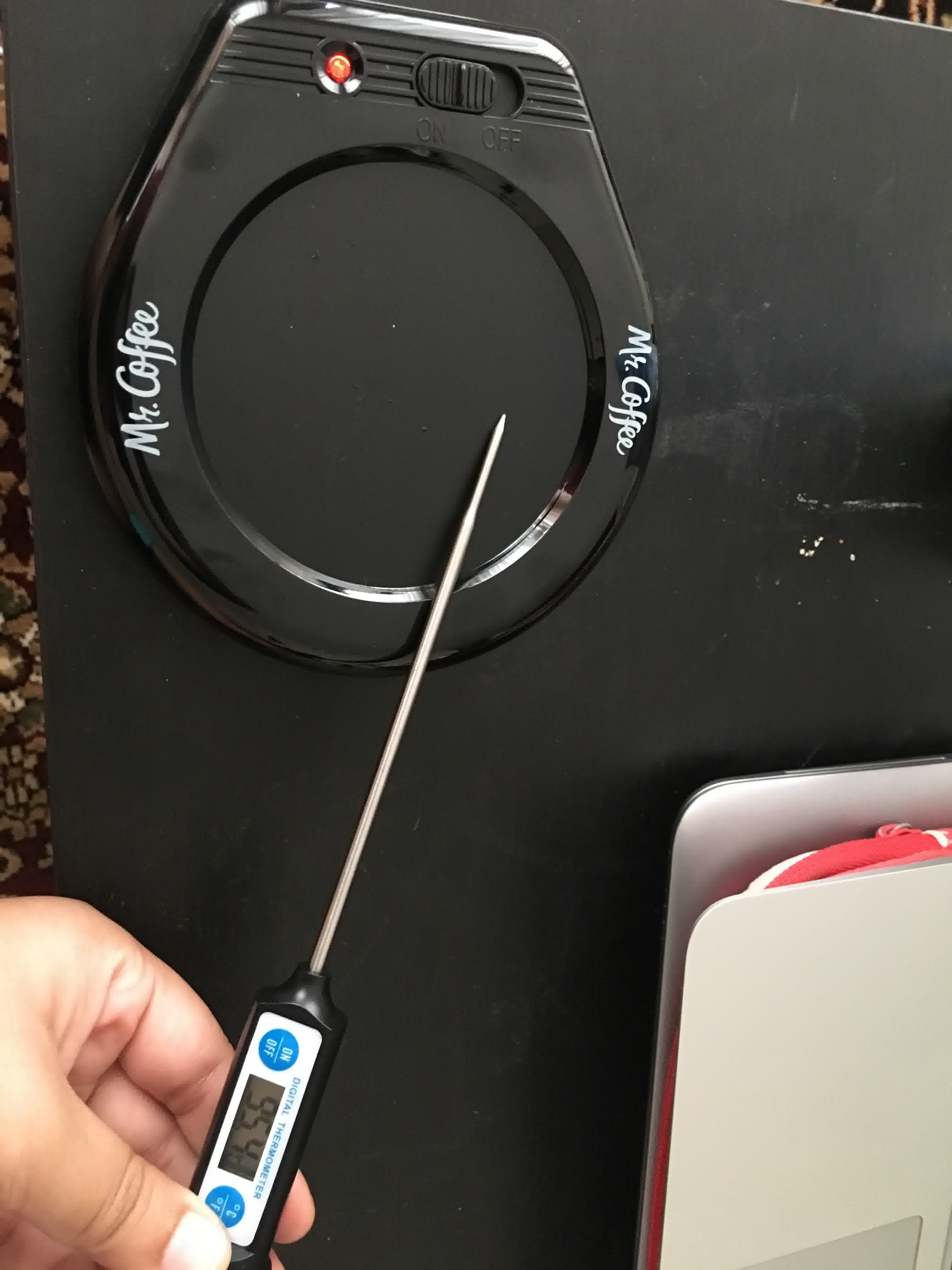
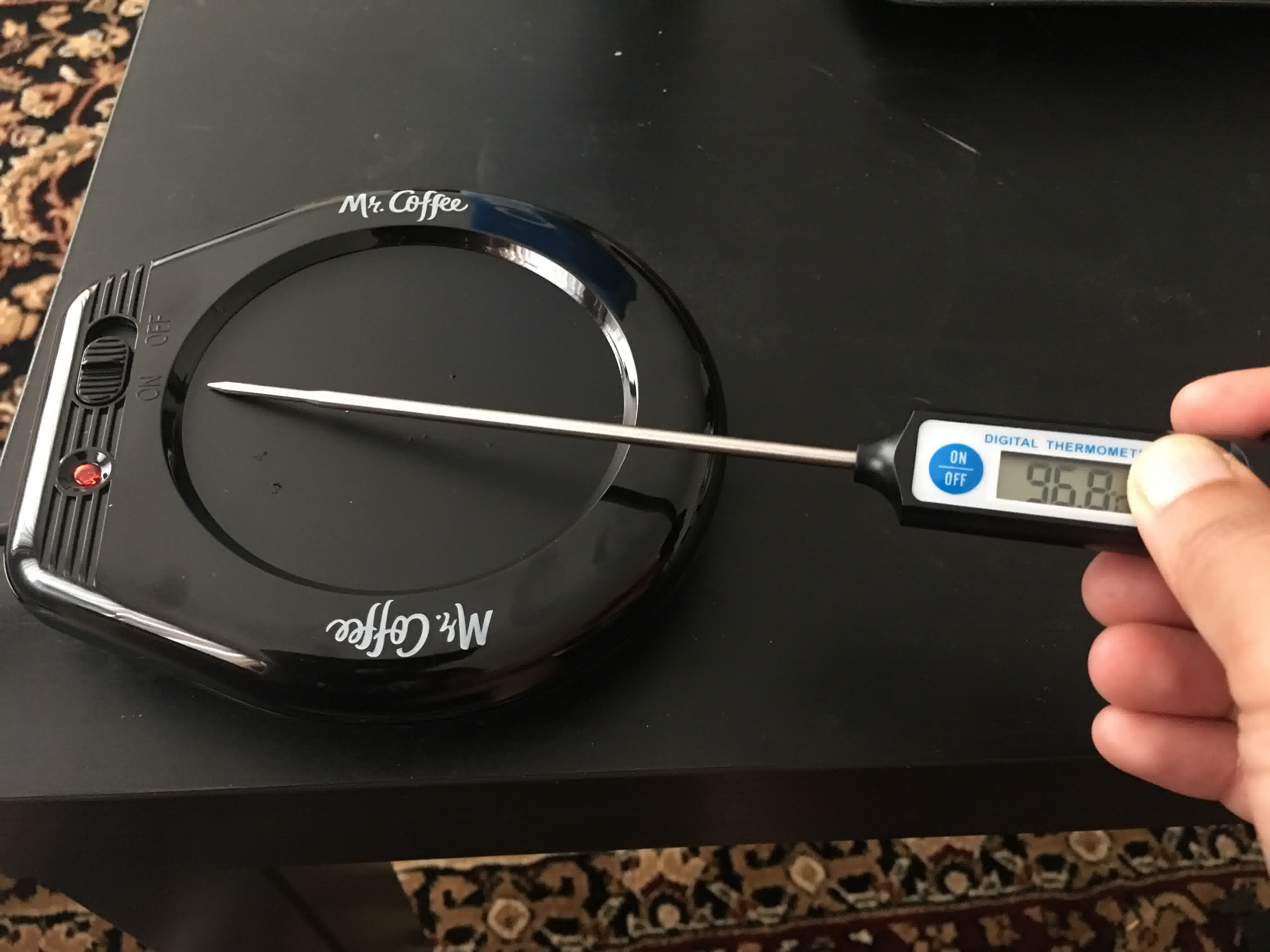
I checked with a digital thermometer that the temperature measured by the sensor under the heating element was the same as the top of sheet metal piece. So, the conductivity was great!

The power supply adapter I chose had several voltage settings: 5V, 6V, 7.5V, 9V and 12V. The documentation for the heating pad indicated that it can be operated between 5-12V and would draw between 0.5-2A of current. The MOSFET I picked was rated for 50V and 16A, and I checked the graph of voltage vs. current in the datasheet to make sure it would be okay to operate at these voltages. The maximum temperature reached at 12V was 100 degrees C, which would be perfect to keep coffee/tea hot for a very long time!!

Components used and where they came from
1. Table - 1/2-inch Russian birch - half sheet - from N51 shop - $27.5
2. Enclosure - Laser cut from scrap piece of plywood in the arch shop - recycle and reuse!!
3. Electronics Boards and all components on them - total of $15 from Digikey
4. Kapton flexible heater - Amazon - $3
5. Sheet metal piece for heating surface - scrap from N51 shop
6. Temperature sensor - Amazon - $2
7. LCD display - Amazon - $10
7. Button was 3D printed, but then I switched to laser-cut capacitive sensor
8. Wall adapter 5-12 V, 2 A - $10
Total cost = $69What questions were answered?
- How easily can we integrate smart capabilties with furniture design? - What are the design considerations when we're dealing with heat and wood? - How do we interface between multiple sensors and actuators (in this case, the touch sensor, temp. sensor, heating element and the LCD display).
How was it evaluated?
I think the project was hugely successful given that this class was the first time ever I did - electronics design and production, interface programming, communications, CNC milling, laser cutting and 3D printing. I learned a lot of skills and was able to apply towards a neat final project, which was well outside of my area of expertise (aerospace engineering to furniture design!!) .. I am proud of what I have accomplished in one semester!
What are the implications?
This project demonstrates the feasiblity of a smart table. Next steps would include adding PID control to ensure more accurate control of temperature. I would also experiment with different power supplies and switching circuits, and increase the power consumption. In addition to warming coffee, we can make tea as well! In terms of interface programming, I would add a menu to the display and let the user choose a temperature setting. This would make the table more interactive!