This week, I milled and soldered, and got the USBtiny working! For the milling process, I used the SRM-20 machine in the arch shop, along with the Mods software. It is fairly easy to set up. Open the Mods server and software, and the SRM-20 machine software.
There are two files. One is the traces that need to be milled with the 1/64 end mill. The other image is the outline that needs the 1/32 end mill.
Once we upload the png file, we click on calculate that shows all the tool paths. We confirm that it is exactly what we want, and then click on Send file to machine.
Of course, we have to make sure that the tip of the end mill is touching the surface of the board.
I followed Brian's
tutorial for this week's assignment. The tutorial is thorough, and is super helpful for a beginner.

I started milling my first board on the SRM-20 in the arch shop. The set up very easy. Open the mods server, open the mods program. Open the SRM-20 machine. Upload the png image and select the 1/64" end mill for the traces, and 1/32" end mill for the outline cut. Then, click on calculate that calculates the tool paths. Verify that the tool paths are doing exactly what want. Then, click on send file to printer. Before we send file to the printer we have to set up the tool to be touching into the surface on the board at the exact point where we want the milling process to begin.
As soon as I started milling my traces, I realized that the end mill was slightly above the surface and hence it did not have enough depth in the first few offsets.
You can notice that the end mill is barely cutting into the board in these two pictures.
On my second try, I made sure to bring the end mill down and touch the surface firmly. It went great, until the very end.. And, suddenly something went wrong, and the board started wobbling. It turns out that the surface on which I had fixed the board wasn't clean enough and had some dust from previous mills. So, towards the end, the board wasn't strongly fixed to the surface, and hence started to move. To avoid this, we should always ensure that the mounting surface is clean, and we use sufficient tape to hold down the board tightly.
The dust from previous mills stuck on the tape and caused the board to move when I was milling with the 1/32 end mill..
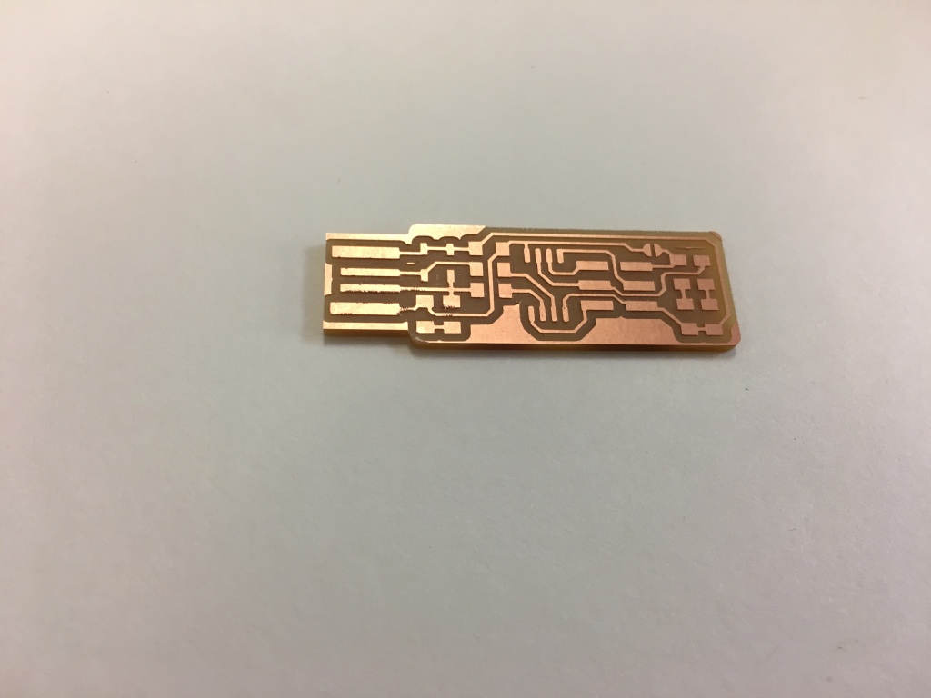
Finally, on my third try, everything went perfectly well, and there I had an awesome-looking board ready to solder!!!
Let's take another look at the board, and verify that all the traces came out fine, and there are no errors.
The next step was to gather all the electronic components that I needed for the soldering process, and arrange them so that I don't end up getting confused in the middle of the process. I also fixed the board with a double sided tape on to the paper to make sure it stayed in place while I soldered.
As a first step, I soldered on my failed boards to practice and refine my technique. And, then I started to solder on the good board. And, here's what I produced at the end of the quick soldering process which took about an hour. It should probably take half the time with sufficient practice!
I then took a multimeter and checked to make sure that all the grounds were connected and there was no shorting with the positive voltage lines.
Here's the final board with all the components soldered.
I followed Brian's tutorial to flash the fts_firmware program, set fuses, and then reset disable which disables our ability to load a program using the AVRISP.
Now, we remove the solder bridge, and there we have our USBTiny programmer!