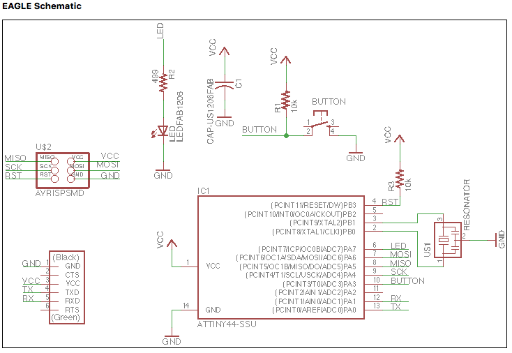
Schematic and Board Design using Eagle
This week's assignment was to design and produce our own board. Two features we had to add were an LED and a button. This was my first time working in Eagle. Jonah gave a quick overview of the software, and the tools we needed to know. I then went ahead and played around a bit before successfully making the schematic, and the board. Some things to remember are: Check the design rules to make sure that the clearance between pads and between all components is at least 16 mils. The width of the traces that I used was 16, but 12 could work as well. There is a check button on the design rules window. Make sure to run the check when you're done making the board to confirm that there are no overlaps or low clearance lines. For the schematic, I would suggest running ERC to check for inconsistencies befor creating the board, so that all the work from the schematic actually get carried over to the board.
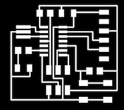
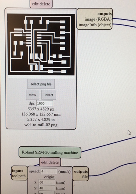
The production itself was straight forward, given that we had used the milling machine two weeks back. I uploaded the png image on the mods server, and then milled the traces using the 1/64" end mill, followed by cutting the outline using the 1/32" end mill.
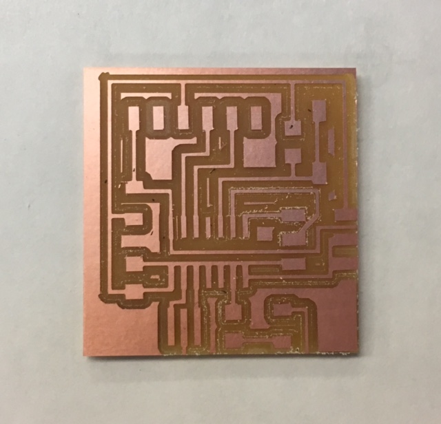
As I started milling my board, I noticed that the outline ended up going over the edge of the board. So, it cut some of my traces out.
On my second try, I made sure to increase the distance between the edges and the outline.
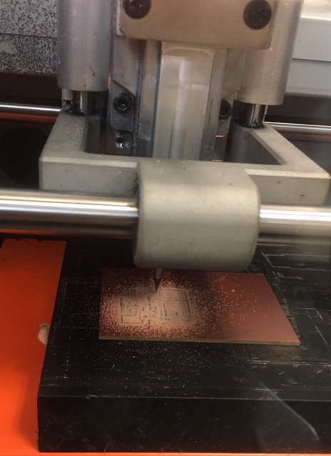
Here is a picture from my first failed attempt with some of the traces on the edge cut out..!
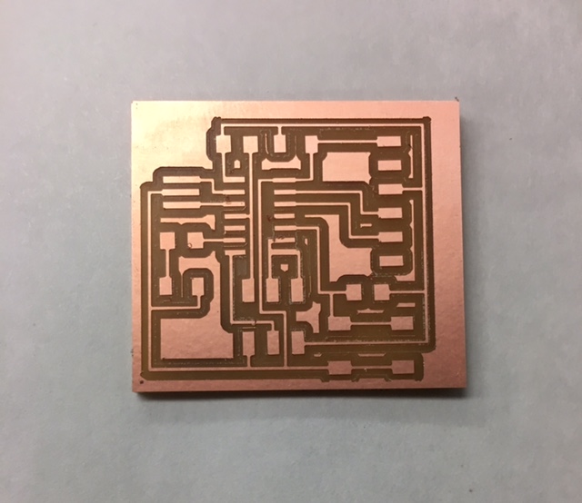
So, I went back into Eagle and made some changes to the outline to make sure this time I don't cut the edges out..
Finally, on my second try, everything went perfectly well, and voila, I had an awesome-looking board ready to solder!!!
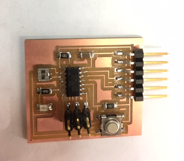
The next step was to gather all the electronic components that I needed for the soldering process, and arrange them so that I don't end up getting confused in the middle of the process. I also fixed the board with a double sided tape on to the paper to make sure it stayed in place while I soldered.
The next step is to program the board and check if it works, which I did in the Embedded Programming week.