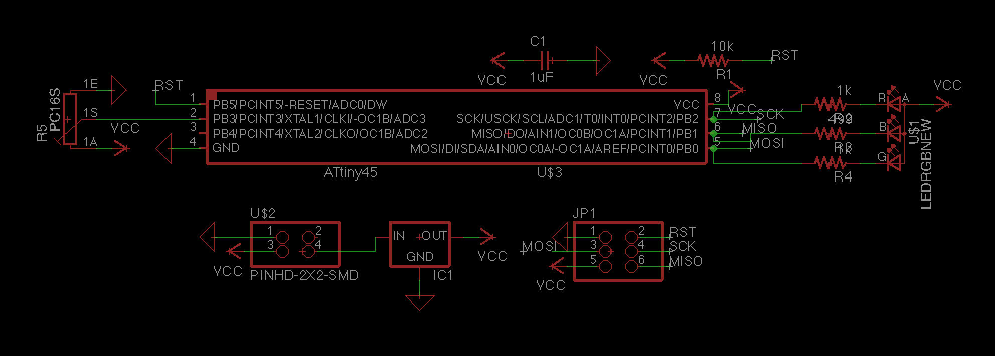
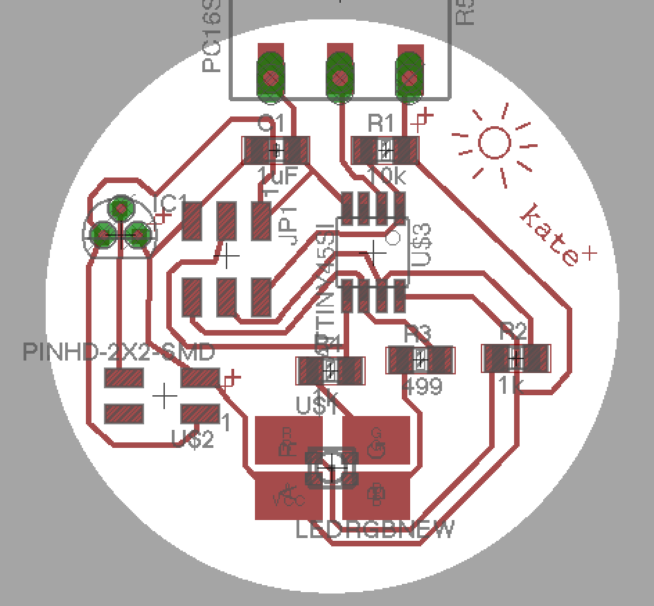
This week in how to break (almost) anything, we had to attach an output device to a board. Seems simple, no? But of course, there were all sorts of new and uncharted ways to go horribly wrong. Having attempted an rgb LED with a button during the last electronics week, I decided I would try to up my game a bit and use a potentiometer to control color. I decided to base it off of Neil's rgb board, which seemed like a good idea at the time, but later proved to cause some trouble. I set up the schematic in eagle based on Neil's board layout, but I wasn't really sure how a 2x2 header provided power, so I messed that up a bit.
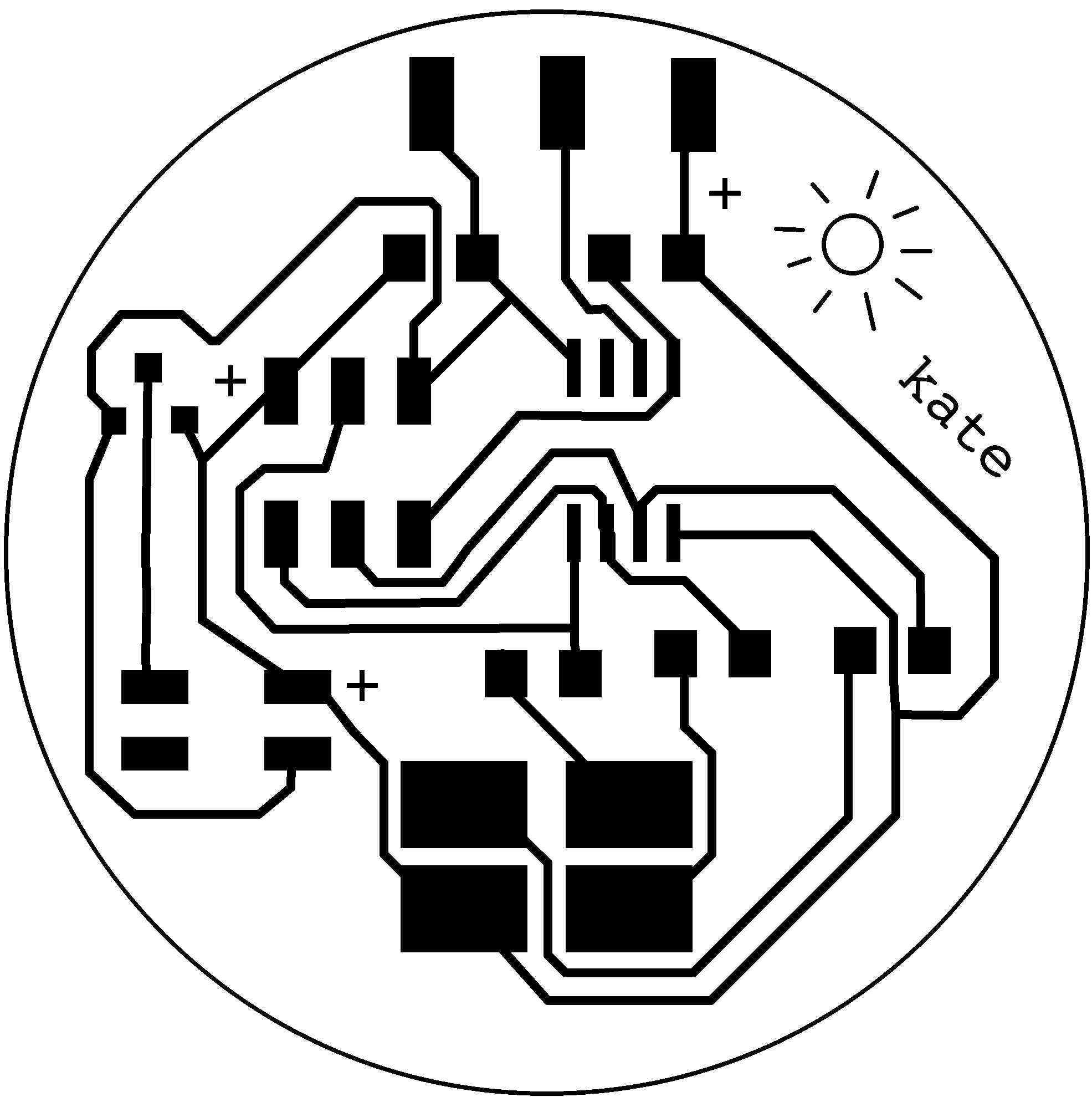
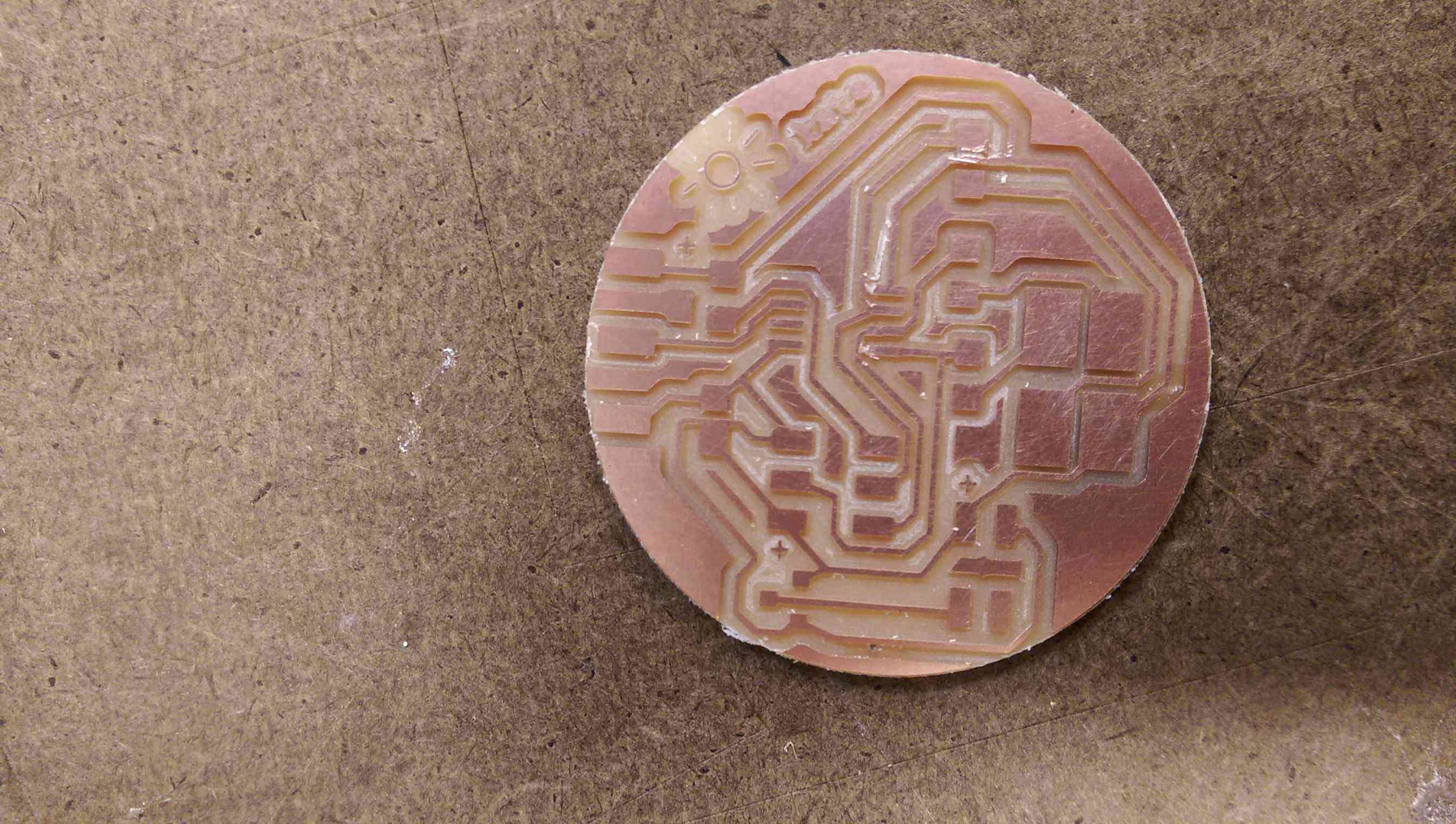
Unfortunately, I didn't realize my mistake and went ahead and milled the board. Other than forgetting to set the dpi in mods (which I quickly fixed after it milled a really big line), the milling went smoothly. That part, at least, I pretty much have down. The soldering also went pretty well, though I had to use a knife to separate some traces that were too close together (I also forgot to DRC after manually editing the traces) and to make a bit of extra space to attach the giant potentiometer. Designing in Eagle is still a bit painful, but actually making the board has finally become fun and reasonably predictable.
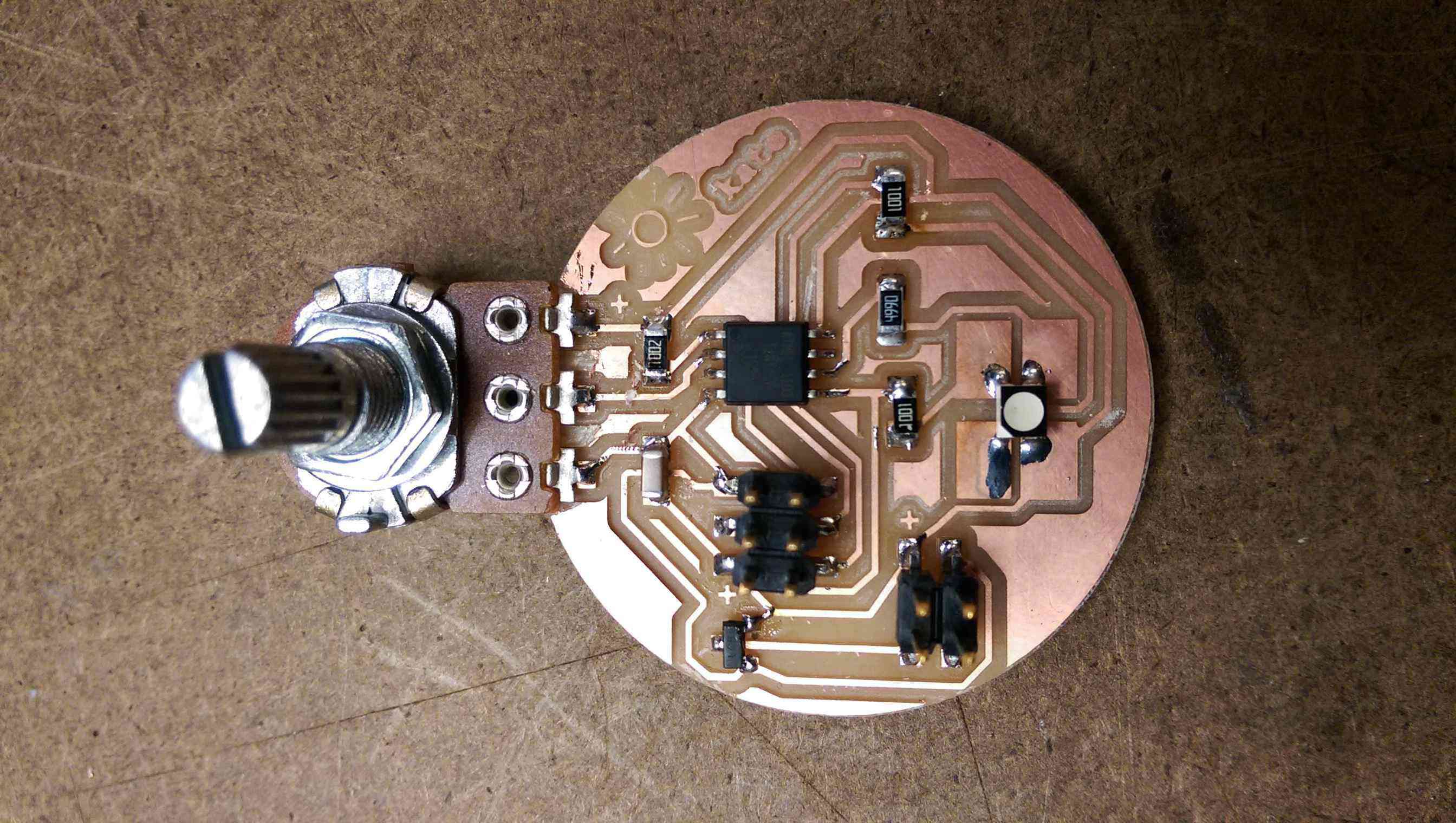
After I finished soldering, I looked back at Neil's board to figure out what on earth this 4-pin cable was that I was supposed to get power from. Mainly, I was just confused as to why he needed four pins when power supplies only have two: power and ground (though at this point I was starting to question that). Upon closer inspection, I realized that he had connected two of the pins and neglected one, making it really just power and ground, but they were next to each other. I had failed to connect the pins, so my power and ground were diagonal from each other. Oops.
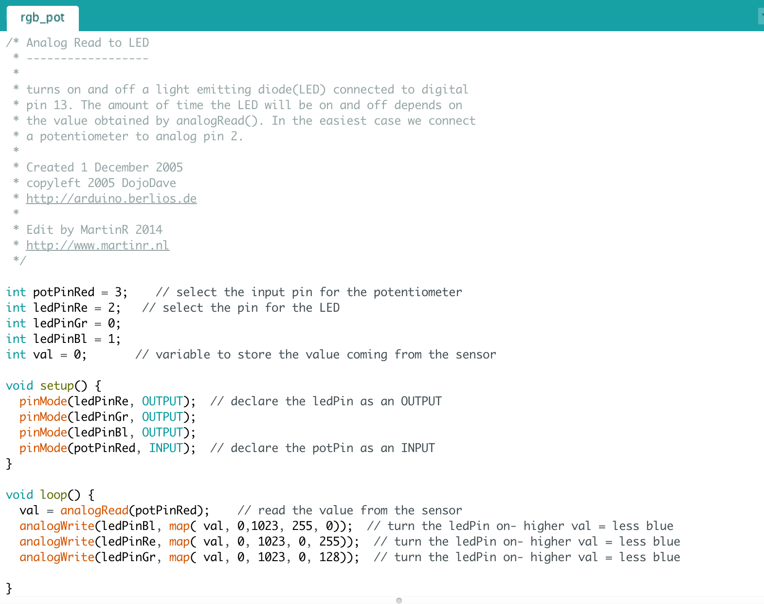
With a bit of scraping and a quick solder jumper, I fixed it so that power was going from one pin of the header to the correct pin on the regulator and ground was going from another pin on the header to the middle of the regulator. Unfortunately, designing and debugging this much took some time, so I didn't have much time left for software debugging. I spent a lot of time searching the internet trying to figure out how to correctly set up a potentiometer in C and map the input values to the correct output values on the rgb LED, but I was not confident that anything I tried would work, and I was a bit terrified of breaking yet another board, so I turned to the Arduino IDE and it's super helpful libraries instead.
After I finally managed to get back to the shop to solder the jumper, I brought the board home to program. I only had a 9V battery and clip to power it because I had messed up the pins and couldn't use whatever cord Neil had used for the model board. I don't have a soldering iron at home and electrical tape apparently doesn't stick to metal, so I duct taped the wires of the battery clip to the pins. I very carefully hooked up the board to the programmer, making sure to orient it the cord properly, plugged the programmer into the usb extension cord, which I plugged into my computer, and then I hooked up the battery. Aaaaaand nothing happened. The little red light on the programmer didn't even light up, so I knew something was very wrong.
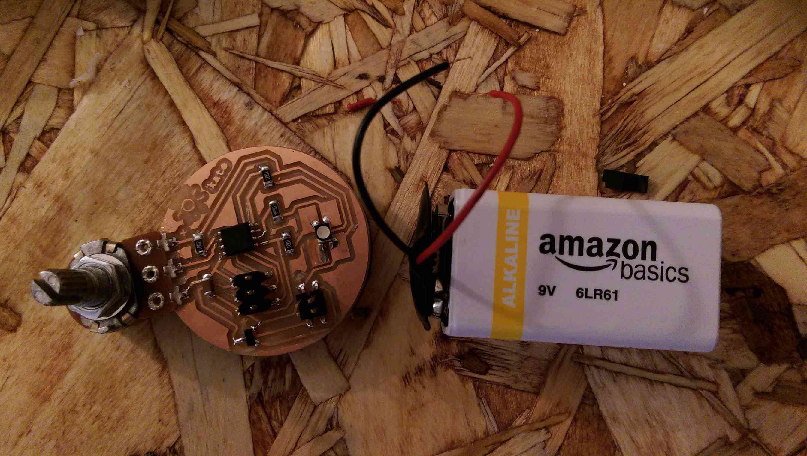
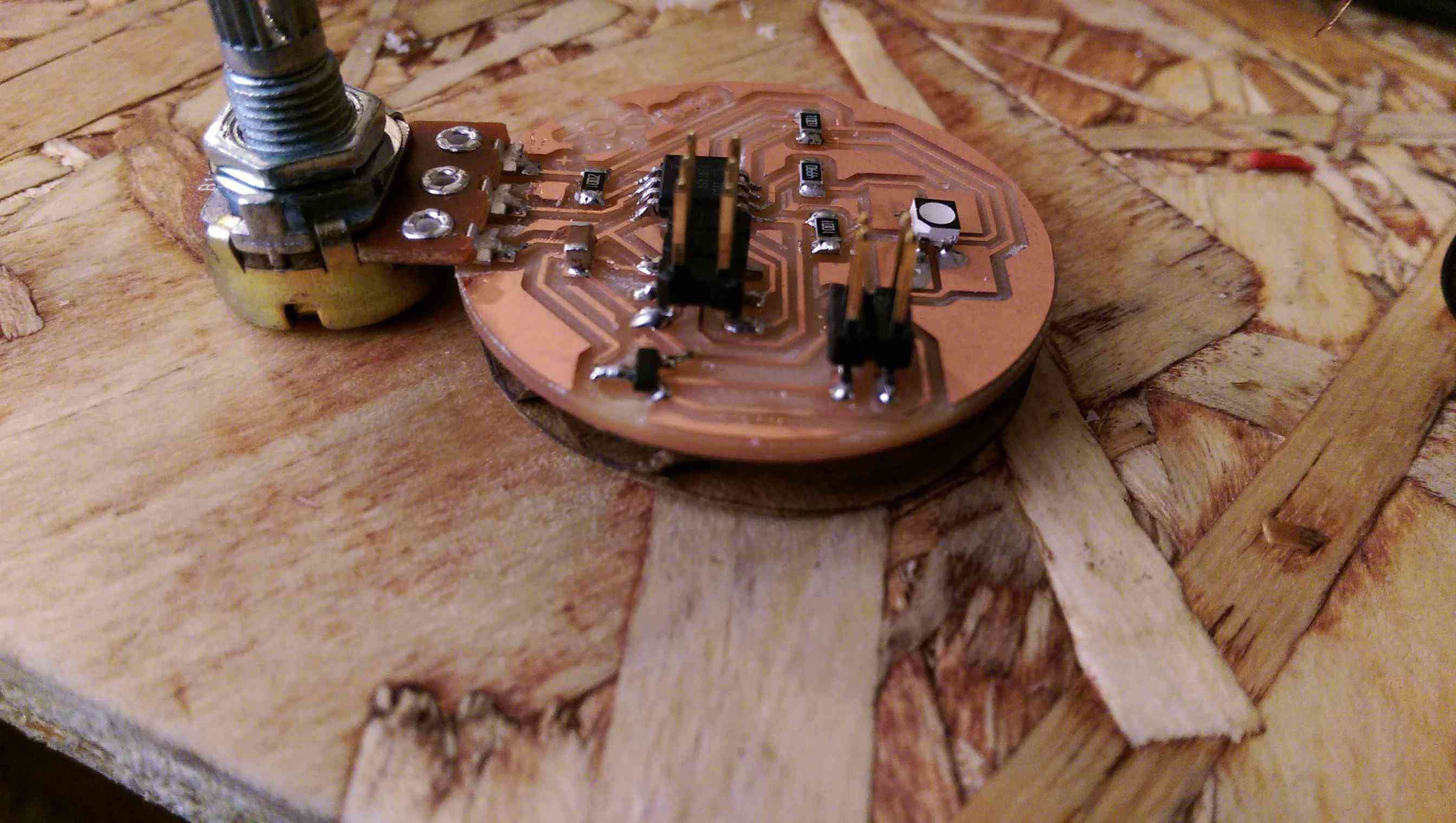
I decided to use the battery clip as a makeshift voltmeter, so I touched the wires directly to the traces going to power and ground. There was a tiny spark and the smell of burning board (which I am sad to say I now recognize) and one of the traces turned a bit brown. You can sort of see it in the image below. Based on what burnt and where the solder jumper was, I'm inclined to believe that I created a short somewhere around the voltage regulator, but I don't know for sure. Unfortunately, I'm too far from campus to fix this tonight, so I will try again tomorrow.
Update 11/18: I managed to get a similar board working properly. You can check out that shockingly cooperative RGB LED in Input Devices Week.
Unfortunately, I didn't realize my mistake and went ahead and milled the board. Other than forgetting to set the dpi in mods (which I quickly fixed after it milled a really big line), the milling went smoothly. That part, at least, I pretty much have down. The soldering also went pretty well, though I had to use a knife to separate some traces that were too close together (I also forgot to DRC after manually editing the traces) and to make a bit of extra space to attach the giant potentiometer. Designing in Eagle is still a bit painful, but actually making the board has finally become fun and reasonably predictable.
After I finished soldering, I looked back at Neil's board to figure out what on earth this 4-pin cable was that I was supposed to get power from. Mainly, I was just confused as to why he needed four pins when power supplies only have two: power and ground (though at this point I was starting to question that). Upon closer inspection, I realized that he had connected two of the pins and neglected one, making it really just power and ground, but they were next to each other. I had failed to connect the pins, so my power and ground were diagonal from each other. Oops.
With a bit of scraping and a quick solder jumper, I fixed it so that power was going from one pin of the header to the correct pin on the regulator and ground was going from another pin on the header to the middle of the regulator. Unfortunately, designing and debugging this much took some time, so I didn't have much time left for software debugging. I spent a lot of time searching the internet trying to figure out how to correctly set up a potentiometer in C and map the input values to the correct output values on the rgb LED, but I was not confident that anything I tried would work, and I was a bit terrified of breaking yet another board, so I turned to the Arduino IDE and it's super helpful libraries instead.
After I finally managed to get back to the shop to solder the jumper, I brought the board home to program. I only had a 9V battery and clip to power it because I had messed up the pins and couldn't use whatever cord Neil had used for the model board. I don't have a soldering iron at home and electrical tape apparently doesn't stick to metal, so I duct taped the wires of the battery clip to the pins. I very carefully hooked up the board to the programmer, making sure to orient it the cord properly, plugged the programmer into the usb extension cord, which I plugged into my computer, and then I hooked up the battery. Aaaaaand nothing happened. The little red light on the programmer didn't even light up, so I knew something was very wrong.
I decided to use the battery clip as a makeshift voltmeter, so I touched the wires directly to the traces going to power and ground. There was a tiny spark and the smell of burning board (which I am sad to say I now recognize) and one of the traces turned a bit brown. You can sort of see it in the image below. Based on what burnt and where the solder jumper was, I'm inclined to believe that I created a short somewhere around the voltage regulator, but I don't know for sure. Unfortunately, I'm too far from campus to fix this tonight, so I will try again tomorrow.
Update 11/18: I managed to get a similar board working properly. You can check out that shockingly cooperative RGB LED in Input Devices Week.