11.2 programming (sorta)
This was a busy week (making up for the time with pancakeBot), and I definitely didn't leave myself enough time to tackle getting ADC inputs on the nRF52 (as this is somewhat non-trivial). My initial idea was to get two light sensors to modulate the output of two servos, as a braitenberg vehicle.
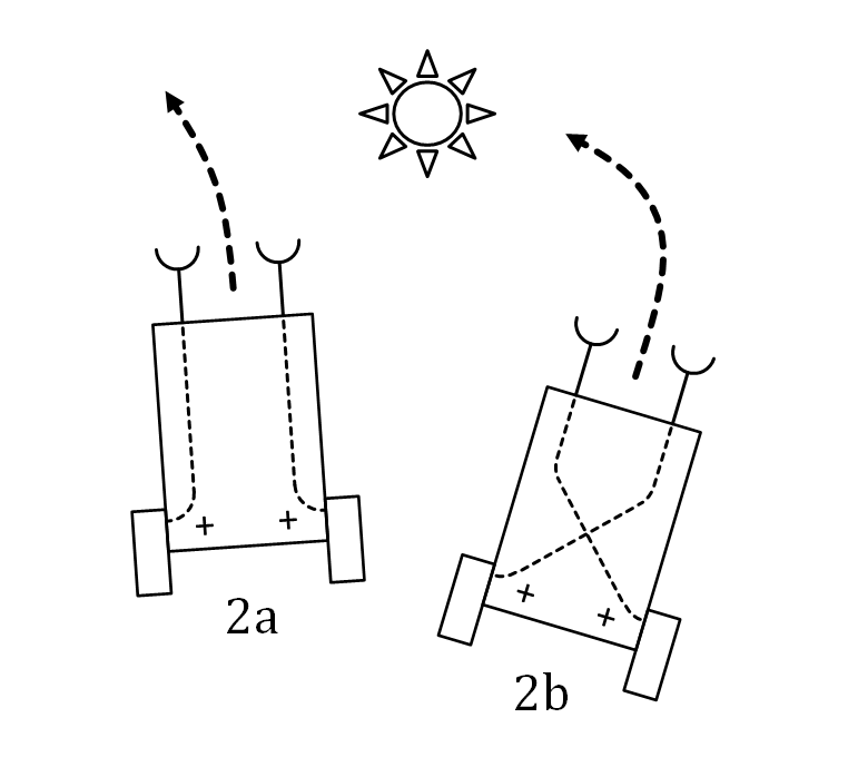
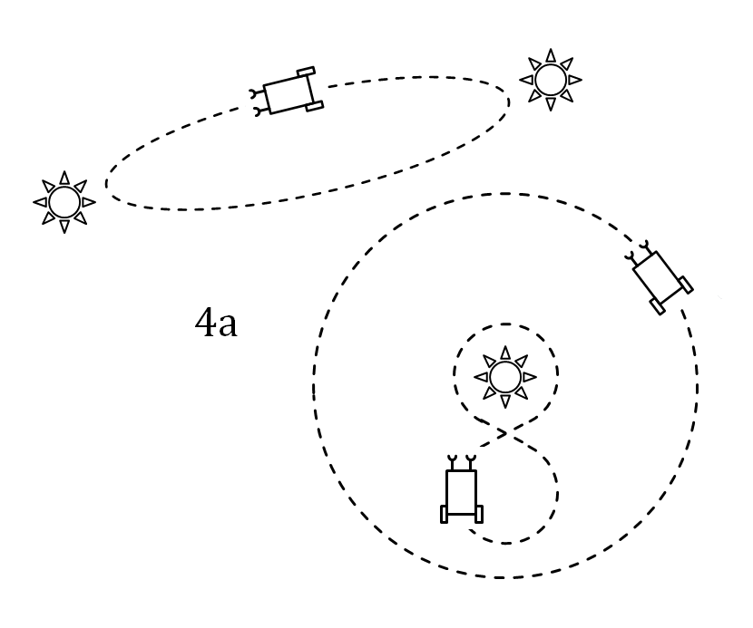 Though the original machines were developed without the use of a microprocessor (simply sensors and comparators), I think this would still be a good interim goal for the robot design (e.g. to check the chassis, and get better at programming), so I'm going to give this a little more time during this week.
Want to power
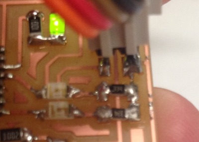
I needed to calculate the bias resistor for the phototransistor based on expected light level and desired sensitivity. In order to calibrate in an intuitive way (by eye, rather than lumens), I put a multimeter across the pins of the phototransistor and measured the changing resistance as I pulled a desk lamp across it.
For the change in light level I would imagine reasonable for these, I measured the change in resistance across the pins of the phototransistor, and calculated the resistance required for a good potential divider.
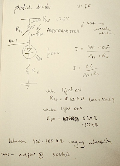
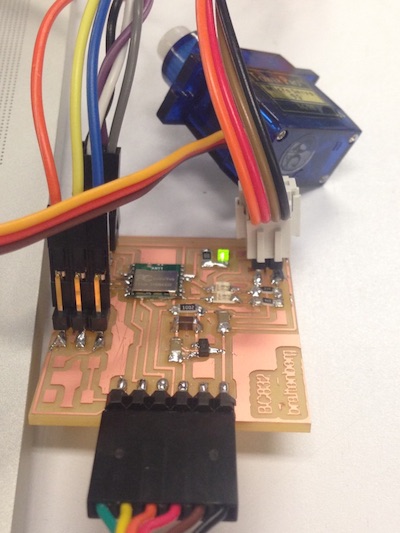
I borrowed some 330k resistors from Yun in Tangible -- slightly smaller than 1206, but with a bit of coaxing (just) fit each leg on pads either side of the trace. I should've done the calculations before milling the board; it would've been easy to substitute 3 1M resistors in parallel to produce the same effect.
I had also been meaning to test compiling C directly from the command line, so I tried out the SAADC example given by Nordic on their website. I flashed the hex file to the chip, and realised that, despite the code specifying outputs (e.g 'x voltage on port y'), I was at something of a loss as to how to listen to them. At this point, it was getting late, and I decided to have a better go tomorrow afternoon.
I followed the instructions for GCC development, looking at a github repo dedicated to this. Ideally, I wanted to be able to develop using GCC and C++, instead of the arduino environment. I had a little more trouble building the bluetoe repo -- it turned out my path variables had been altered (by me, obviously, roughly 10 commands back), and I reset them using:
Unfortunately, during the compilation stage, I managed to accidentally fry chip by flashing a wrong hex file to it, and couldn't erase using nrfjprog! really annoying. stick with arduino interface for now. I wasn't able to get the input working on the nRF52 this week (~~voice from the future: or indeed ever~~), but I *did* make it work quite happily on the ATMEGA 328p for my final project.
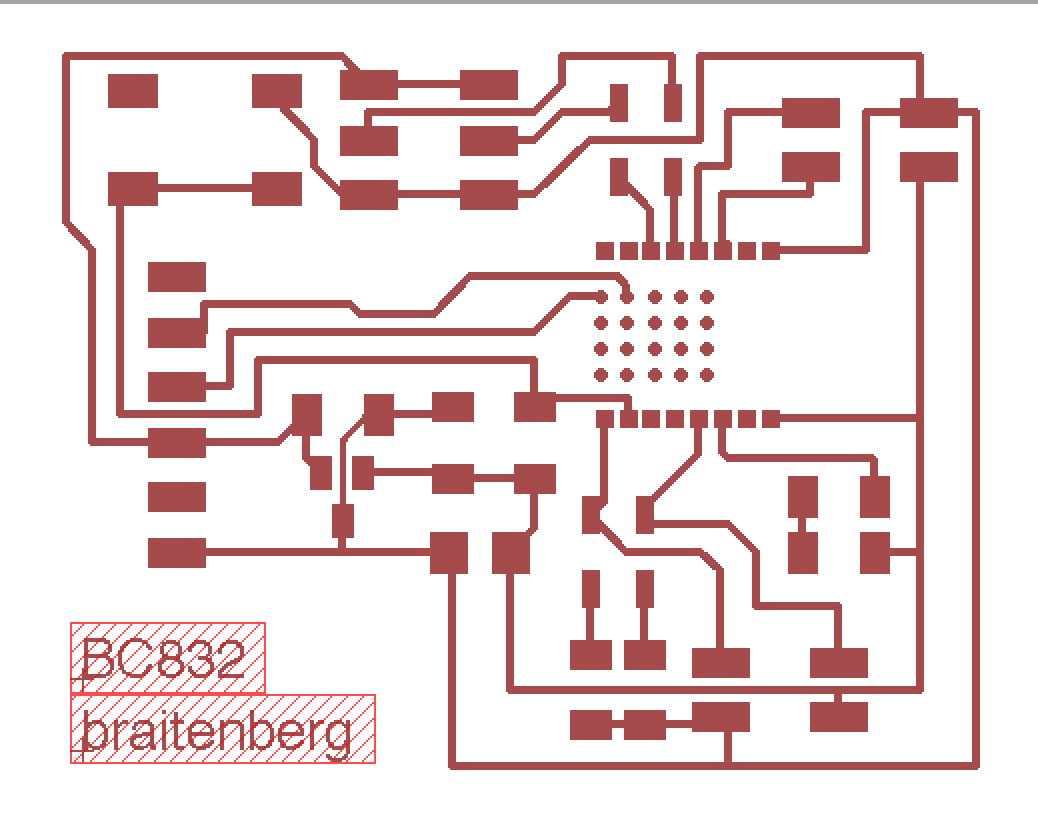
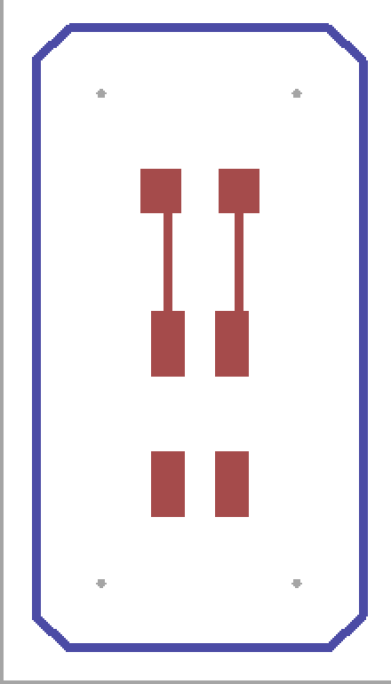
board design and fab
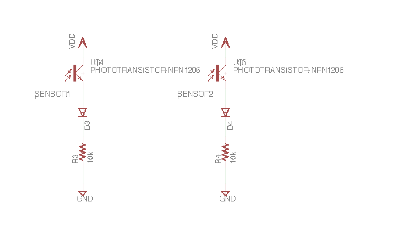
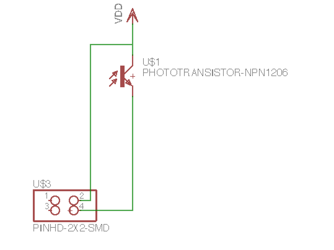
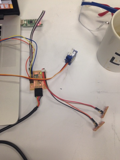
I began with a weird problem in Eagle where I couldn't select parts and move them on board layout -- turned out to be because the 'torigin' and 'borigin' layers were unselected. Once I'd resolved that, I added 2 sensor inputs to the existing board I'd made for outputs two weeks ago. Added in 2 light sensors -- one to AIN0, another to AIN1
Want to power
I needed to calculate the bias resistor for the phototransistor based on expected light level and desired sensitivity. In order to calibrate in an intuitive way (by eye, rather than lumens), I put a multimeter across the pins of the phototransistor and measured the changing resistance as I pulled a desk lamp across it.
For the change in light level I would imagine reasonable for these, I measured the change in resistance across the pins of the phototransistor, and calculated the resistance required for a good potential divider.
I borrowed some 330k resistors from Yun in Tangible -- slightly smaller than 1206, but with a bit of coaxing (just) fit each leg on pads either side of the trace. I should've done the calculations before milling the board; it would've been easy to substitute 3 1M resistors in parallel to produce the same effect.
programming
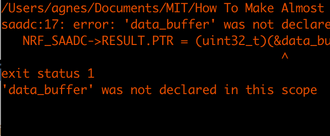
I didn't get very far with this part, and need to spend a while longer on it this week. I'm still not entirely sure of what I'm saying to the chip, and, likewise, how to get it to talk to me back. As such, the SAADC programs were quite difficult to debug. At first, I tried Sam's arduino SAADC sketch, though this threw a bug that I wasn't too sure how to fix, not knowing where the referenced buffer was missing from, or whether it could be found.
I had also been meaning to test compiling C directly from the command line, so I tried out the SAADC example given by Nordic on their website. I flashed the hex file to the chip, and realised that, despite the code specifying outputs (e.g 'x voltage on port y'), I was at something of a loss as to how to listen to them. At this point, it was getting late, and I decided to have a better go tomorrow afternoon.
progress
Installing GCC ARM embedded tools, following instructions from here. Nordic's instructions are a bit confusing: they seem pretty hot on you buying the dev kit version of the board (instead of configuring it yourself), and recommend different things in different places (including Eclipse!).I followed the instructions for GCC development, looking at a github repo dedicated to this. Ideally, I wanted to be able to develop using GCC and C++, instead of the arduino environment. I had a little more trouble building the bluetoe repo -- it turned out my path variables had been altered (by me, obviously, roughly 10 commands back), and I reset them using:
  PATH="/usr/bin:/bin:/usr/sbin:/sbin:/usr/local/bin:$PATH" # double, not single quotes

export PATH
Unfortunately, during the compilation stage, I managed to accidentally fry chip by flashing a wrong hex file to it, and couldn't erase using nrfjprog! really annoying. stick with arduino interface for now. I wasn't able to get the input working on the nRF52 this week (~~voice from the future: or indeed ever~~), but I *did* make it work quite happily on the ATMEGA 328p for my final project.