thoughts about swarms
ad hoc networks
robot shape
wheels
signals+spacing
finalising designs
to do + plan
robot structure
steering
spiral development: braitenberg vehicles
electronics design
input
output
power supply
testing
thoughts on the project / evaluation
Over the past couple of years I've become increasingly interested in self-organising systems and swarming behaviours. In particular, I'm interested in the application of ideas we get from swarms to problems of organisation on a human scale, for example, in the formation of mesh networks, or in the design of cities. Having done some of agent based modelling to explore these ideas computationally, I'd like to use this class to get a chance to realise some of these ideas 'in the flesh'
One idea I'd like to explore is that of urban patterns: patterns of city formation that are governed by sets of rules both top-down and bottom-up. Architects such as Ekim Tan use these urban rules as the basis for 'city games' -- where residents of a particular area are given the power to modulate and change their built environment, within the bounds of these 'rules' that establish particular criteria for the area. After a (fun, silly) project I did last year involving termites failing to make street plans I'd be interested to try and practice a city game with a real swarm, while adhering more closely to urban rules.
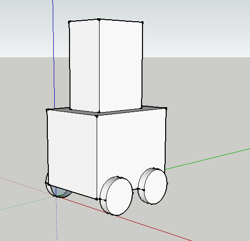
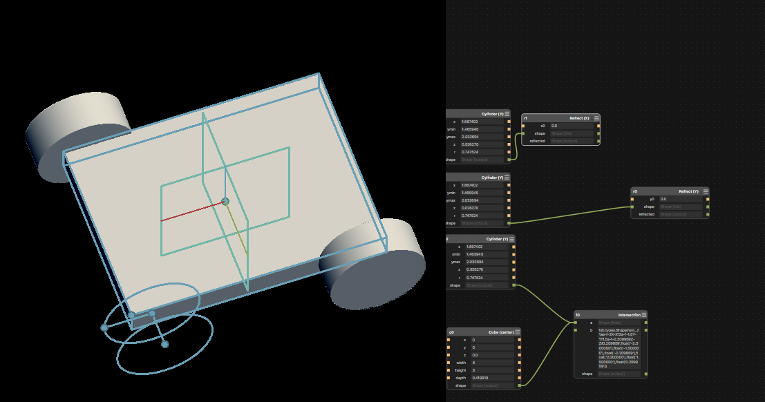
I found Antimony actually more intuitive than a few of the other CAD packages, though that could have been down to its relative simplicity. I managed to design a (very) basic chassis, which I'd like to return to. I also experimented with FreeCad (I found this very hard to do anything in), and with Fusion 360 (tough at first, got better as it went along).
As such, a simpler morphology might actually lead to more interesting things, and possibly give opportunities for a more exciting body than a simple grid with different buildings on it.
the zooids (stanford shape lab) are a nice example of a swarm -- these little guys don't truly self-organise (they're all centrally controlled), but have a neat form and move well. They communicate via a local network, where each bot talks to a central server. They rely on a projector-based tracking system to feed back position information
I did my final year dissertation on self-organising swarm networks, specifically looking at an organism called Physarum Polycephalum, which is a unicellular, multi-nuclear slime mould. Physarum navigates its environment using a simple set of protocols enacted locally by each nucleus in the slime, and is able to construct complex minimum-distance networks using no centralised control. Whilst the models I was using might not be optimal for a system of < 100 agents, I am still interested in Physarum-inspired networking and organisation, such as the protocols discussed here
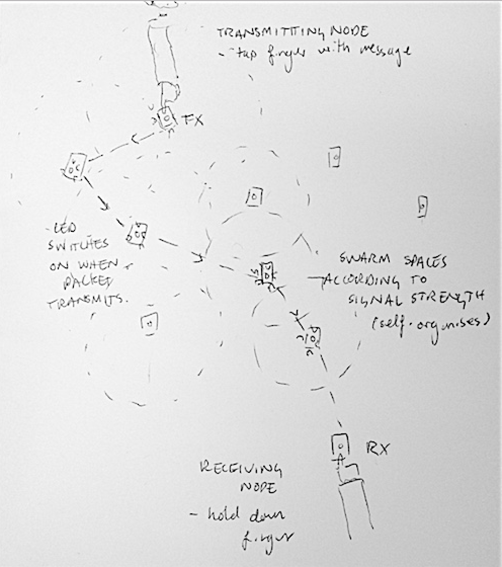
One idea I had to make this network demonstrate its function would be to make it interactive: touch sensors on each robot could take inputs that could declare the bot a tx or rx node, and LEDs on each node to indicate packet transmission.
One idea I'd like to explore is that of urban patterns: patterns of city formation that are governed by sets of rules both top-down and bottom-up. Architects such as Ekim Tan use these urban rules as the basis for 'city games' -- where residents of a particular area are given the power to modulate and change their built environment, within the bounds of these 'rules' that establish particular criteria for the area. After a (fun, silly) project I did last year involving termites failing to make street plans I'd be interested to try and practice a city game with a real swarm, while adhering more closely to urban rules.
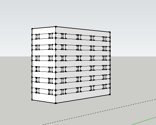
3D modelling
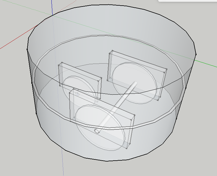
My 3D CAD experience is fairly basic (Sketchup and not much else), so this week was a real challenge for me. It took a long time to be able to move things about, and I'd like to return to this task after I've got a bit happier with a particular package. I started to think about how my buildings might look in Sketchup: as ever, boxes are easy to build, with more complex shapes introducing some strange artifacts when extruded.
I found Antimony actually more intuitive than a few of the other CAD packages, though that could have been down to its relative simplicity. I managed to design a (very) basic chassis, which I'd like to return to. I also experimented with FreeCad (I found this very hard to do anything in), and with Fusion 360 (tough at first, got better as it went along).
thoughts about swarms
Since week 2, I'd been thinking about the complexity of the project I want to undertake, and the idea of doing one smaller thing well (a la week 3) rather than a less focussed, overly-ambitious task. I've also been going to the Computer Networks class as a listener, and have become interested in developing some kind of networking element to the swarm.As such, a simpler morphology might actually lead to more interesting things, and possibly give opportunities for a more exciting body than a simple grid with different buildings on it.
the zooids (stanford shape lab) are a nice example of a swarm -- these little guys don't truly self-organise (they're all centrally controlled), but have a neat form and move well. They communicate via a local network, where each bot talks to a central server. They rely on a projector-based tracking system to feed back position information
I did my final year dissertation on self-organising swarm networks, specifically looking at an organism called Physarum Polycephalum, which is a unicellular, multi-nuclear slime mould. Physarum navigates its environment using a simple set of protocols enacted locally by each nucleus in the slime, and is able to construct complex minimum-distance networks using no centralised control. Whilst the models I was using might not be optimal for a system of < 100 agents, I am still interested in Physarum-inspired networking and organisation, such as the protocols discussed here
ad hoc networks
I've been attending the Computer Networks class this term as a listener -- yesterday's class was on ad-hoc multi-hop networks. This is a field I've been interested in for a while, and it was great to have a formal lecture on it, which introduced a number of routing protocols and planning tactics. What I'd really like to do is build a self-forming multi-hop network.One idea I had to make this network demonstrate its function would be to make it interactive: touch sensors on each robot could take inputs that could declare the bot a tx or rx node, and LEDs on each node to indicate packet transmission.
thinking about robot shape
E-pucks are pleasingly round, and might be nice for the robot construction. The round surface could be 3D printed (however, that's a slow means of constructing many robots, I'd have to settle on a design early and print in batches), or laser cut flexure. Alternately, for simplicity, a rectangular chassis might be a bit simpler. When I've built robots in the past, the best turning motion I'd had was to use two servos, driving one back and one forward to turn.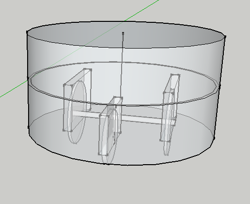
the nRF52
This is the chip I want to use for the final project. It's a good, lightweight RF chip for networking and embedded programming. Talking (or, for now, trying to talk to) the chip is discussed in detail here, and I plan to use next week (output devices) to link this chip to a couple of servos, and get a robot driving around.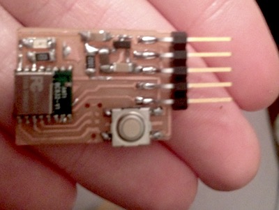
revised chassis design
In order to produce a simpler design that will be easier to replicate en-masse, I might scrap the idea of a circular board for something simpler to replicate (though, time allowing, making this part of the design visually appealing would be good). For now, I will test using a simple cardboard chassis, and once this works think about adding to it and changing up materials (acrylic might be best for this).
wheels mk 1 and 2
In moulding and casting week I used a 2-part mould to produce some fairly ropey wheels. However, at the same time, someone else in the class did a much better job using insert moulding to set a wheel rim in Oomoo for a laser cut wheel hub.This is simple, but really effective -- would be a good way to produce the wheels for this project.
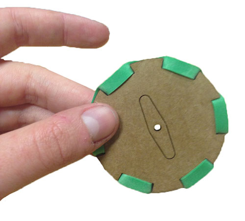
Yet another good wheel idea is discussed here, which uses elastic bands to form 'treads' around the rim of a small wheel. This design is really ingenious and would
powering BLE
The nRF52 uses BLE, not WiFi at the data link layer. BLE -- Bluetooth Low Energy -- is a low-power protocol often used in IoT devices. It's bad for transferring large amounts of data quickly (something WiFi/802.11 is very good at), but for these purposes it will be enough.Aside from the chip, however, a main source of power consumption will be the servo motors. In order for the robots to move independently, they will need to carry power on board; however, servos can quickly drain batteries. A number of coin cells in parallel might be a good way to manage this.
signals+spacing
Nordic have support for a protocol called nrfOpenMesh -- an open source implementation of BLE mesh networking using the NRF family of chips here. The protocol floods each node in the vicinity with the same signal.BLE mesh networking is not as established a field as the wireless mesh network, however it will be interesting to experiment with this using the nRF52s. If this doesn't work well, I could also use a WiFi chip with a B.A.T.M.A.N implementation of PirateBox (free, open-source networking system).
I've also experimented in the past with using BLE to determine the rough spacing of different objects, and this could be useful in localising each node. One of the issues to overcome is that BLE constantly 'channel hops' (adaptive frequency hopping) that can give a large error in distance measurements. A methodology for doing bluetooth localisation with reasonable accuracy is given in this paper.
finalising design
to do for final project: Final Design: swarm of robots Aim to construct 10 robots. Aware this is a large number, need to construct in batches rather than 1-by-1. Using time effectively (e.g. finding a software task to do while milling 10 boards, laser cutting 10 chassis), will be really important. Extension: BLE/radio mesh network -- LEDs on robots show packet switching swarm organisingto do list
modelling
- finalize chassis and wheel design
- model inset mould for wheels
milling/moulding:
- mill inset mould for wheels
- cast laser cut wheels in Oomoo rim
- there's also this <-- doesn't involve moulding but really cool and would save some time, should test both
laser cutter:
- test chassis (in cardboard)
- laser cut wheels + robots in acrylic
electronics:
- finalize board and chip used (nrf52 or other?)
- mill 10 boards
- add a 'packet send' sensor or button (input)
software:
- finalize sdk used for chip (adafruit?)
- finalize protocol used (first for self organizing, then, if used for networking)
- figure out steering (1 servo off, other on OR 1 fwd 1 backward), driving servos
- terminal interface to see relative placement of robots? at the very least start/stop
order of tasks:
- get basic nrf52 working, work out framework of program (servos controlled by signal strength). If this can't work then new chip asap
- test chassis layout in cardboard
- start working on software now in order to have something to do whilst milling boards
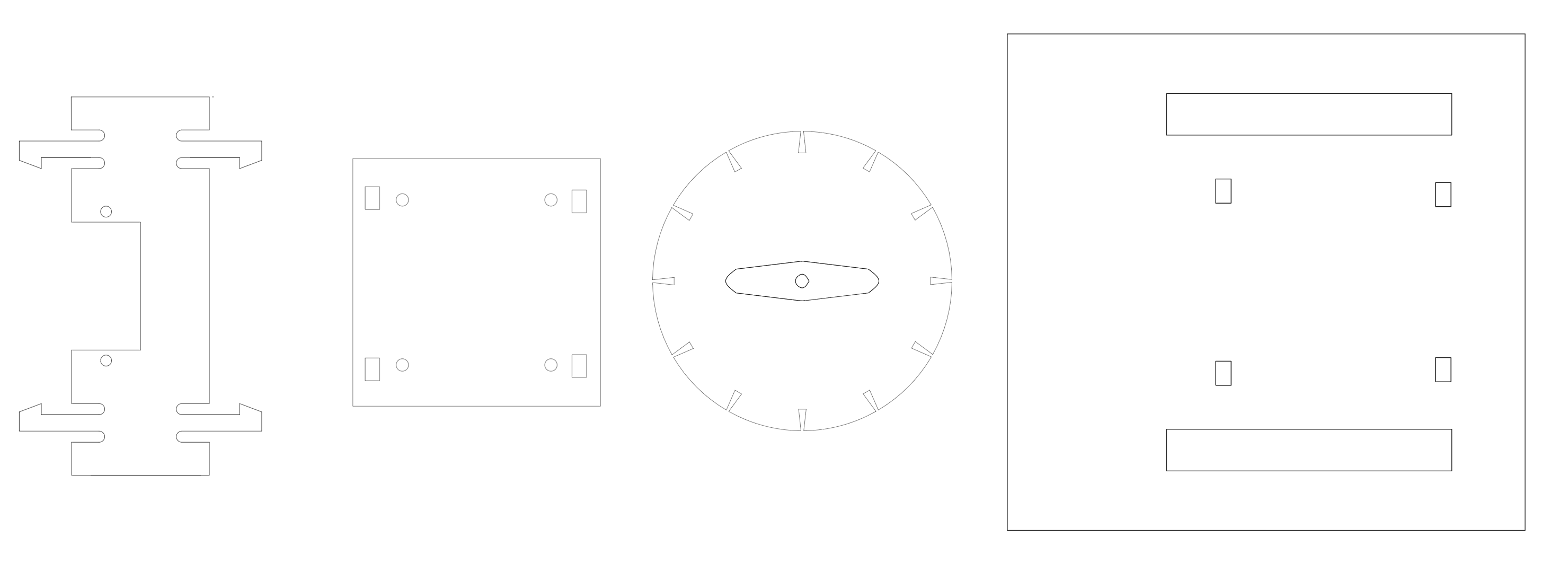
designing and building the structure
One of the things that has been really new to me for this course is CAD, and I'd still yet to really make a decent job of assembling components in 3 dimensions. I made the model by starting simple, then extending into more complex shapes. Some of the functions that made life a lot easier were using midplanes and mirroring -- requiring only about half of the forms to ever be designed.wheels
The first thing I wanted to test out were the wheels. I decided to make the laser-cut elastic band for now, and extend to moulded rims if time permits. First, I tried just laser-cutting the file, but the notches were the wrong size for the scale I wanted to use. I drew my own version in Fusion360: my first attempt was too large for a standard elastic band to get around, but my second attempt worked well. Cardboard prototypes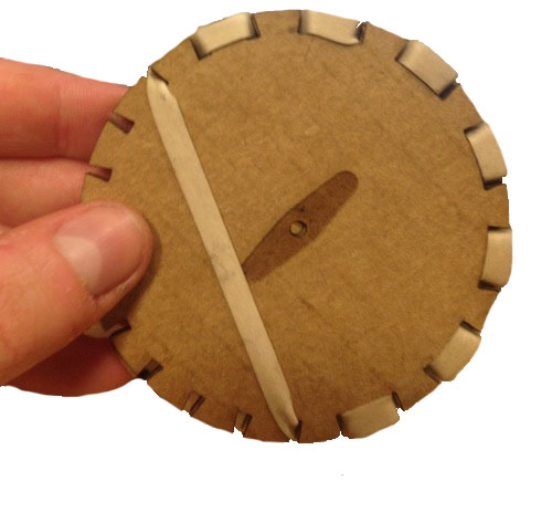
laser cutting acrylic
I cut all the parts using the GCC spirit GLS, which is a lower power rating than the Epilog, but considerably more reliable. -- after a couple of attempts where the dpi was set too low, I settled on speed 0.6, power 95, PPI 685, which gave a nice cut. That said, it also got quite hot, and caused overly-fine features to melt. This could be solved by few attempts -- even at normal 'good' cutting temp, small, laser-intensive features can melt.The problem I'd been having was where the 'mode setting' of the printer was set -- it was using only Using the designs 3D feature for the GLS was really good, made the mistake of changing the colour -- couldn't fit servo screws Aligning the etched part of the wheel horizontally rather than vertically saved a lot of time, as the cutter rasters in x, not y. Initially, I was having a bit of trouble getting rastering to work: I'd been using the pen settings to distinguish between colours, but it was only noticing black. Then, I found the manual. this guide is super helpful, and it was cool to find out about all the laser cutter's features, way more than I'd expected (stamp setting!). On the final cut of the wheels, John was watching and reckoned that the machine was going unreasonably slowly. It was a bit late to re-think the toolpath by then, but he reckoned that having a much faster cut and running it twice would achieve far better results.
On a particularly large job, my elbow knocked focus and it didn't cut all the way through. Instead of scrapping it (which would have wasted a lot of acrylic), I re-focussed the laser cutter, then re-aligned the machine along the initial cuts with lid open (so only the pointer was active), then closed lid to allow the machine to cut all the way through.
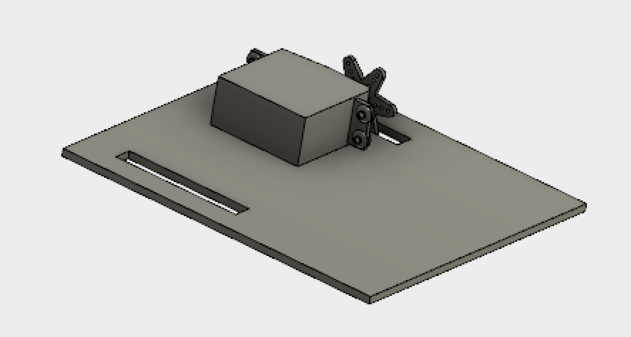
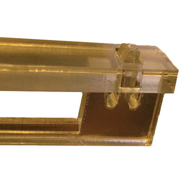
snap fit servo mount
In order to hold the servos in place, I needed some way to house them. Servos are an awkward size: in the past I'd just used a glue gun and cable ties but thought I would do a better job here. It's possible to download a lot of standard parts from GrabCad Used an acrylic snap fit joint based on the design outlined here, which is a great resource on different laser cutting techniques. The first, the snapping components were too fine and the plastic melted. they were very fragile, and easily deformed plastically, making them unsuitable for repeat uses. In addtion, I'd mis-measured the thickness of the acrylic with the calipers (having confused the mm and inches reading).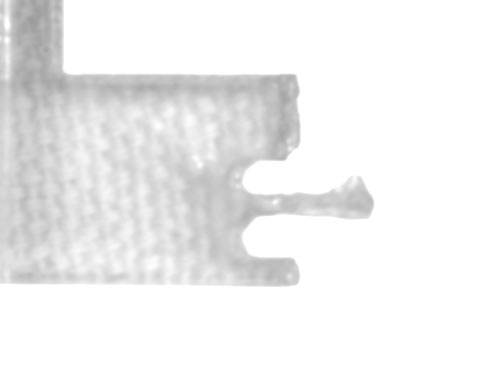
Once I got it right, though, the snap was really effective. This was also one of the first designs I'd done where the I got the parametric constraints fully working: modifying one parameter didn't turn the rest of the drawing into a tangled mess, and this was pretty satisfying. One of the things that really saved me time was the 'mirror' tool; I'd not been using it properly before and it was fantastic for highly-symmetric components.
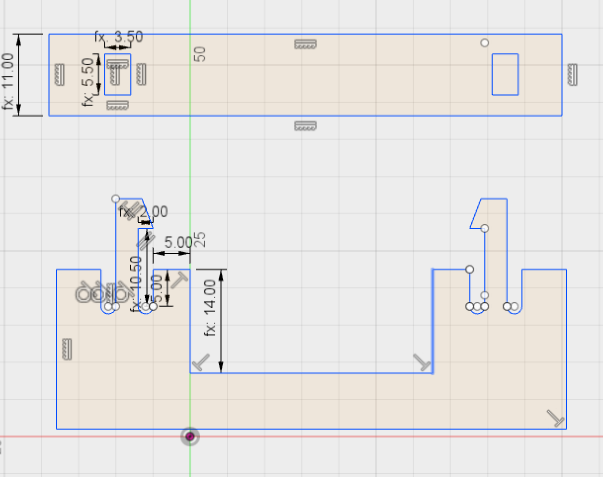
The snap-together joints formed the basis for the rest of the chassis, with
assembly
This was the part I really wanted to get right: I'd made mistakes in the past by putting all the sketches in the same file, or not separating bodies, that had made this step very hard. This time, each component sketch was separate, and the extruded components (all of which had the same materialthickness parameter), were assembled along with a .f3d servo component whose dimensions matched that of the servos I plan to use.
The initial tests of the chassis and frame worked well -- I need to wait for the casters to arrive (projected: Wednesday) to assemble the full frame and start making many of them. As the laser cutting job for each set of parts takes about 15 minutes, once a working frame has been tested it makes sense to cut a load at once. screws -- 2-56 x 1/2 adding in other solid parts like the servos changed the 'snap' properties of the acrylic parts, which mant that the failure rate by cracking increased from ~10% in tests to ~50% in the final assembly. This was really frustrating; the parts were small so not too much wastage but still something about damping properties and force distribution -- can't deflect inward.
adding in the front sensors and caster
In order to mount the sensors and caster on the robot, I needed to add to the CAD drawing: here's a gif of the evolution.
construction
In the end, it took a few iterations to get the design quite right. This was largely due to my failure to think about the 3 daughter boards (2 light sensors and power regulation) initially, requiring a second chassis design. There were a couple of other, more subtle iterations that would've been harder to forsee: the initial snap joint worked great, but adding in the servo changed the force distribution in the material (and the servo had to be added in first, or it wouldn't fit in...). This meant that I had to make the chassis slightly more forgiving to the lower snap joints, which meant moving the far edge out to allow room to deflect more (the parts snap to the inner edge, so this didn't make the robot wobbly).That said, once everything was well cut, these were really happy things to make -- the part that took the longest was normally finding the screwdriver to mount the servos.
aside: how to make (almost) a time-lapse
so I really like little timelapses, and thought I'd try making one. It turns out to be really easy on an iPhone with iOS 8 or greater, so I taped a length of scrap wood to a stool, put it on the table where I was working, then taped my phone to the end of it. I ended up making two -- neither particularly good -- in the first you can't see my hands properly, and in the second you can *only* see my hands. By the time of the second, that was my final robot under construction, and I was loath to take it apart again to get a better shot. However, the effect is still nice, and I would like to do more.braitenberg vehicles
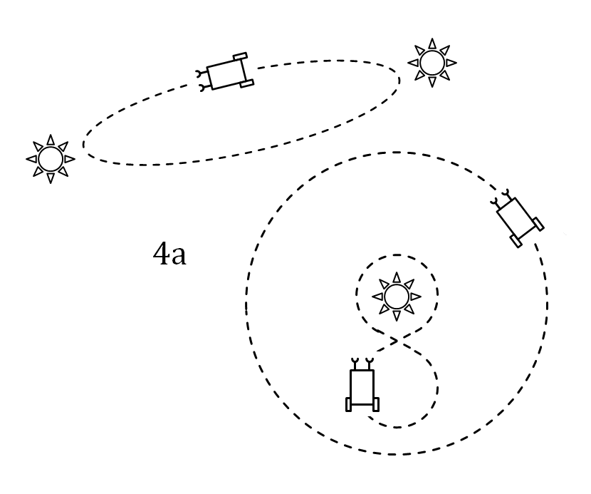
In the spirit of spiral development, and given some of the issue I've been having with networking, I thought that a good first project would be to build a couple of braitenberg vehicles, then see if I could get them to talk to me. Then, if they did, I'd get them to talk to one another. (as per the original design).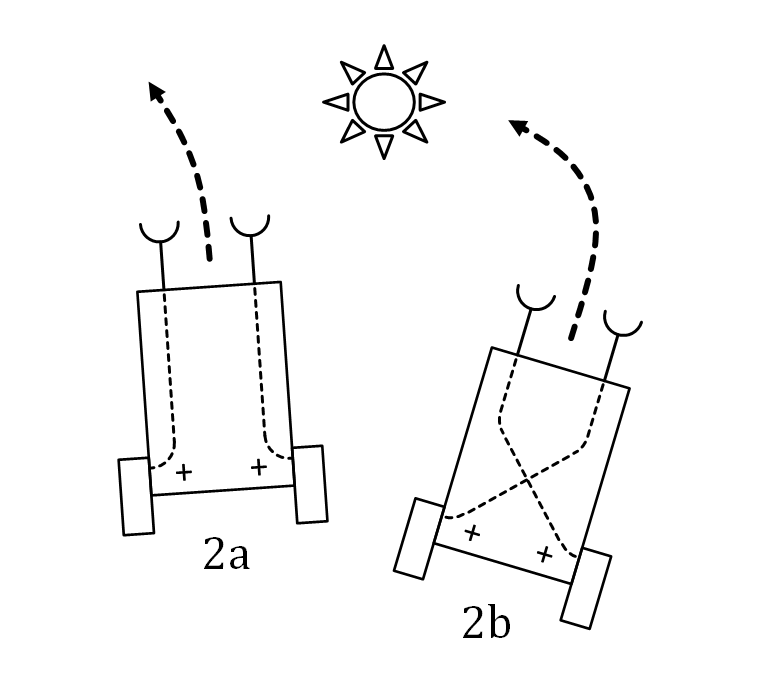
Need to make sure that the electronic and mechanical design can support the extension -- for example adding in the capacity for a networking chip.
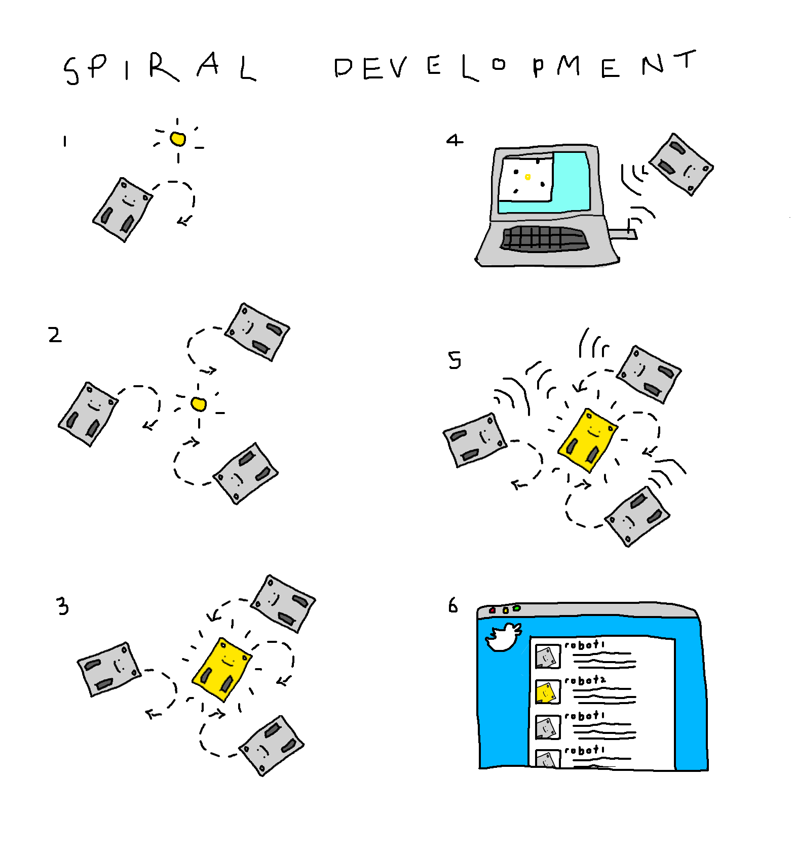
- 1. Single braitenberg vehicle -- reacts to light and drives around. Servos/sensors reconfigurable
- 2. Many braitenberg vehicles: explore the reactions of different morphologies
- 3. A 'light vehicle' moves through the swarm and disrupts the other vehicles
- 4. A many-to-one interface between nRF24LO1 chips on the robots (tx) and a serial port receiver allows an interface to be designed that shows updates from hte bots
- 5. The robots talk to each other (many-to-many) using the nRF24L01 mesh protocol
- 6. each robot gets a twitter account. possible tweets include: 'there's a light' etc.
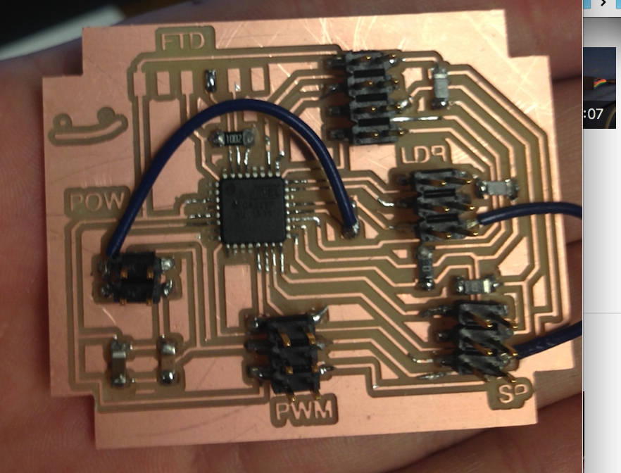
designing the electronics
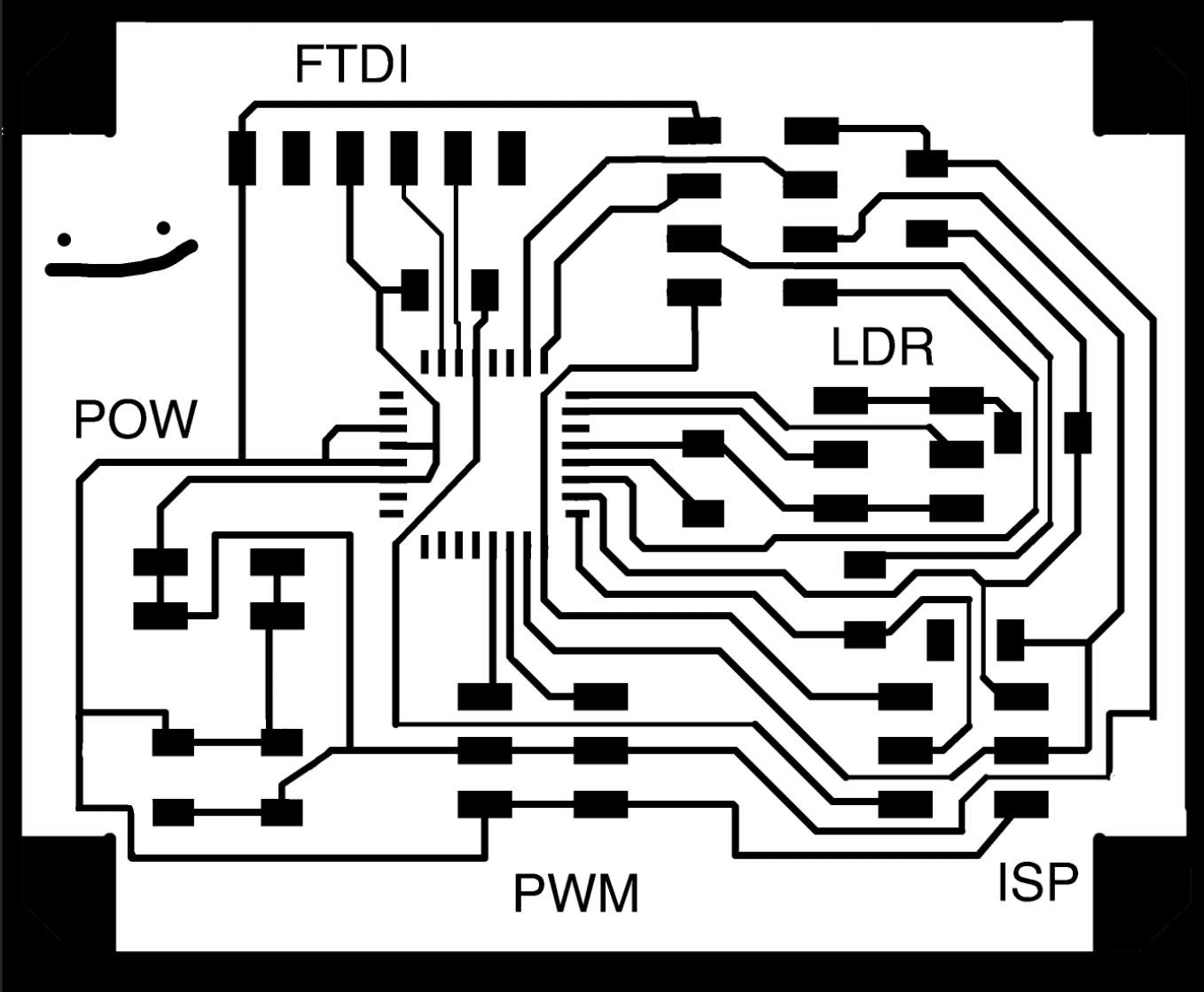
I originally wanted to use an ATTiny85 for this -- it would allow me recycle my nRF24L01 baord, and was sufficiently simple to make the development of the sensing/actuation mechanism more a function of the code I'd be writing than endless hours of trying to figure out what was wrong with the chip. However, on coming to design the schematic, I realised that I woudn't have sufficient pins available to communicate with the 2 sensors, 2 servos, the ISP, FTDI and NRF24L01 (plus, even if I were, I'd be a bit stuck if I wanted to add anything else). I chose instead the ATMEGA328P, which has a good number of pins (23-pin GPIO) and a lot more memory to extend the project.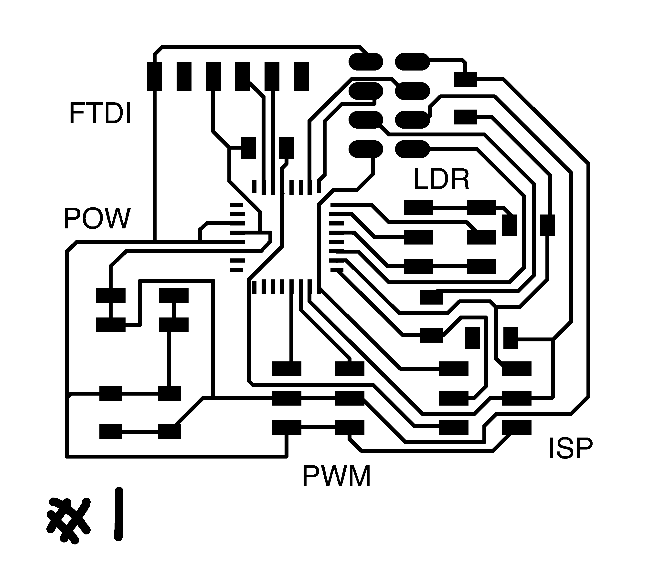
Snap on circuitboard
In order to make a robust (and hopefully nice-looking) robot, I wanted to extend the press-fit functionality to the electronic components. As such, the motherboard (above) snaps to the top supports, and the two front sensor boards push-fit around the routed leads, through holed in the front mounts.modularity
I wanted to make sure all of the daughter boards can be swapped out for other things. Originally, the input circuit only had light sensor and 2 terminals, with resistor and ground housed on the motherboard. However, I realised that if this were to be swapped around this would be inflexible, so made instead resistor, input and ground all on daughter board.input
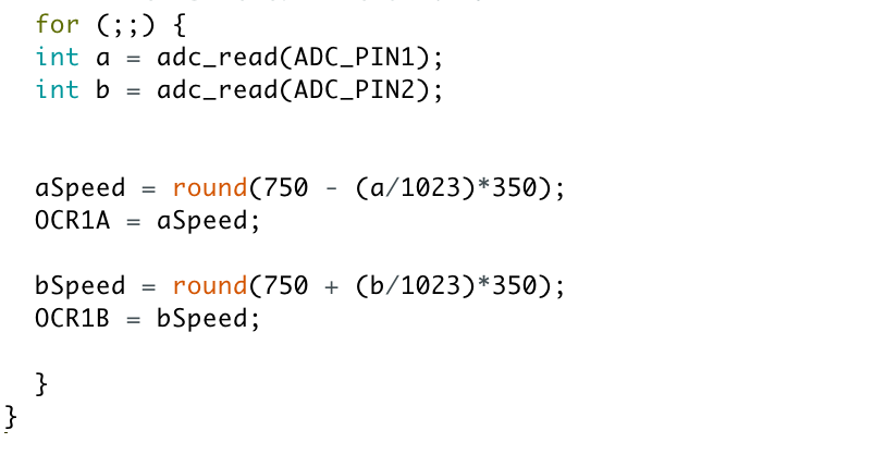
For the input to the robot, I chose to use the phototransistors I experimented with in week 11. Though I didn't get a working board then, I had tested the resistance of the light sensor. I realised (eventually...) that the values I'd calculated in week 11 were for the phototransistor in reverse bias, and significantly higher than the correct readings. Part of the confusion was that, unlike all the LEDs I'd been using, the green pin which I assumed should point to ground was actually the positive pin of the chip. This caused a great deal of confusion initially, but was eventually resolved when I put a header on the wrong way accidentally and got a much better reading out.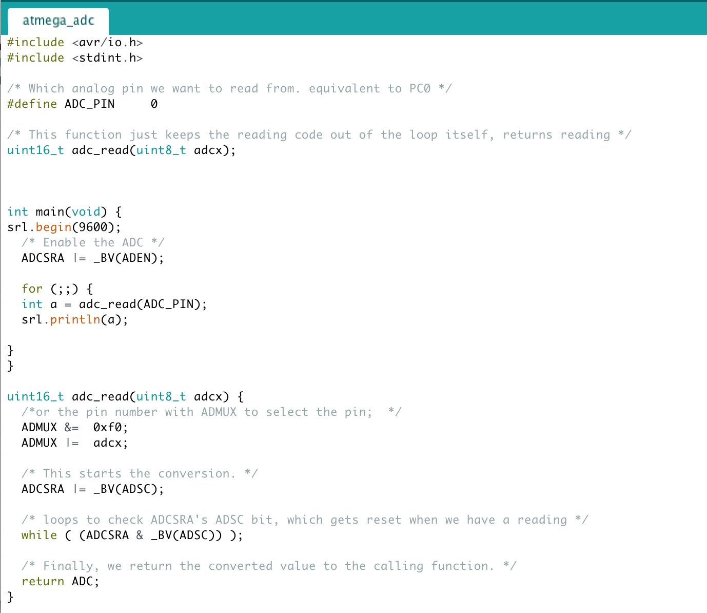
The code above shows the process for reading an ADC pin -- first the pin is declared (in this instance PC0) The 10k resistor value given on the site worked really well, and just using a multimeter I was able to get a good variation in readings. The next step was to connect it to the board, however, when I plugged it in I just got garbage. After a bit of googling it turned out that I needed to tie the AREF pin to VCC. I broke a chip trying to hack a connection onto the existing board (mistake), and so milled a second board, which worked great.
output
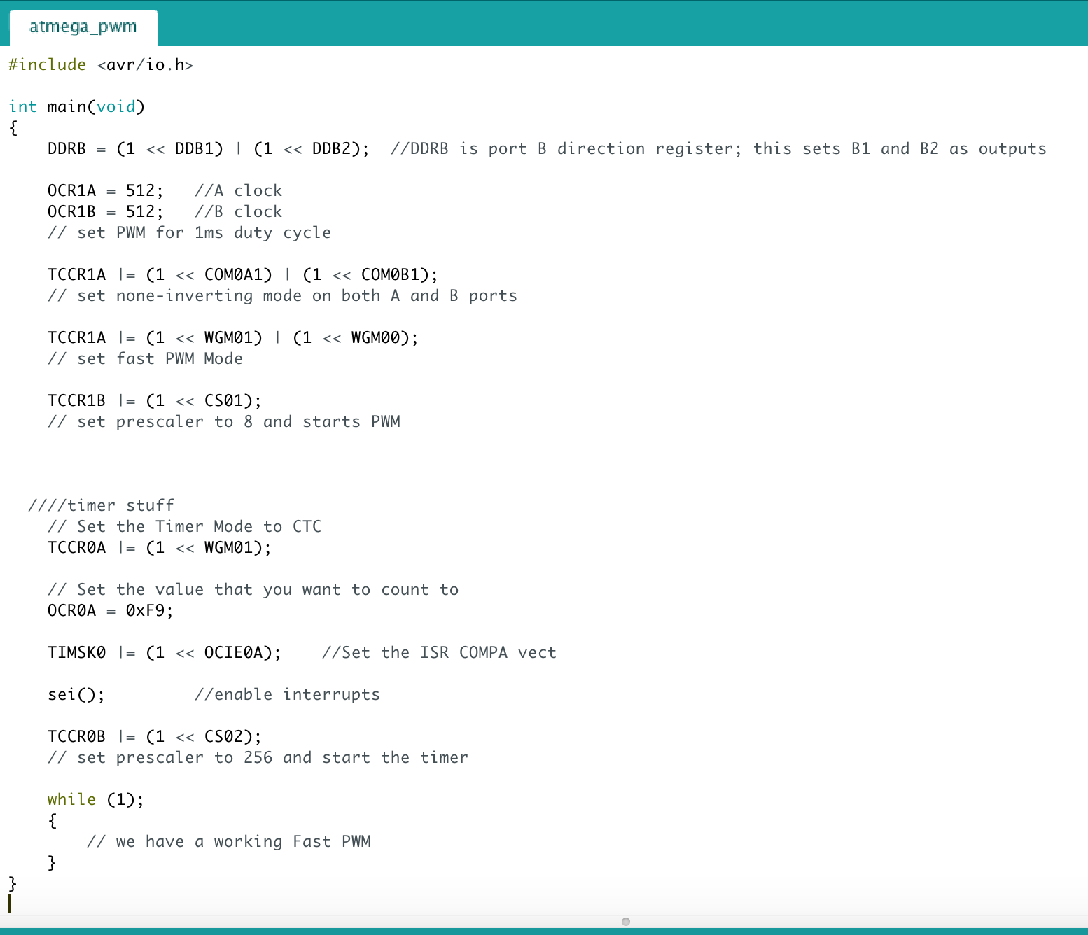
My first attempts at PWM with the NRF52 are given in my week 9 notes. This was one of the few successes I'd had with the nRF52, and I was reasonably confident about this. The ATMega328 has 6 pwm outputs configured by 3 different internal timers, indicated by OC0A/B, OC1A/B and OC2A/B respectively. I found this site a really helpful guide to pwm on the atmega328p, and this was great for timers generally.The PB1 pin has to be configured as an output (DDB1 set (one)) to serve this function. The OC1A pin is also the output pin for the PWM mode timer function. On my first board, I also ended up debugging a subtle short between the 2 PWM pins thatg was confusing the signal. timers on the atmega
configuring pwm
Jake came in at a crucial moment and suggested that, instead of me trying to drive the ATMEGA at 50Hz (as specified as a 'standard for PWM'), I should just use the already-working 500Hz clock speed to drive pulses at 1-2ms, without worrying too much about thw rest of the duty cycle. This worked great, and really sped things up. Timer output scales from 0-1023 -- as it's at 50Hz, 1023 is right on the 2ms needed to drive the servo forward at full power, while 512 is the max backward power. Thus, theoretically, at 750 (1.5ms), the servos should switch off -- this took a bit of tweaking but eventually worked. This video shows a light input toggling the pwm output between 750 and 1000.power supply
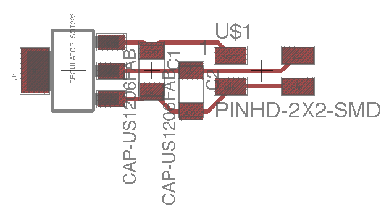
Accodring to the FS90 datasheet, each micro-servo draws 200mA in regular use, thus 400mA/robot. The chips will also draw some power, but in comparison this is relatively smallPowered on at 5V, this gives P = IV = 400*10^-3*5 = 2W. 2 watts is a lot of power. A standard energizer 9V battery has about 4 Wh of power -- theoretically enough to power the robots for 2 hours -- enough to demo, in theory, though it might be an idea to use two. Need to regulate down from 9V to 5V; there are a number of 1 and 1.5 amp regulators available, but no 2A regulators to hand. Tomás suggests using two in parallel, which sounds like a reasonable option. Haha, 2W /= 2A, the 1.5A regulators are FINE. (classic). So, all is well. I was getting a bit concerned about passing that many amps around. Still a lot of watts, but a bit more reasonable. Need to figure out where to put the battery.
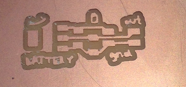
In addition to the regulator, this part of the circuit will need a heatsink, and some large decoupling capacitors, as shown here. I had initially made the regulator with no capacitors, and it did nothing! They're definitely necessary.
code development
For this stage, it was really useful to go in a spiral; the most obvious of the development phases.- first, burn bootloader
- test serial communication
- test single pwm
- then double pwm (after I got the code for pwm working, I only tested with this file)
- then single ADC
- then double adc (ditto)
- ADC printing on/off to serial port if above a threshould
- 1 adc writing to a servo on/off
- 2 ADCs writing to 2 servos on/off
- test digital on/off in the robot
- calibrate the direction and zeros
- analog signals in the robot
board-by-board debugging
The very first board I made with the ATMEGA328p, the ADC didn't work as AREF not set (see 'input'). In the second iteration of the board, everything ran pretty smoothly, which stood me in good stead for checking each manufacutrd board against a good standard. For each board, I ran a series of test scripts in the 'spiral' described above. This turned out to be a useful tactic, as it threw out a number of errors.- Burning board 3: wouldn't take bootloader, replaced chip and it worked great (from helping gary debug earlier knew that that wasn't very fixable if no obvious faults with the board). On reflection (esp after later debugging) it might have been that the board was powered, but one of the power pins wasn't well-joined (the SCK pin I checked for this problem.)
- Board 2: was a short on pwm that meant some of the code didn't work
- Board 3: again -- serial pin hanging, wasn't able to talk
what does it do?
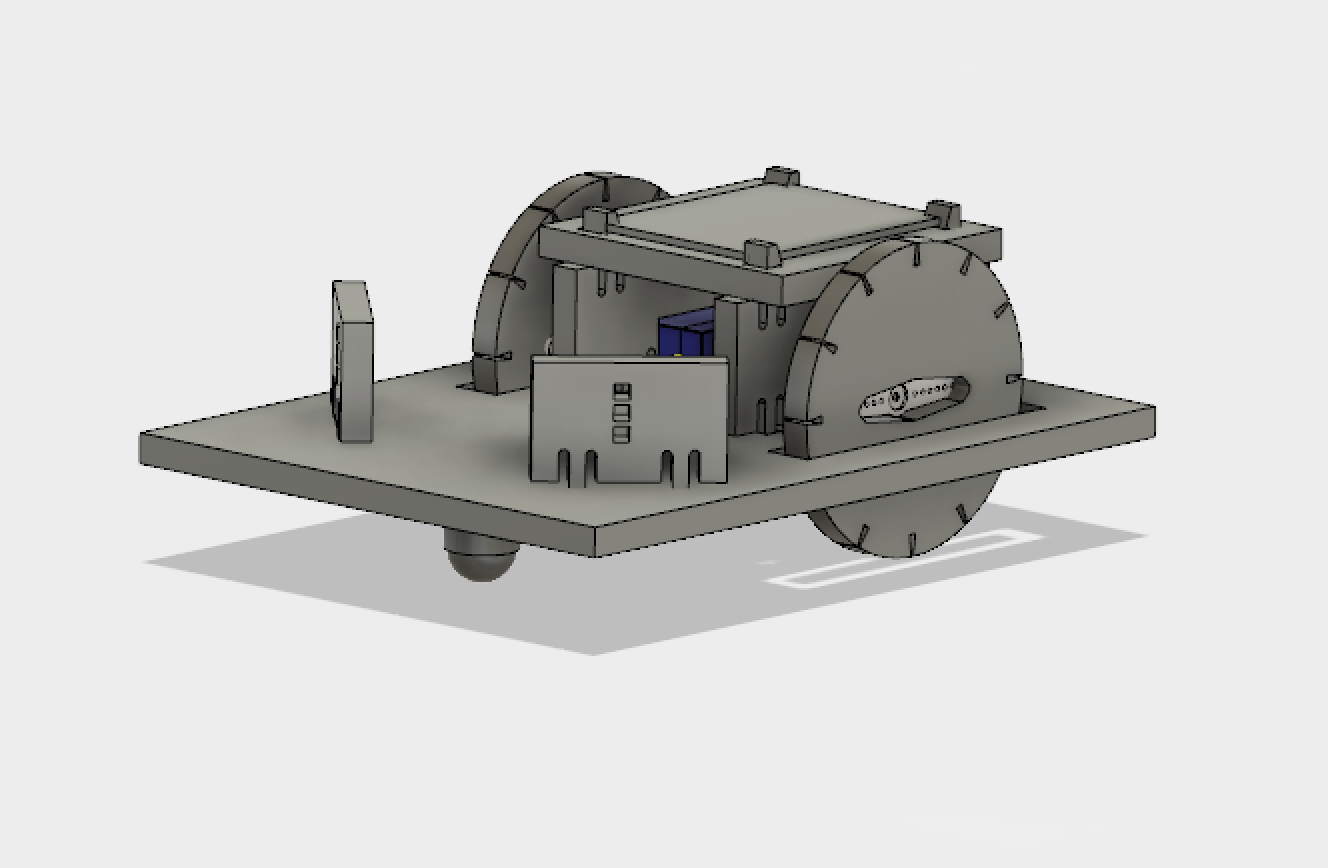
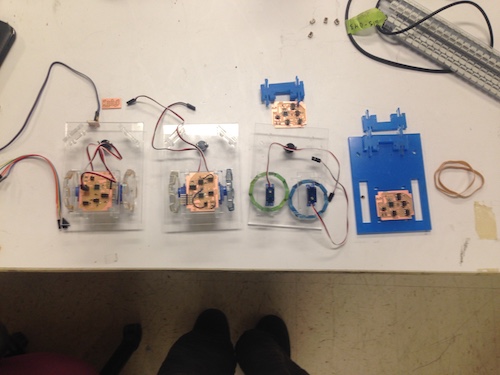
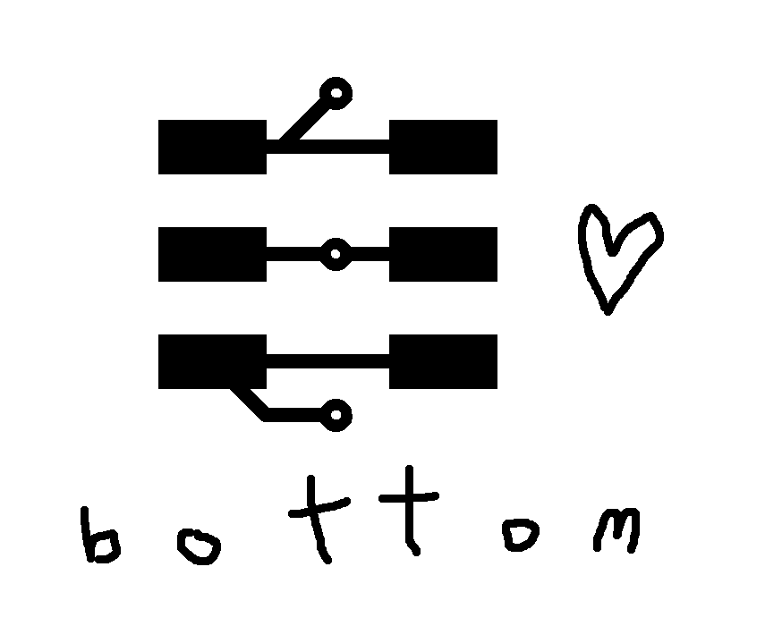
I made a small flock of Braitenberg vehicles: little robots that respond to light signals. They're a cool example of 'embodied intelligence' -- a way of thinking about autonomous systems not in terms of 'processing symbols' (such as an image-recognition system might do), but in terms of their own sensory perception. Each robot has 2 light sensors munted on the front, and two motors on the back, where the input from each sensor controls each motor. Depending on the configuration of the light sensors and motors respectively, different, seemingly complex behaviours emerge when the robot envounters light.
who's done what before?
Funnily enough, there have been 2 other Braitenberg projects, both in 2012: Jin Joo Lee made an underwater swimming robotic fish-vehicle that moved toward light, and Emily Mackevickus, who built a programmable vehicle that could be configured to move towards light (and to respond to other sensory inputs). On the swarm side, Abdullah Ibrahim's polybotics project has some nice vibrational robots, and there's obviously of course Julia Ebert's project from this year, which involved re-creating the behaviour of sawfly larvae clustering. There are also a number of somewhat incomplete-looking swarm projects -- perhaps testament to the warning that making more than one thing is tough (I can concur).
what materials and components were used?
I created the body of the robot (including the wheels) from laser-cut transparent acrylic (5.8mm thickness), using elastic bands to create the wheel 'grips'. The actuation of the robot was done with continuous rotation servos: motors would also have been an option, though are more awkward to integrate into a press-fit design, and would have required an additional daughter board to include the motor driver. (that said, I mainly just like servos). I used a front caster from Pololu; in hindsight, I could definitely have 3D printed these, and I'm annoyed I didn't -- I thought they would be a bit more complex than just a ball snapped into a cylinder, but they really weren't.
where did they come from?
The casters and servos came from Pololu -- they were a great supplier, I've definitely had dud servos in the past but all of these worked consistently well (and were pretty cheap, barely more than a DC motor). The acrylic came from the wonderful John+Tom (I imagine McMaster Carr...), the elastic bands were crowdsourced from Tom, the postroom and my office, and the electronic components I imagine hail from Shenzhen via Digikey.
how much did they cost?
The bill of materials for this project is roughly:
- 2 sheets of acrylic (12"x24") at $16.33/ sheet = $32.66 (add another sheet if you count failures/tests)
- 8 continuous rotation micro servos at $4.46 each from Pololu = $35.68
- 4 ball casters from Pololu at $1.89 each = $7.56
- 4 ATMEGA328ps at $2.18 = $8.72
- 2x phototransistors, regulator, resistors/capacitors ~=$1
- I used about 10 bolts/nuts that didn't come with the other parts so I guess we say $.50 for sundries
what parts and systems were made?
The mechanical parts of the system consisted of 2 wheels, and 2 servos, supported by a chassis and 2 clip-in servo mounts. To the chassis clipped 2 front mounts for the push-fit light sensing board, and on top of the servo mounts clipped a top mount, for a snap-fit top board.
The original design integrated a port for an nRF24L01, which would allow the robots to support networking
what processes did you use?
The main processes used in this project were CAD, laser cutting, milling, soldering and embedded programming.
what questions were answered?
- is it really entertaining to watch a little thing on wheels throw itself around looking for a light? yes.
- is it as funny if it tries to run away? yes, also.
how was it evaluated?
I'm pretty happy with my little robots -- a bit sad that I couldn't get networking to work (seemingly in any way, shape or form), but the part I knew least about coming into this class was CAD and mechanical design, and I definitely managed to do that part. Having things that snapped together (and only occasionally broke) was really exciting, as was getting parts like the servo arrive and fit exactly. It was a shame that we couldn't have hung around at the open house as the robots are a lot more effective in the dark. what are the implications?
morphological computing is pretty cool! it's exciting to be able to get an extremely simple system doing seemingly complex and interesting things, and it would be nice to push the concept further. One of the things I'm really interested in is to look at possible flocking behaviour by attaching lights to some or all of the flock (though to get interesting results I might need more than 4...)
milling double sided boards
I wanted to mill double sided boards to run the power cables out of the back of the light sensor, but realised that in the end I'd milled the 8 (8!) boards on single-sided copper. However, as the only thing coming out of the back of the board were 3 wires, I used male-ended jumpers and poked them through the via holes (actually a lot more efficient, if a bit of a hack). Drawings on boards come out quite nice (though they suffer if the mill cuts too deep).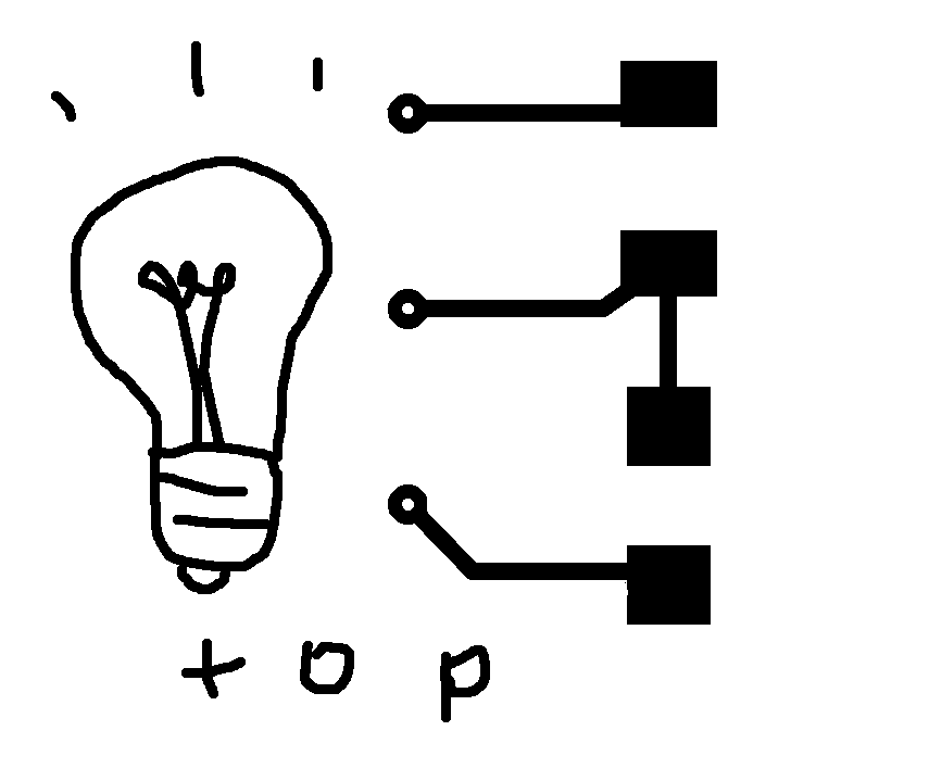
testing the robots
After I'd got the adc writing to the servos, I tested the robots -- they worked!thoughts + evaluation
As this page shows the whole process of thinking about the project (and its evolution over time), I thought it would be worth explicitly answering the questions from the 'final project evaluation' page, as the answers are addressed above, but somewhat nebulous and might be unclear.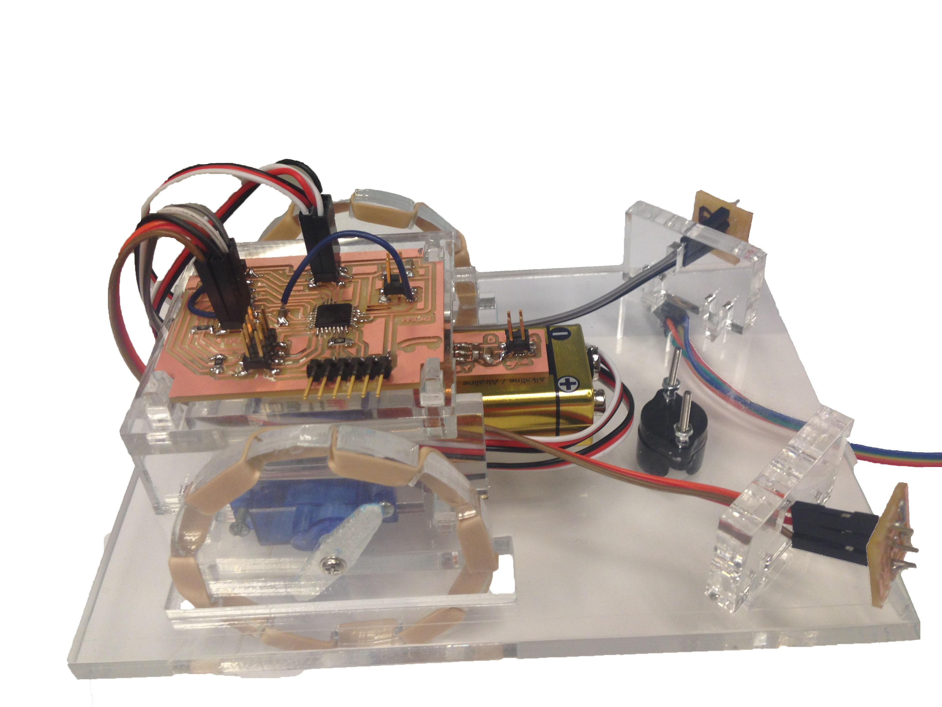
Were I to identify the difference between my project, and the ones before, I think the main difference with the others is speed of fabrication as a 'prefab kit', as the other projects are all molded or 3D printed, as opposed to laser cut.
On the electronic components end, the motherboard of the robot used an ATMEGA328p, a number of resistors (10k, 0), and 3 capacitors (10u, 1u, 0.1u). The sensor daughter board took a clear NPN phototransistor (couldn't find a part no. but really responsive! a lovely component, though confusingly the green end is *not* the cathode), and the regulator daughter board took a SOT223 5V LDO voltage regulator. There was an unfortunate mixup where a number of 3.3V regulators (identical in appearence) had been left in the 5V regulator drawer on the exam day -- I'd been using just one regulator board to test each robot till that point, so was really surprised when I plugged them all in and they didn't work. Luckily, there was just time to correct it (though only 2 5V regulators left, leaving one robot out of action).
For future development, ideally I'd like to get the networked component working, as that was factored in to the initial design (with the port for an nRF24L01), and also to develop a more responsive ADC-scaling system to make them robust to light changes (e.g in high-intensity ambient light, change the scaling to a narrower range). This would perhaps take the form of an initial 'ambient' input that would form the 'zero' of the pwm signal and then scale accordingly with the remaining variation between 1 and 2 ms.
In hindsight, 4 was a lot of robots; 3 would have allowed more time for testing, and resulted in less panic at the end. That said, I wanted a swarm, and a swarm of 3 wasn't quite enough. I learned a lot during the manufacturing process, and feel like I've had a lot more useful practice than if I'd only made one.
It's been really fun! Thanks to everyone that helped me out (both in the class and out). Lots of love from me and the robots...