Week 11: Input Devices
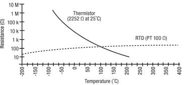
This week I got to play with a temperature sensor! This will be useful for my final project, especially as I'd never thought about much work needs to go into reading, understanding, and calibrating a digital sensor. I started out by following Neil's board and code on the class page for how to make a temperature sensor, and then did a bit of research into the joint humidity/temperature sensor that I'll be using for my final project. I chose the RTD sensor over the NTC thermistor because, as Neil told us and Digikey explains here, this temperature-sensitive resistor should be more sensitive at room temperatures. (Graph via Digikey, via National Instruments.)
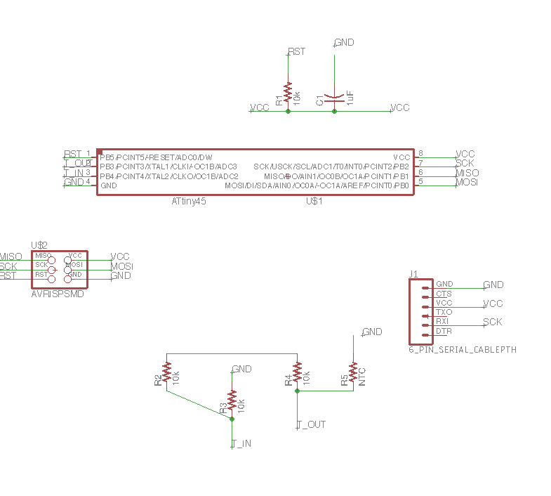
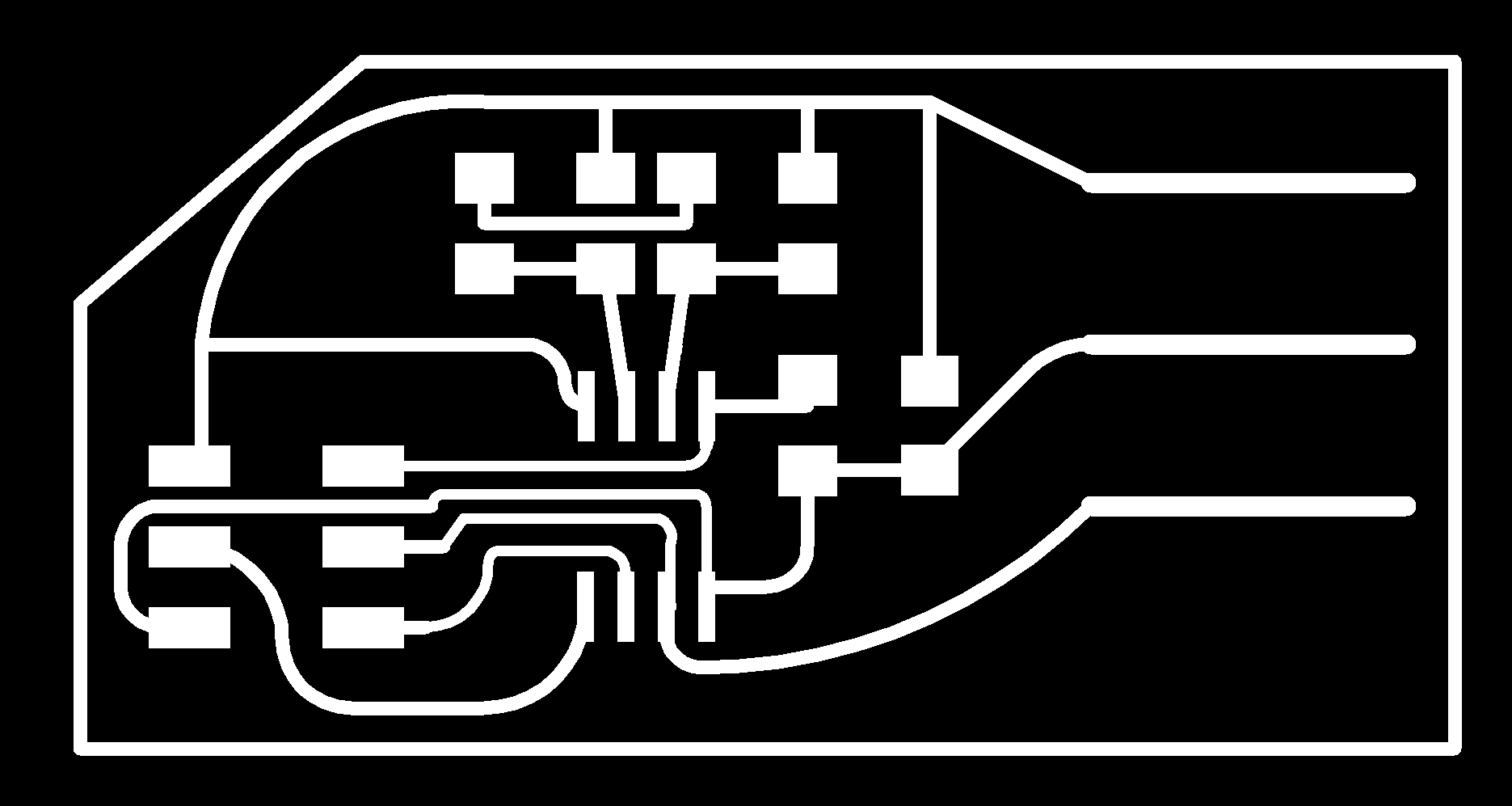
First I decided to redesign Neil's board, since I wanted to put a female FTDI cable and use this as a daughter board to my button board. Otherwise, I followed the same components and general design. I can also re-purpose this same board design to make several boards for humidity sensors, which I can then put around the trailer to measure the temperature and humidity in different parts of the cooler.
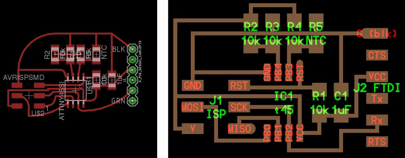
I had a much easier time with Eagle this time around, though I still have a long list of user interface complaints. Should've bothered learning the Eagle command line version... Here is my board design on the left, and Neil's on the right so I can double-check all the components and connections.
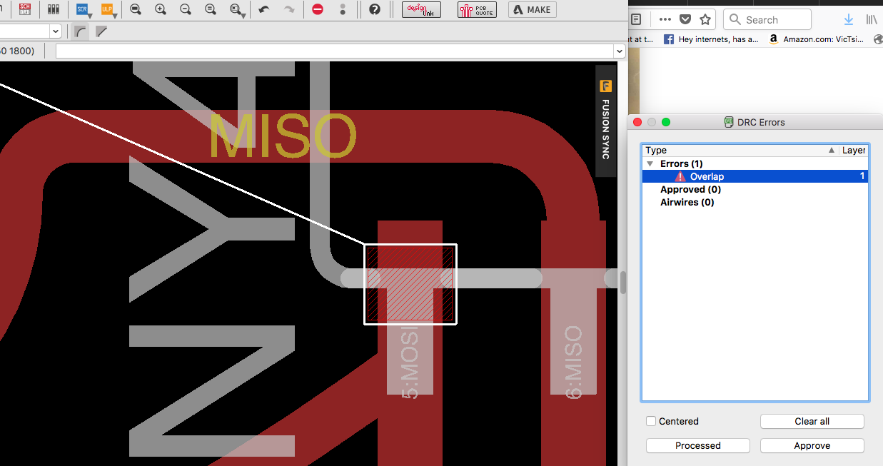
Upon running the design rules check, I ran into a strange problem where Eagle found an "Overlap" that was linked to something very far away from the surface of the board... I don't know why. I asked Tomás, who also didn't know what was going on, but ran a few test commands and then it disappeared. So hopefully this wasn't anything significant!
On my first pass milling out the outline, I broke an endmill-- it slipped down and snapped though I'd definitely tightened it. I'm sorry, TA's! I resolved to double-check both screws on the Modela next time. But the first board I milled didn't work anyway, since two of the traces were touching.
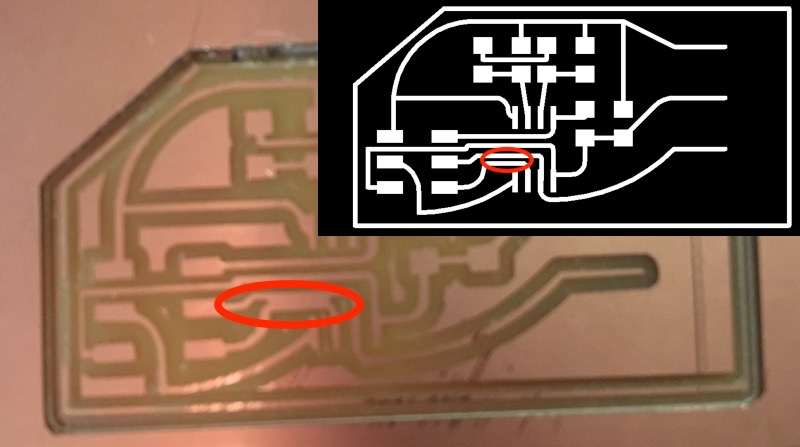
So I went back to the original design to move some things around, and I also rounded out the corners to keep them from peeling off the board. I made the traces a bit skinnier in the area under the chip where they melded together on the first board. The second attempt mostly milled out nicely! Except there were a lot of shavings under the board, which must have snuck under the double-stick tape and loosened the milled board from the sacrificial layer-- so it flew up at the very end and got snagged on the endmill. I quickly shut off the Modela and everything was fine. (Note #2: double-check the tape if I'm milling a couple boards on the same piece of material!)
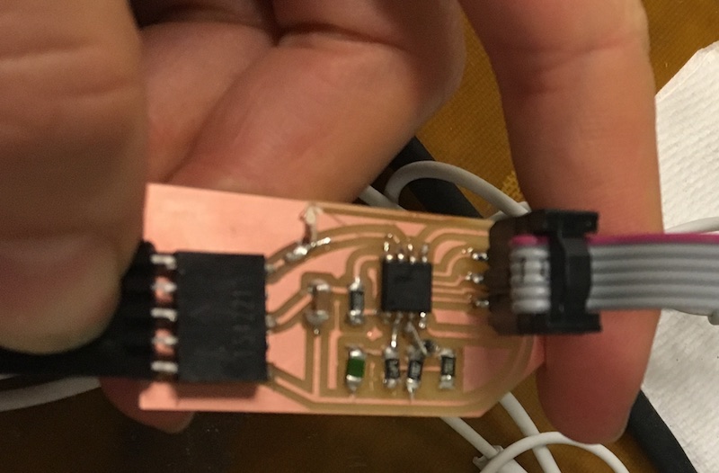
I melted off one of the traces when soldering, so I added a little jumper wire. Even though the soldering job is a little ugly, everything checked out with the multimeter so it was time to try programming... The female FTDI header wasn't the best idea, so I ended up doing a bit of a hack and sticking a male connector between my board and the USB cable. I ran some avrdude commands in the Terminal, and my board was recognized by my computer! Then I loaded this C-code onto my board, but I couldn't figure out how to load Neil's Python script to actually read the temperature. I kept running into inscrutable errors. Instead of spending hours Google, I just came to TA office hours and Thras sorted everything out within minutes. (Luckily he had a Mac, and had already spent hours Googling to make this work.) Turns out I had an old version of Python, and had to install a decently-long list of libraries before anything could run on my Mac.
For reference, here are Thras's commands so anyone with a Mac can also get their visual and/or scientific Python programs to load:
#install brew

/usr/bin/ruby -e "$(curl -fsSL https://raw.githubusercontent.com/Homebrew/install/master/install)"

# fix path

echo 'export PATH="/usr/local/bin:/usr/bin:/usr/sbin:$PATH"' >> ~/.bash_profile

# install tkinter

brew install homebrew/dupes/tcl-tk

echo 'export PATH="/usr/local/opt/tcl-tk/bin:$PATH"' >> ~/.bash_profile

# install python 2 with tk support

brew install python --use-brewed-tk

# install python 3 with tk support

brew install python3 --use-brewed-tk

# install packages required either in python2 (pip) or in python3 (pip3)

pip install numpy pyserial
Finally, I could run Neil's code to load up the temperature sensor, and then
run Neil's Python script and actually see my temperature sensor working!
At least, I think it was working... the numbers definitely changed when I held my finger on the
sensor, but not by as much as in the demo. Then I tested the sensor out with the heat gun and it didn't make much of a difference, which was highly suspicious. I wonder
if I burned the RTD while soldering or something? Or if mine just isn't very accurate?
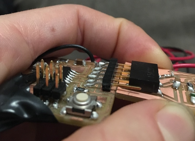
I then wanted to use this board as a daughter board for my ATtiny44 button-board, but I should've been a little more careful about the geometry; the boards bumped into each other before they could connect! Disappointed, I fixed the problem with a cable. The next step is to set up a feedback loop, so a cold reading from the temperature sensor can shut off the fan for my final project. After a cursory look at C, I realized I understood very little of it and resolved to try and get that working next week instead. Or perhaps I'll return to the good old friendly-but-oversimplified Arduino IDE...