Final Project
Week 3 thoughts: Let's make a freeze-dryer!
After chatting with my engineer friends Pweaver and Ned who are very conveniently my housemates, I'm starting to reconsider the
chocolate printer thing (as discussed in Week 1). It's actually a thermodynamics problem! Can I even get the chocolate to temper and then harden in
time to keep printing, or will I just wind up printing formless chocolatey puddles no matter how elegant my engineering?
Beno from Fab Lab Lima and Fab Lat came over and shared a different idea: making a cheap freeze-drier
for smallholder farmers in the Amazon, so they can preserve all the nutrients in their produce as soon as it's picked. We
entertained this idea, brainstorming potential designs.
Could we use a series of mason jars in a vacuum chamber?
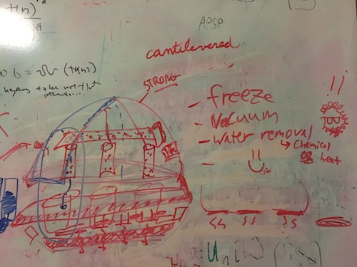
Beno was skeptical, and wisely suggested starting with a single jar before scaling up:
Week 8 thoughts: Let's make an evaporative cooler!
First of all, I'm not giving up on the chocolate printer-- I can instead try convincing my classmates to develop this printer for our machine-building week... Or, my friends at the Lab for Chocolate Science can help me out with this over IAP.
But for my project this term, I want something that involves more building and less tinkering with temperamental tempering. After thinking hard about Beno's project, I ended up chatting with my friend Alvaro who's also a Peruvian and a fellow in the Legatum Center where I'm doing my RAship. Alvaro has a fascinating, closely-related startup to Beno's: keeping fruits and vegetables cold on smallholder farms in Peru, so they don't rot while they're waiting for transportation, they don't need to be moved from a refrigerator to the trailer, and then they stay humid and cool durring transport. The whole distributed production question is closely related to my own research, and Alvaro got a budget to test out a cooling system next month so the timing is perfect. Also, I've been interested in this challenge for a while; post-harvest food loss is at the top of things that frustrate me about industrialized society (along with water-based sewage systems and corporate taxes on labor). I've been reading Finnish researcher Stephen Fox's writing about moveable microfactories, and the theory behind this idea of distributed food production. I've actually been interested about food transportation systems for years, and I'm excited by Alvaro's well-researched idea of evaporative cooling rather than full-on refrigeration. As a bonus, my mentor Kipp once challenged me to build a refrigeration system in a fab lab-- so this comes close!
Basically, I'm developing a swamp cooler conversion kit to turn any old trailer into a climate-controlled, produce transportation truck. The low-power-consumption swamp cooler (also known as an evaporative cooler) technology works by blowing air through a wet sheet of cardboard-and-cellulose material, which takes in heat from the surrounding air as the water evaporates-- thus cooling down the environment while keeping blueberries or asparagus moist (and therefore fresh).
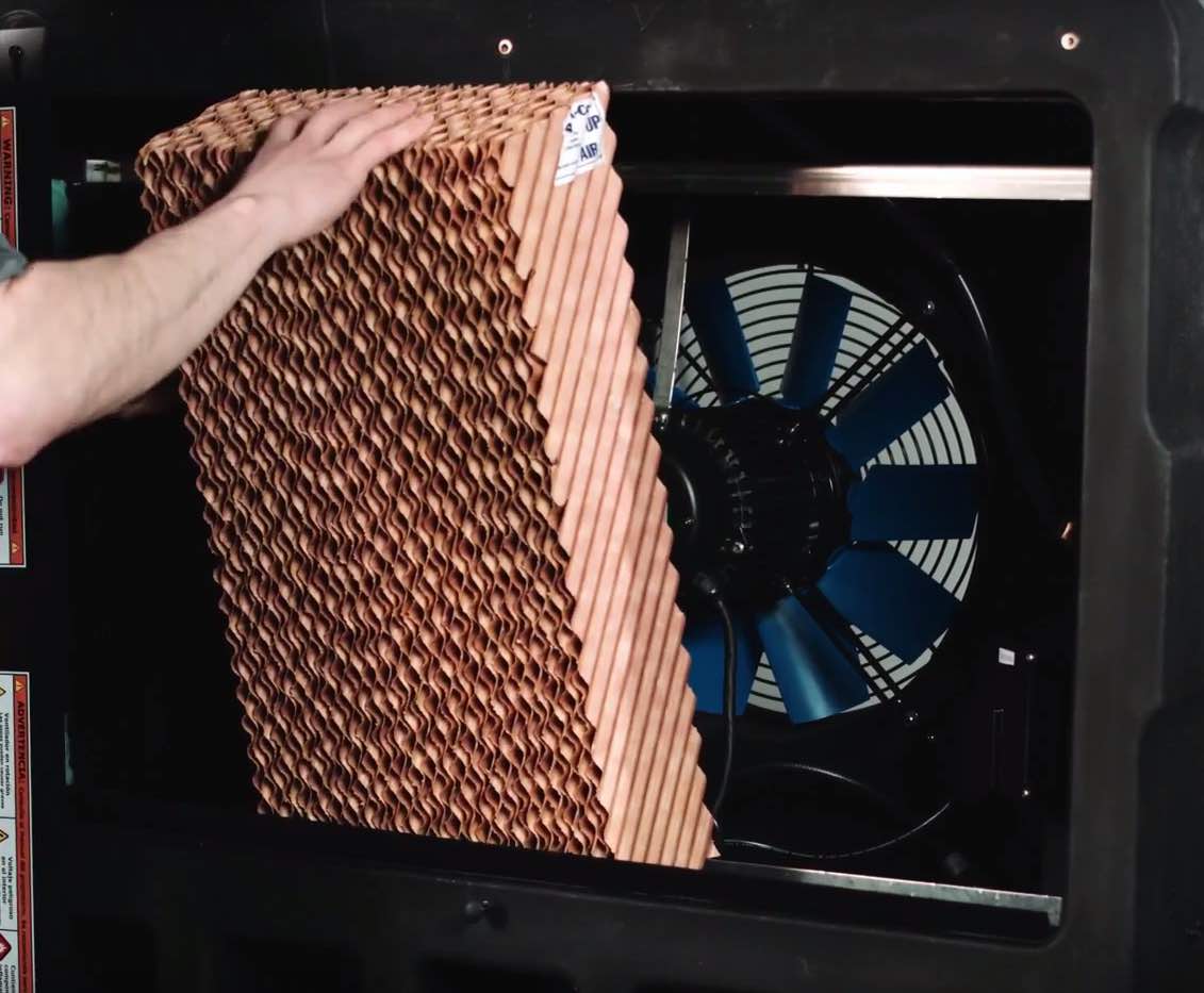
Here's a commercial version from the company Portacool, that isn't built to drive down the highway or specifically designed for produce:
Components
This project will involve the following mechanical components:
- Sheet of specially-coated cardboard: Alvaro already has a supplier, but it may be fun to try making this on my own during Composites week?
- Piping that won't leak during transportation (through which to pump the water up to the top of the cardboard)
- Rigging (to hold everything down)
- Containers to protect the electronic components and affix them to the walls (probably 3D-printed)
- Optional funnels (to route air through the right places)
- Tank or something to hold the water for pumping
- Fan (to dry the material)
- Water pump (to wet the cardboard)
- Temperature and humidity sensors (to measure the efficacy of the system)
- Optional electronic feedback loop (to automatically switch on/off the system when the temperature or humidity needs adjustment)
- Display for GUI: either computer, LCD, or mobile phone (to display temperature and humidity)
Week 9 thoughts: Still building an evaporative cooler
This week I finally got started on my project, by getting a solid state relay working with an AC fan and my ATTiny44 board. This led to some thoughts about how the electronics will all work out. First I have to decide how to power the system: should I use a wall outlet or a 12V battery? This choice may be determined by what pump and fan I end up using-- and then that plays a role into choosing whether to control the system through a solid state relay (for AC) or an N-Mosfet and/or regulator (for DC). All these electronics choices led me to make a sort of block diagram: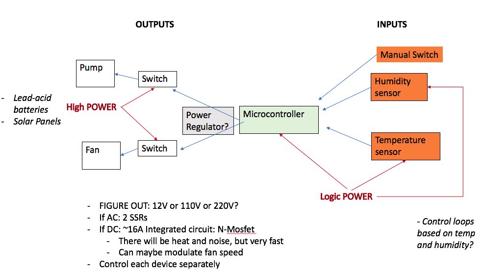
Week 12 thoughts: Built the user interface!
Week 13: Figuring out what I'm actually building
I'm running short on time now, so this week will require some very serious mechanical work and a bit more sorting out of the electronics. I need to get the humidity sensors up-and-running, connected to the web GUI, and also ideally add in some control loops so the pump stops when the humidity increases beyond a certain point.
On the mechanical side, we found a CAD model of a trailer and Abhi has been running some simulations to determine the airflow-- so we know whether funnels will be useful or not, and also how many humidity sensors we should install. We decided on four humidity sensors, or one on each surface of the trailer.
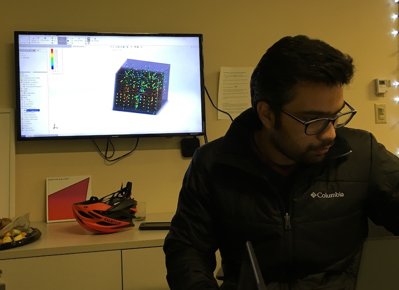
Here's Abhi with the model of airflow through the trailer and the stacked blueberry crates.
We've also got all the dimensions of the blueberry crates that we'll use to test out our system in Peru, so it will be easy to mill out some plywood on the ShopBot to mimic what the final, packed trailer will look like-- so we can actually test out the humidity and airflow in the real system.
To do this week: take apart the Portacool and see how their water pumping system works! Then, build a similar system out of composite materials and piping that won't leak while it's driving down the highway. Also, I need to get my accursed humidity sensor working so I can make all 4 of them and get all the code sorted out! Then I'll CAD some containers to house them...
Week 13: Programming time...
My humidity sensor is finally working!! Suffice to say I should've paid more attention to the datasheet and double-checked my pull-up resistors, because those are super important for both the SCK and SDA lines.
Next step is to figure out how to make 3-4 slave boards, and how to wire those together, and then how to log that data for viewing in the GUI. Turns out that the Softi2C library that I've been using for my ATTiny84 only works for master devices, so I'll need something else for my slave boards! Does this mean that I need a couple different libraries? Or can I figure out the C++ code enough to just write my own? This library looks promising,as does Christiana's example of successfully using ATTinys as both master and slave boards. Most of the other examples online seem to use an Arduino as the master, because it's much more compatible with existing Arduino libraries-- so this makes life more difficult.
Anyway, here's what I need my code to do from the master side:
And from the slave side:
- If you receive a ping sent to this specific board, send the humidity sensor data
- If not, do nothing
Week 14: Getting serious
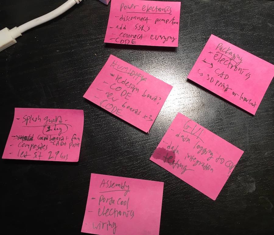
This week I started by dividing up my tasks into manageable chunks, and then writing them onto post-its so I can move them around and enthusiastically cross things off:
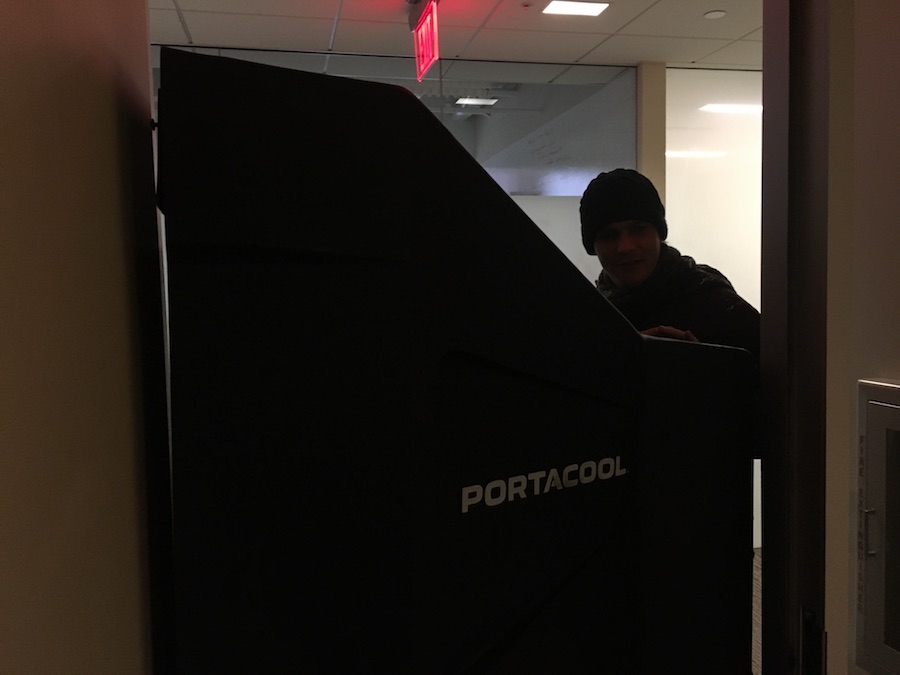
I also decided to use the Portacool as is, and just build a modification kit around it for the sake of time. So the first order of business was to get the Portacool into my lab. By some fluke, it fit through the doors with a full couple centimeters of clearance! NOTE TO PROSPECTIVE LARGE PROJECT DEVELOPERS: MAKE SURE THINGS FIT THROUGH YOUR DOORS. This could've easily been a disaster. Here's Alvaro helping me wheel it into the Legatum Center.
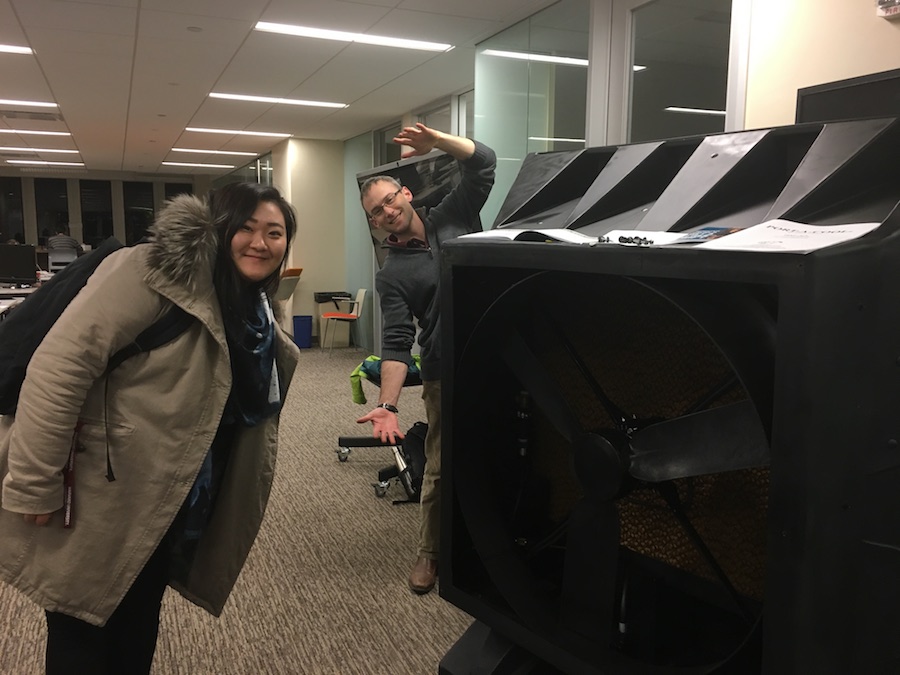
Here's PreserveAir co-founder Mike, with Legatum staff Julie who helped me pick up the unit from the loading dock. (Thanks, guys!) My lab-mates weren't very happy with this monstrosity in the office, so luckily I was successful in begging for a spot in the CBA shop just before the Legatum Center's major holiday party. (Thanks, John!)
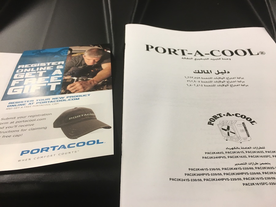
Portacool inexplicably sent their manual in Arabic, and promised us a free cap.
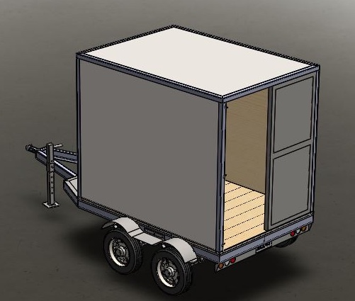
Please don't ask why we decided to prototype the whole thing in an full-sized trailer, and where we're parking the full 16ftx8ft trailer. Or how many professors we asked about using their driveways. Or how much clearance the trailer had when pulling into our parking spot at Pika. (Thanks, Pika!) Or whether this Portacool unit will even fit in the trailer. (That's a questions for another day. Say, Thursday.) Instead, let's talk about this lovely 3D model of a trailer, via Kennedy Kangwa on GrabCad, that I'm going to use for modelling how the system fits together!
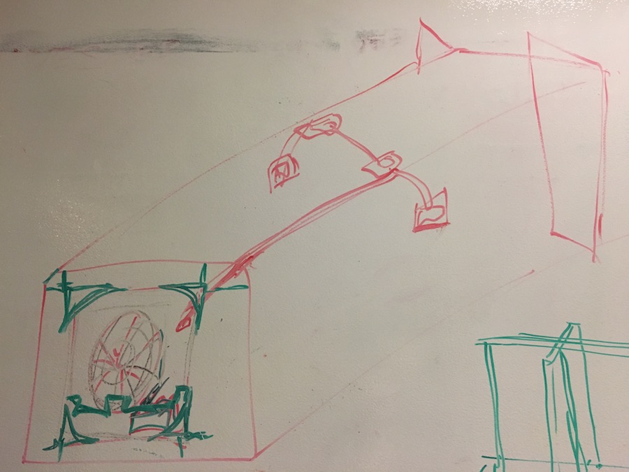
I haven't actually modelled it yet, though. Here's a vague whiteboard sketch instead, marking out the large mechanical components that I'm building (in green) vs what's coming off-the-shelf.
In particular, here are the mechanical things to build and how I will build them:
- Brackets for fixing the Portacool into the trailer: sheet metal (is it too late to get waterjet safety trained?) and/or plywood milled on the ShopBot. This part is exciting because it'll have to withstand the serious vibrations of a moving vehicle. Luckily Abhi is an automotive engineer, so he'll help with my designs before milling anything.
- Splash guard for the tank inside the Portacool: completed 1/3 of this with composites during composites week, but still need to make the rest. Perhaps a foam mold and a vacuum formed plastic sheet will be easier, faster, and more accurate? Worst case, I can spray the under-resined bits of the composite for waterproofing and make the rest of the splash guard this way.
- Flow breakers to go inside the splash guard, to keep the water from splashing about too violently: to be 3D printed. I hadn't even considered this until Mike and I started brainstorming things that can go wrong when driving down the highway, and large sloshing bodies of water are definitely on that list.
- Enclosures for the humidity sensors: to be laser-cut out of acrylic, and then screwed into the wooden interior of the trailer. These should be pretty straightforward once I finish milling out my circuit boards.
- Cables: where will all the cables go? How will they all be packaged together?
Bill of Materials
- The Portacool Cyclone: $2000 (or you can easily get all the components more cheaply and assemble it yourself, if your friend Alvaro isn't dying to spend his grant from the MIT Sandbox on a mega cooling system (thanks, Sandbox!) Here's an easy DIY swamp cooler that's much smaller for around $20 of materials.
- A trailer: ~$2000 off Craigslist (beware of Craigslist trailer scams! Apparently those are a thing.)
- around 1kg of bio-based resin for composites: ~$20-30 depending on whether you buy in bulk
- several meters of burlap fabric for composites: free if you use scrap materials from the rest of the class, or ~$40 for new < a href="https://www.rockwestcomposites.com/materials-tools/fabrics-pre-pregs-tow/ekoa-flax-fiber/13055-d-group">flax fiber from CBA's fancy composite supplier Rock West
- Acrylic for electronics enclosures: ~$3
- 3D printing filament for flow breaker: ~$10
- Electronic components: ~$7 total if you only make 2 boards, including standard components orderable off of Digikey: ATtiny84, LED, resistors (1k, 4.9k(x2), 499K, 0/vias (x4)), 6-pin ISP, 4-pin ISP, FTDI header, 100nF capacitor, 20mHz resonator, 1uF capacitor, 5-3.3V voltage regulator, and the HTU21D humidity/temperature sensor ($2-5 each)
- Solid-state relay (SSR) that accepts 3V+ on one side and 110-220V on the other: ~$30
Finally, let's make sure that I'm completing all the stages of the final assignment:
- 2D design: circuit design in Eagle, sensor GUI
- 3D design: splash guard, electronics housing, flow interrupter
- additive: composites, 3D printing flow interrupters
- subtractive fabrication processes: laser-cutting electronics housing and cardboard mold for composites
- electronics design and production: humidity sensors and SSR control loop to shut off the pump when the air gets too humid
- microcontroller interfacing and programming: web GUI to display sensor data
- system integration and packaging:
stick it all in the trailer, and ensure that it holds together on the highway without ruining any blueberries?Errrr this didn't entirely happen, partially because the trailer was too small and partially because I spent way too long attempting to get serial communication working between my sensors. I settled on a single laser-cut electronics box as a proof-of-concept, and some cables that I kinda tied together. Zip ties came in handy.
Final Electronics Push
This week was full of electronics failures-- my totally functional board suddenly stopped reading the sensor, so I de-soldered and re-soldered it on better, but then the microprocessor stopped working spontaneously. Belatedly, I realized that I might have just had my pins swapped in the code. So I took the ATTiny off, found a broken trace, and fixed that with a jumper cable-- but it keeps refusing to function even though everything was perfect the other day. I made a whole new sensor board which works great, but I still can't get my bloody original board to work again! And I need two boards to test out the code... so I went and just milled a daughter sensor board, but then I couldn't get that one to work either-- although it's likely a coding problem.
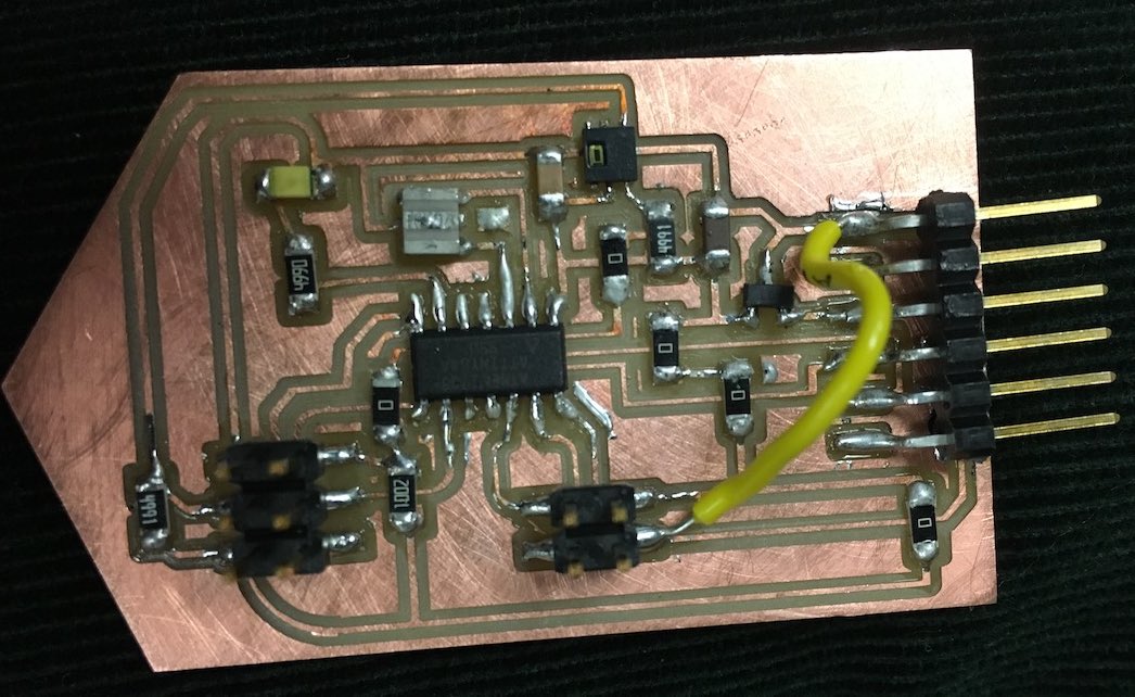
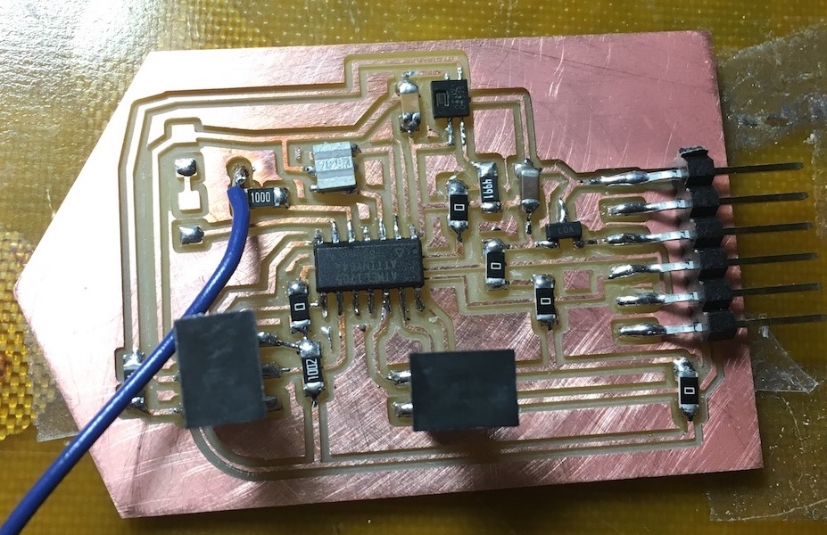
Here's my single functional sensor board and its layout (that's a 4.9K resistor on the far left, I ended up taking out the 1k resistor before the attached wire, and I attached a second wire to ground for the SSR):

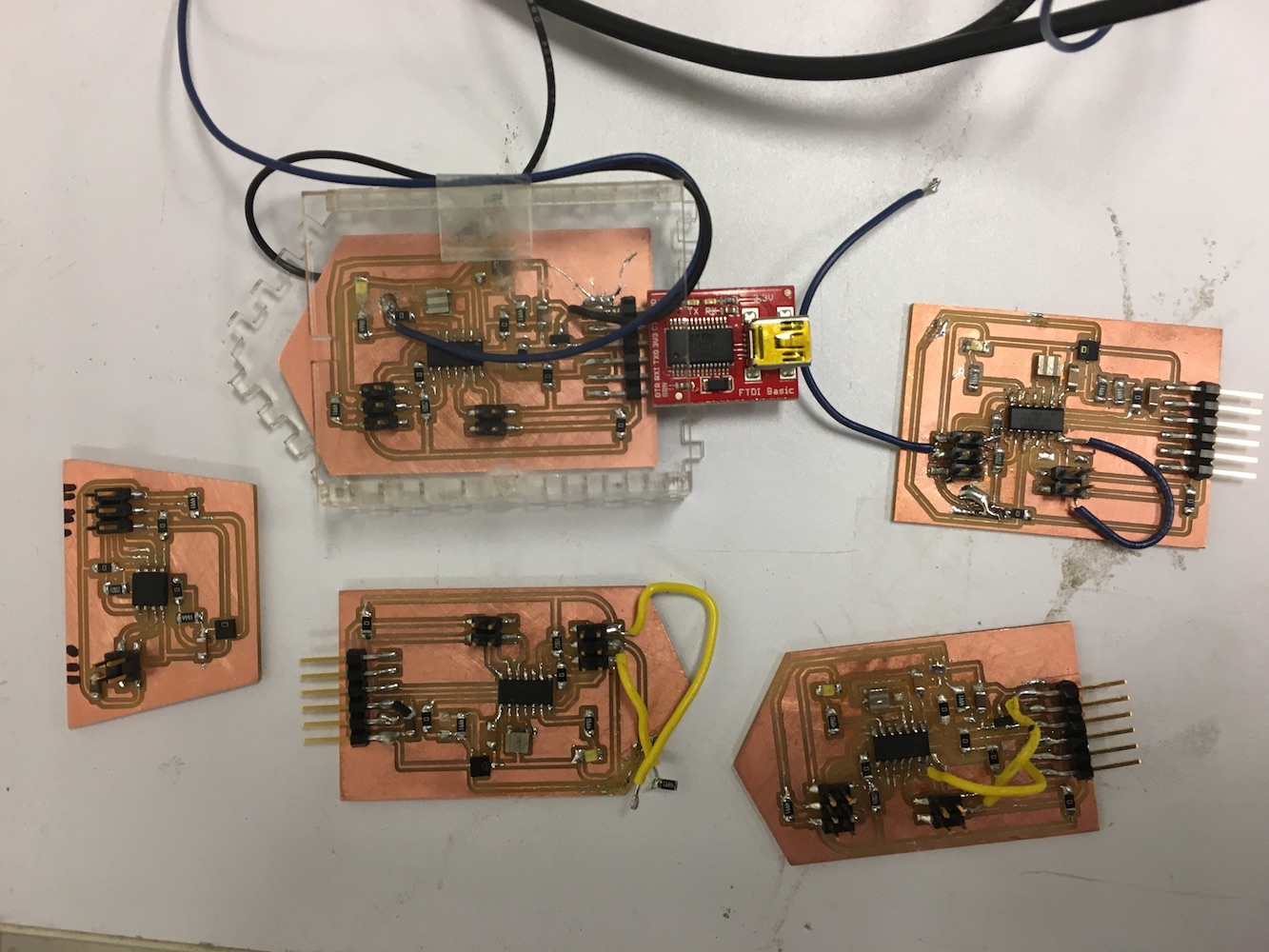
Here's my sad collection of semi-functional sensor boards, with the 2nd sensor daughter board on the left which would probably work if I got more help on the code:
Ahhhhh I'm sure I could get a second sensor up and running in another day or two, but the combination of I2C (to talk to the on-board sensor) and then some serial protocol for the two boards to communicate together just turned out to take too much experimentation time. (It's hard to learn C-code from scratch through trial-and-error, but I've learned so much!) To make matters worse, my FabTiny turns out to be inconsistent in sending/verifying large packages of code-- so I spent a solid number of hours trying to debug boards that weren't actually broken before realizing that the problem wasn't "no serial device attached" but rather it was all my FabTiny.
Just when I thought I’d figured out I2C, Sam informed me that it’s not the best idea to use this protocol over long wires because something about capacitance messes up the data transmission! So I then spent a while trying to figure out serial bus communication, using the RS-232 protocol recommended by Neil. But that’s complicated, and it’ll take me at least a couple more days than I have to actually learn C. So I tried to do the lazy and ugly thing and just have my boards spitting out sensor data indiscriminately in JSON format, then the computer will read each one as the data comes in, and it’ll identify it by the particular tag (D1 or D2) that each sensor board encodes into its JSON. I was then hoping to some Arduino libraries and not have to learn all the C from scratch...

But I couldn't get even the basic code to work either, sadly. I tried debugging the board (no apparent problems), and then realized that it was probably some Arduino compatibility thing and anyway I'd exceeded the time that I'd allotted to solving the second sensor problem by at least a day and a half. Here's the sort of garbage I got when I tried reading from the daughter sensor using the spew-out-data-indiscriminately code and the 4-pin header.
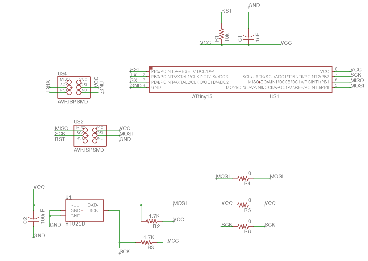
This is the daughter-board I'm trying to use (click to enlarge). Can you see any problems?
Here's a different sort of garbage, when using the 6-pin header and some modifications to the daughter code. I couldn't get my call-response I2C code to even recognize the daughter board.
Or the serial read test, although that one may involve looking around in the header files to try and re-define the pins.
I still feel like I'm just a few minutes away from getting it working, and there are lots of possibilities available and various tweaks to fix things. The problem is that I'll likely need to do some bit-banging to get the pins properly wired up, and also I can't just test with plug-and-play Arduino code because my SDA and SCL pins are different on the ATtiny. Here are some of the options for getting multiple humidity sensors working:
One of these should eventually work, unless my daughter board is broken, in which case I can make another one.
My next electronics project was thankfully much more straightforward: getting my mini-fan to turn off when the humidity gets too high for blueberries. According to this document from Louisiana State University, the ideal relative humidity for blueberries is 90-98%-- so I set the turn-off point at 100%, which conveniently is a bit under the humidity of my breath which is around 110-120%. This makes it easy to test the feedback by blowing on the sensor!
I already got my solid-state relay switch working back in Output Devices Week, so it was a pretty easy matter to modify the if/else statements in that code to send a low voltage signal to turn off the fan powered by the wall outlet. The hardest part was getting the extra wires onto my humidity sensor board, as I soldered some pins together when trying to add the ground wire and then shorted out the powered wire when soldering it into the via I'd drilled on my board.
At least my simple Humidity > 100 code worked beautifully... except for the fact that the voltage regulator meant my high voltage was down from 4.something to 2.6V, which wasn’t high enough to trigger the SSR! The SSR's in the shop require 3-32V, but I fixed this by taking out the 100 ohm resistor that someone had told me was a good idea to include in my previous SSR board. Then the high voltage came back up to 3.2V, allowing me to properly turn my fan off by breathing on the sensor. Finally, some success!
Interfacing
Thanks to the Interfaces Week, I had a lovely GUI to build upon-- all that remained was the totally nontrivial task of connecting this up to my board to use real sensor data. Luckily pySerial is very well-documented with a plethora of examples online, so it wasn't too hard to get a basic demo of reading serial-port data from my sensor board.
Getting the right data from my sensor in the right way turned out to be much trickier, but luckily my brother was around to help debug.
I kept the Arduino sensor-reading library, which admittedly isn't the most elegant way to do it since it's better to do all the data parsing in Python, but I ended up writing a program for the microcontroller that outputs data is JSON format-- so it's easy to just pull into the Python script and send to the GUI. This only took a few hours to sort out, but then Albie insisted on spending a good number more hours making the code more robust by adding threading. This became a confusing and nitpicky trial-and-error game to figure out what classification of values we should use, but once again Google proved invaluable. Although threading doesn't make much of a difference for this proof of concept, it will definitely be useful once I add in more than one sensor. Here's everything working, with Albie on Skype in the background having just solved a bug caused when I mistakenly substituted some tabs for spaces. Let it be known that he did much of the debugging by looking at my screen via video-chat on my phone, while driving over the notoriously reception-poor Golden Gate Bridge.
Final Mechanical Development
I had 1/3 of a totally functional splashguard from composites week, which is a decent proof-of-concept for the full splashguard. Since I also had a law final to study for, I decided to spiral down and stick with the cardboard mockups/molds of the rest of the splash guard. The other ones were somewhat tricky to figure out how to make them removable, given all the irregular protrusions around the interior of the Portacool. Here's the full set inside.
And here they are outside of the unit. They look flimsy now, but they'll make decent molds when I fill them with more cardboard and then cover them in plastic wrap before making more composites. As before, I was very glad to use cardboard for this prototyping so I can easily check all the tolerances. I thought about using the vacuum former to make faster and lighter splash guards, but as Mike pointed out these might be too light and they could just float and splash around during transport.
Then it was time to make a flow-breaker for the inside, so the water wouldn't slosh about too much. I started with some sketches.
Next I made a cardboard model, and decided it needed to be much bigger to really break up the flow.
I CADded up a parametric model, and added a bonus fifth wing because I could. I'm definitely getting the hang of CAD now-- instead of struggling for a while with strange parameters and then getting everything skewed, I started out with one wing and then iterated it in a circular pattern.
When the model was ready to go, I loaded it up in the Wox Sindoh printer. These printers have an obnoxious chip in the filament, and I kept running into strange filament errors because it turned out that someone had left a "purple" chip in while loading the spool with red filament. Finally it started printing out smoothly.
It came out just as I modelled it! Then I sprayed it with water and glued it down to the composite with Gorilla Glue, using a few heavy metal objects as impromptu clamps.
Gorilla Glue worked well, and also it's waterproof. Super robust!
Fitting it all together
Remember the lesson about making sure that your large things fit into doorways? Yeah, the Portacool is an inch too large for our trailer...
Abhimanyu and I went over to Pika with some measuring tapes and lots of enthusiasm around CADding up some brackets to fit the Portacool into the trailer, and then we discovered that there's an inner doorway that's both shorter and narrower than the Portacool. What to do now?
We walked over to CBA together to double-check my Portacool measurements (I was fairly accurate, sadly), and then we brainstormed how to slice bits off the sides so the blasted thing will fit where we need it. I felt kind of bad about destroying the unit's fancy exterior housing, so I decided to shelve this part of the project and focus on my electronics instead. Here's my CAD model of the Portacool, from back when I thought this would be useful for building brackets and such. Also, I didn't hear back about whether I could actually park our trailer outside the Media Lab until the last Friday of classes, and even then the answer was a sort of "probably, but you might get a ticket if the cops are around." Furthermore it seemed awkward to have my final project outside (in below-freezing temperatures) when everyone else would be nice and warm on the 6th floor. Even more awkward would be setting up a humidifying cooling system in the middle of winter and then hoping people come in to visit it. So I decided to focus on my electronics instead, which... as mentioned, wasn't actually the best idea for getting things accomplished, but at least I learned a lot.
Frustrated by the nest of dangling wires and disconnected gadgets, I decided to make at least one nice electronics housing. I followed this excellent video tutorial and learned how to make some finger joints for my acrylic box-- and I was careful to model everything parametrically in case I misjudged the kerf.
We had a bit of trouble getting things laser-cut on the Epilog, so here were the final settings that George helped me configure.
I did misjudge the kerf so it didn't all snap together neatly after laser-cutting, but superglue ended up working almost as well as a (more elegant) mechanical fixture. Note to self: funky shapes may seem like fun, but they're a hassle to fit things around!
Final Project Questions
what does it do?: This is a proof-of-concept for a climate-controlled trailer, using evaporative cooling to keep produce fresh during harvest and transport. Specifically, there's a temperature/humidity sensor that outputs to a graphical interface and also turns off a fan (or eventually the Portacool pump) when the humidity rises above some threshold, and a fully-designed (though not fully-built) splash guard for the bottom of the unit.
who's done what beforehand?: Alvaro bought the Portacool, which has already been designed as a commercial evaporative cooler. Refrigerated trailers have definitely been around for a while, though swamp coolers for food transport are less common.
what did you design/make?: The splash guard (composites over Epilog laser-cut cardboard mold) with (Wox Sindoh) 3D-printed flow breaker, the electronics (milled on the Modela and programmed through the Arduino IDE), the electronics box (laser-cut on the Epilog), and the web GUI (Python, Flask, CSS, and Javascript)
what questions were answered?: Can I make a functional electronics board from just reading the datasheet for a sensor? (Yes, eventually.) Will the HTU21D sensor work out of the box, and be sensitive enough to act as a decent humidity regulator? (Totally.) Can I build a robust climate control system for a trailer? (Yes, also eventually.) Will composites work as a robust splash guard for the interior of the Portacool? (Definitely.) What's the best way to read data from two sensors that have the same serial address? (Likely pinging them through a Python script, but TBD.) Will anything ever fit? (Unlikely.)
how was it evaluated?: I've got one sensor that I think is reasonably accurate and a control loop to turn off the cooling system-- which is the bare minimum for a functional climate control system! I've also got a user-friendly GUI, even if only one of the sensors is currently providing data. Nonetheless, I really need to stick everything into the trailer and drive down a rocky highway with a bunch of blueberries to see how they fare and whether the splash guard works out...
what are the implications?: I learned so much about electronics, as well as the basics of designing and building mechanical things! I feel capable of making a CAD model from scratch, and therefore won't be limited to paper and pencil in the future when sketching out ideas. I also learned a lot about managing expectations and how to scale down a project to a manageable size, while letting go of the fact that I can't quite accomplish all the things I intended. On the project side, it seems like composites are definitely the way to go for the splash guard (although they're on the pricey side), and the HTU21D sensor will serve our purposes well. I could totally make a Portacool from a pump, a fan, and some PVC... if I had more time. Fabbed circuit boards have some issues, but they're awesome for rapid prototyping and creating functional electronics. All in all, this is a decent beginning for a much larger project and-- after catching up on sleep-- I look forward to sticking it all into our trailer over IAP! Eventually Alvaro wants to prototype in Peru, so I'll be in touch with Beno and my other fab friends about whether we can use their lab to remake much of the project...
what's next?: There's tons more work to do before this is ready to cool blueberries, and tell you how the blueberries are doing as you drive.
- Get the daughter sensor board working, and then make 2 more of them! I have one board. I know how it should connect. I'm just missing functional code...
- Build more composites (or something else) out of the cardboard splash guard molds.
- Figure out how everything fits into the darned trailer.
- Redo the acrylic cases so they snap together mechanically, and then make more for all the sensors.
- Figure out the cable layout and packaging inside the trailer
- 3D print more flow obstructors for the splash guard
- Wire up the actual pump to the SSR
- Add solar panels to the system (long-term goal)
Putting it all together...
Unfortunately I was sleep-deprived and forgot to take a video, so please just imagine the tiny fan in the corner of the Portacool spinning, and then stopping when I breath on the boxed humidity sensor. Picture one gauge on lovely user interface (for a hypothetical trailer that actually fits the Portacool) moving up and down with the temperature and relative humidity of my one functional sensor, as the Python code runs alongside in the terminal, reading the sensor via serial which is connected to my USB port:
Files
- To test out the GUI, download this .zip file and run the temp_app.py script. Plug in your humidity sensor and open your web browser to the local host at http://127.0.0.1:5000/ to see the sensor GUI.
- Load this code onto the sensor motherboard to both turn off the power at high humidities and to read the sensor data.
- You'll need to download enjoyneering79's HTU21D library and luetzel's SoftwareI2CMaster script in order to get the sensor code working on an ATtiny84.
- Here are the Eagle files for the final sensor board. The via on this board was connected to a power cable that goes into power on the SSR, and I added another cable to connect to ground on the SSR. The other side of the SSR is ideally connected to the pump, although for the demo I hooked it up to the small fan I used in Week 9.
- And the image files to cut your own board: