Week 13: Networking
This week, I tried to use I2C communication to get four different HTU21D humidity/temperature sensors working in parallel.
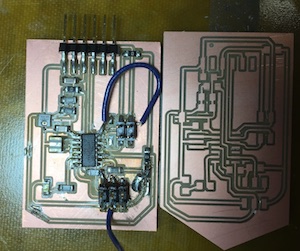
As evidenced from this special malfunctioning circuit board, I failed spectacularly in a variety of exciting and highly educational ways. In this early hour of Wednesday morning, I think I finally figured out the latest bug-- but I'm out of time for this week, so I'll just update this page once I get everything working. It all has to work for my final project, anyway...
I started out with a brainstorm: I want my four sensors to be interconnected (without interfering) and they all need power. Options:
After some consultation, I decided that the most robust option was likely the first: physical connections. The first step was to get an ATTiny chip talking to a single sensor, which could be an initial test of the I2C communication protocol since the sensor has its own built-in chip. (I could've used PWM to read the sensor data, but everyone on the internet seemed to use I2C and I don't know enough to write the code from scratch!)

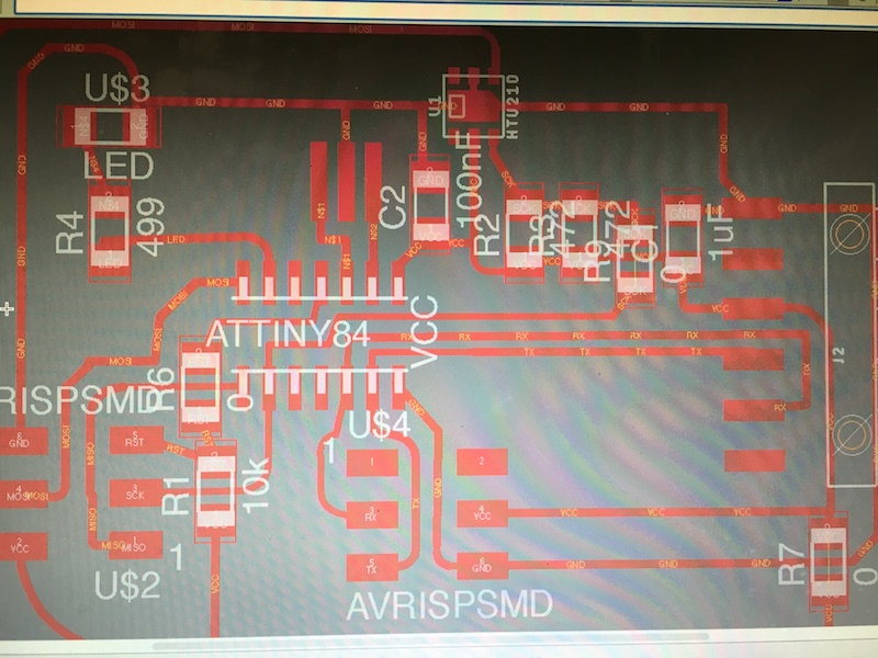
So I designed a board in Eagle following my sensor's datasheet guidelines: I needed 2 pull-up resistors and a capacitor, and one sensor port had to be connected to SCK. I also added a 20MHz crystal to help with the timing, and an LED to help with debugging.
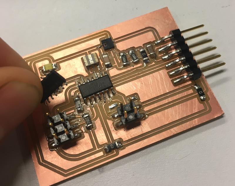
I designed, milled and stuffed a decent-looking board.
I was excited to get started because Sparkfun promised me that this sensor was easy..
...but then I kept getting Serial errors through my Arduino IDE. I installed Adafruit's humidity sensor library, but it took up too much memory on my ATTiny44 chip! So then I tried the Sparkfun sensor reader, but I kept getting a cryptic C error. Finally I found another demo from enjoyneering79, which uses luetzel's SoftwareI2CMaster library, but those were ALSO too big! Argh! I commented out a bunch of the code, and even tried modifying the library files (note to self: never do that again)-- but it still used 5262 bytes out of my meager 4096 bytes. I was about to give up all hope when I decided to look up whether there’s another ATTiny chip in the CBA shop with the same footprint and even more space.
And there is: the ATTiny84! It has double the memory! Why didn’t I think of this earlier? So I de-soldered my ATTiny44 and swapped in an ATTiny84, but in the meantime I burned my LED and maybe other components on the board. So I fixed it.
But then the serial communication wasn’t working— I kept getting the error "the selected serial port does not exist or your board in not connected." What was going on? I realized that the best way to test out serial communication was with some serial code that I know works, so I loaded up Neil's hello-world serial printing code, which I modified slightly to be able to load it up in the Arduino IDE. As it turned out, testing the serial port was a really good idea-- because something in my board was fried. Also, Enjoyneering79's HTU21D library recommended using the SDA pin on my ATTiny, and it seemed like a good idea to follow their advice because this was the only code that had an obvious way to change the pins.
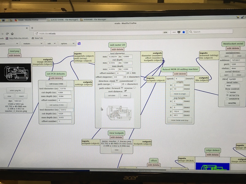
My traces were also way too small, so this gave me a good excuse to fix the milling settings and make a better board for Mark 2. I designed, milled, and stuffed a second sensor and ATTiny84 board, this time connecting my sensor to both SCK and SDA.
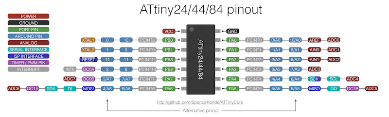
Here's a helpful diagram for sorting out Arduino pins on the SCK:
This board also had some strange serial connection errors, so I went back to my serial test code to see what was going on. It worked every 2 out of three times, and the board seemed to work with Arduino's blinking-LED code, so process of elimination showed that it might be my Fabtiny programmer. Turned out some of my classmates were also having some timing issues with their own DIY programmers, so I went down to the CBA shop and tried out the AVRISP MKII. Suddenly my board's serial port worked seamlessly!
It was finally time to test out my sensor. I still couldn't figure out how to switch the pins from the Arduino defaults on Adafruit's example or yet another Arduino example from jrowberg and PaulStoffregen's sensor library (which meant that I couldn't get either of them to recognize that I had a sensor installed), and the Sparkfun library kept giving me errors, so that left the code from enjoyneering79.
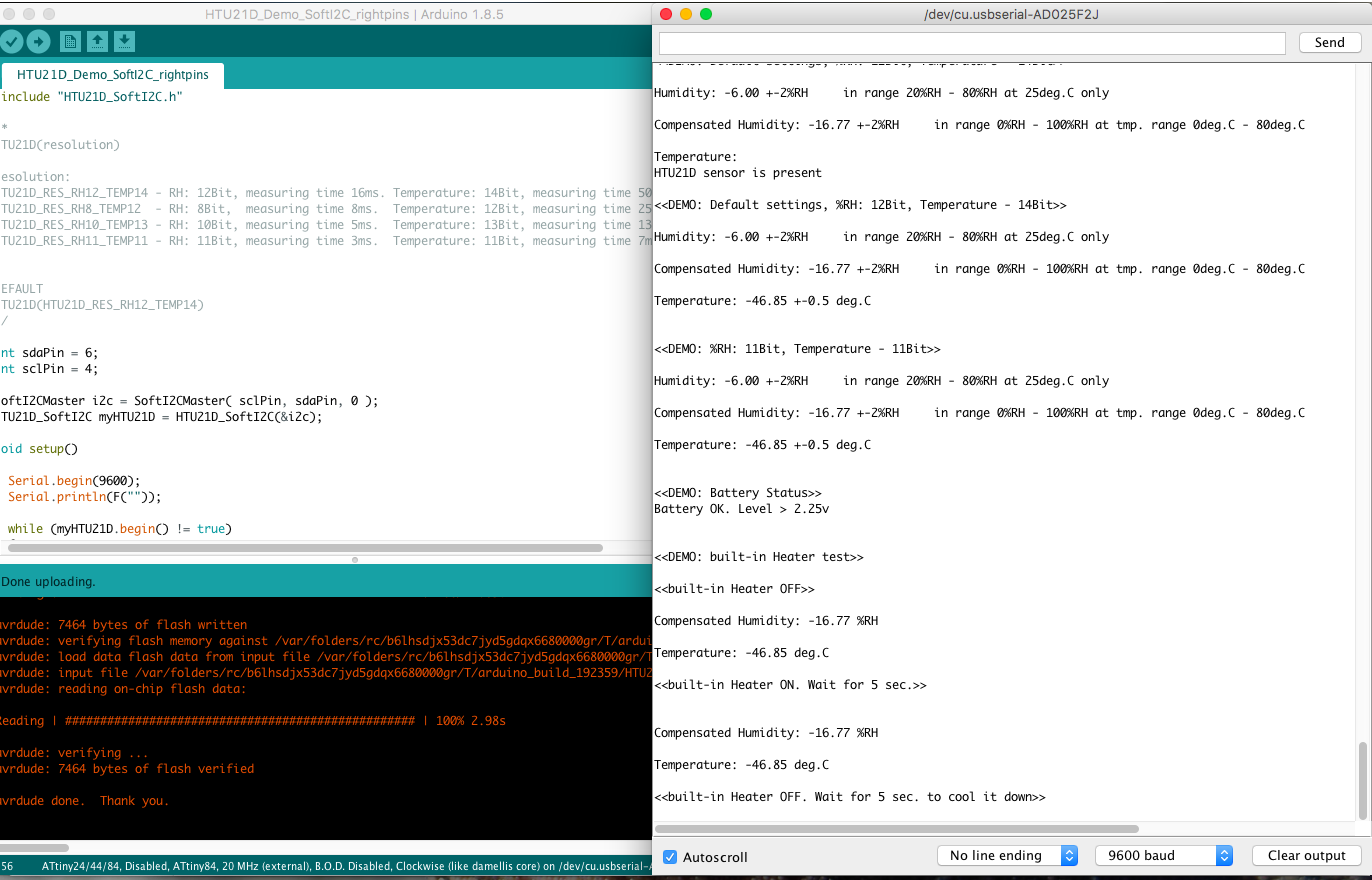
It took me a while to get it up-and-running, but finally I switched from my snazzy FTDI-to-miniUSB converter to the lab's FTDI cable and everything started working again. (Tip: double-check all USB connections, and burn the bootloader beforehand just in case something got corrupted becaue cables weren't properly connected.) Except it wasn't actually working-- the chip recognized that there was an attached sensor, but the sensor kept reading negative values for everything.
What did I do wrong this time? With the code loaded, I checked the oscilloscope and saw some pretty normal-looking waveforms when I measured the signal between SCK and SDA. Better yet, these waveforms shifted when I increased the sensor's temperature (by touching it) or humidity (by breathing on it):
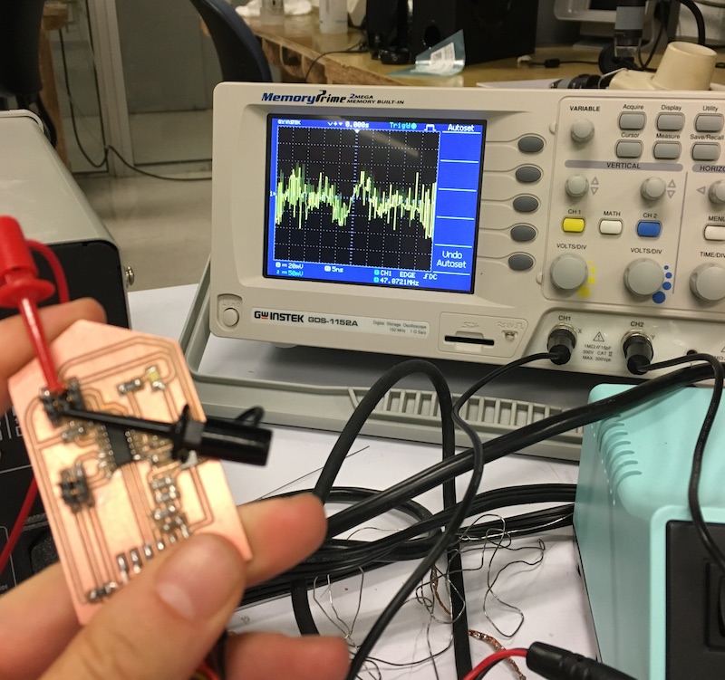
For good measure, I loaded up the Adafruit code that wasn't recognizing the sensor-- and the waveforms were completely different, which indicated that the code I was using was likely not the problem.
So something was wrong with the data reading. With lots of help from our undaunted TAs Thras and Allan, and a last-minute call to Indy (my friend's CTO) who just remotely debugged my sensor from Berkeley, CA, I made a list of everything that might have happened:
Something was wrong in the code unlikely, since the waveforms seem decentSomething was wrong with the serial port nope, since Neil's "hello world" works fineThe Arduino clock settings didn't work for the ATTiny I set the Arduino IDE's clock settings, and Indy looked over the code and said this wasn't an issueThe Arduino baud rate didn't work for the ATTiny I went through all the possible baud rates and the problem remained. (and baud rates lower than 4800 just returned gibberish)
It had to be one of the last two... Indy looked over the datasheet and asked me how much power I was feeding into the sensor. The answer: about 5V, which is outside of the sensor's sweetspot of 0.3-3.6V. The solution was on the bloody datasheet this whole time! Because the Arduino can adjust the voltage easily, this never occured to me. Even though I'd poured over this datasheet to design the initial circuit. Finally, problem hopefully solved.
I came very, very close to getting some I2C communication between the chip on the sensor and my ATTiny84. I've even designed the other 3 sensor boards, but it's good that I didn't mill them since I need to sort out this voltage issue first. Check back next week to see these humidity sensors finally working!
- Helpful links for this week:
- https://www.arduino.cc/en/Serial/Print
- http://fab.cba.mit.edu/classes/863.16/section.CBA/people/Costa/week13/index.html
- https://learn.sparkfun.com/tutorials/i2c
- http://www.electronicdesign.com/communications/what-s-difference-between-bit-rate-and-baud-rate
- https://www.arduino.cc/en/Reference/WireBeginTransmission
Update
Yay, they finally worked! I2C communication: achievement unlocked. See my final page for more details.