Week 9: Output Devices
So I finally decided to get started on my final project: an evaporative cooler that can fit into a trailer for cooling down produce. This week's goal was fairly simple: control a generic fan using my own circuit board. Once I get a fan working, it'll be easy enough to attach a pump-- and then I'll add sensors and a temperature-based control loop during the Inputs week. The main thing to worry about this week is not getting electrocuted, since I'm probably using high currents.
The first step was to figure out how I wanted to control my fan. I initially looked into H-bridges, considering the possibility of
milling a new board with two H-bridges to control the power output to both fan and pump. Then, my friend Pweaver helped me
come to the conclusion that a homemade H-bridge would be both unnecessarily complicated for my project and also potentially dangerous
for high-powered electronics.
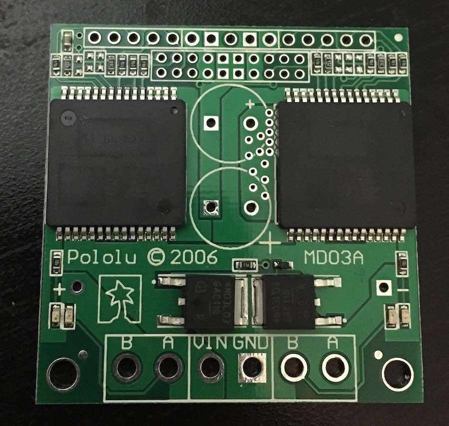
Pweaver loaned me this Pololu dual H-bridge that he had leftover from a power electronics class project, and pointed out that the board is so thick because it's built to be both semi heat-resistent and safe for high-powered things. If I wanted to mill out my own board in the CBA shop, I may need at least two layers. I found a number of students from previous years who made their own H-bridge boards (mostly for low-powered things like LEDs and speakers), and thought about it for a while before deciding to pursue a different path.
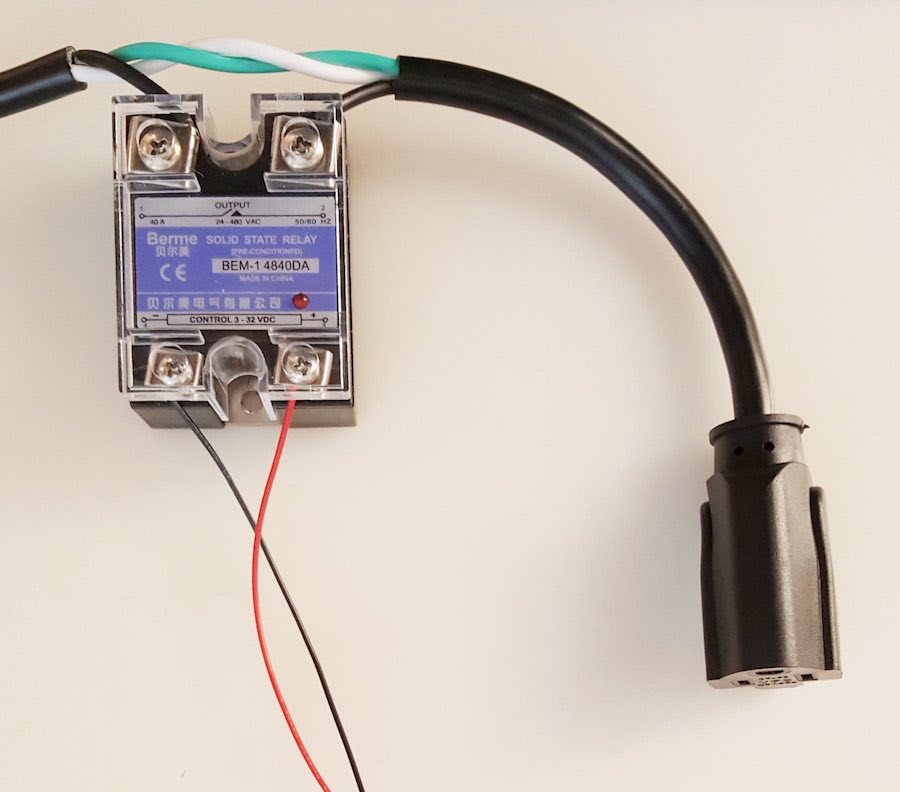
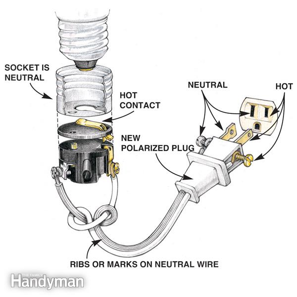
I looked around more previous students' pages, and found Matthew Arbesfeld's helpful description of how he used a solid state relay (SSR) to control a water pump with the button-and-LED board that he milled during Electronics Design week. I realized that this was indeed a better option, since SSRs are designed to safely control wall-powered AC devices (like my mini fan and most of the water pumps available online) with a low-voltage DC current (like my ATTiny board) acting as a switch. There's a mechanical separation between the two leads of the hot wire, so there's no danger of overheating a circuit board if everything is wired correctly. On the downside, it only allows for binary on/off inputs to my fan. This photo is from Neil's class page, and clearly depicts the proper wiring of a solid state relay. While an H-bridge would allow me to control the speed and direction of the fan (or pump) motor, this isn't actually necessary for my project: the fan and pump just need to turn on and off based on the room's temperature, and they can always run at the same optimal speed.
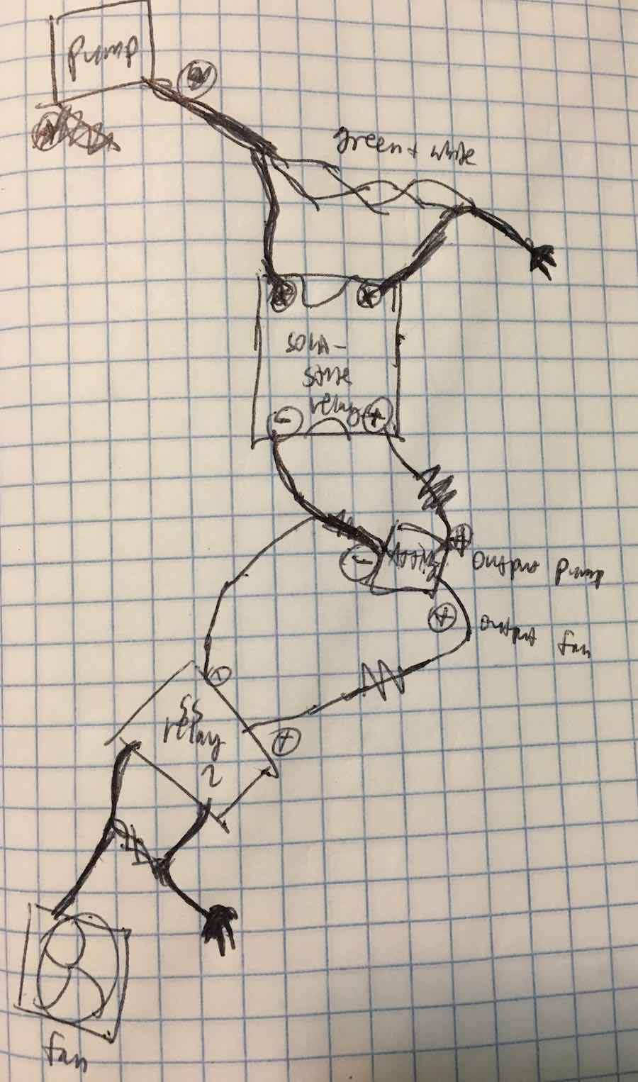
I consulted with our wonderful TA Will (who held office hours on Sunday morning because he's amazing) about the best way to connect the pump and fan to my ATTiny circuit board using an SSR. Here's my rough electronics diagram, though (after more consultation) I might switch to an N-Mosfet instead of an SSR if I go with DC rather than AC devices.
First I prepared my ATTiny board for some modifications. Following Matthew's design, I decided to see if I could just replace the existing LED and 500ohm resistor with a 100ohm resistor attached to power. I planned to solder the ground cable directly to the ground pin on the port that connects to a USB. I easily de-soldered both LED and small resistor from my board using the heat gun, holding the unwanted components with tweezers until the board fell away as the solder melted. (This is an excellent technique!)
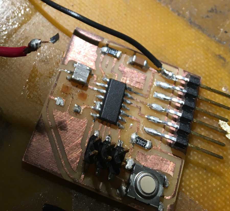
I soldered on the ground cable with no trouble, and then ran into all sorts of trouble soldering on the power cable to the copper pads. First I soldered two pins together on the ATTiny, then I melted the glue or something and the copper pads just peeled off my board.
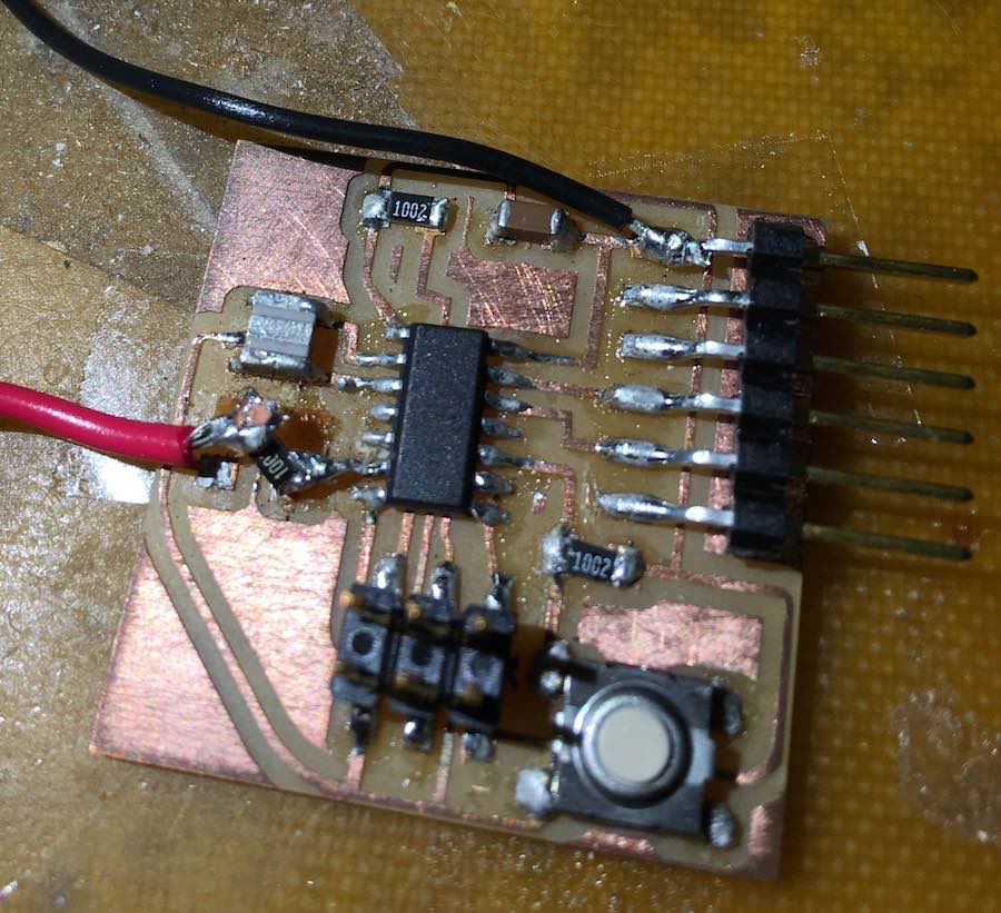
I should've started soldering with the resistor. I briefly got the resistor attached...
...but then I picked up my board and the copper pad under the resistor also peeled off! And it turned out that the conjoined pins were totally soldered together under the microcontroller, so there was no way to disconnect them without de-soldering the whole ATTiny. But I didn't actually need both pins working, so Will recommended that I just leave the board as is and set the conjoined pin to be an input.
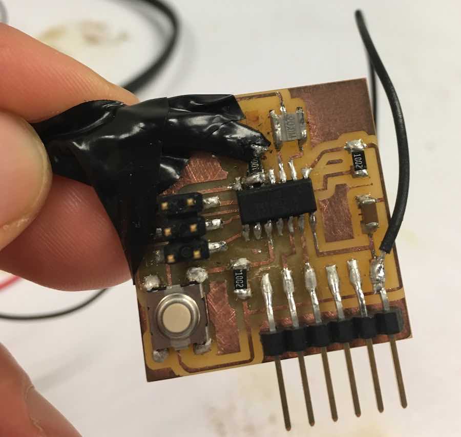
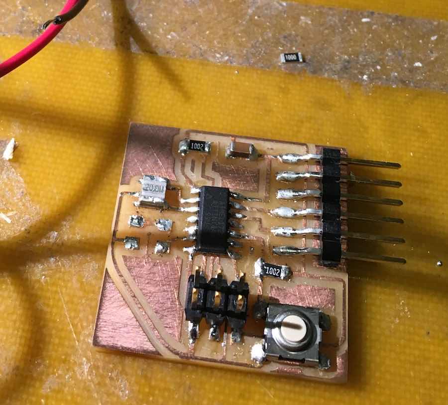
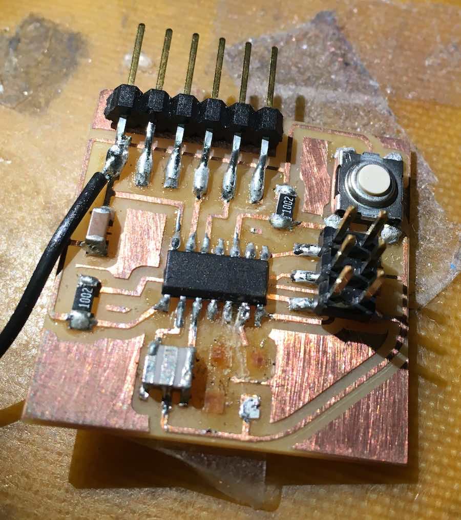
I reattached the power cable and resistor with a bit of solder and lots of electrical tape. Super sketchy, as circuit boards go, but hopefully it'll work as a demonstration... and then I can design a better one with through-holes for the cables and space for temperature and humidity sensors, and maybe even an LCD screen if I have time. The soldering on the rest of this board looks pretty cloudy anyway, so it'll be good to start fresh for Inputs week.
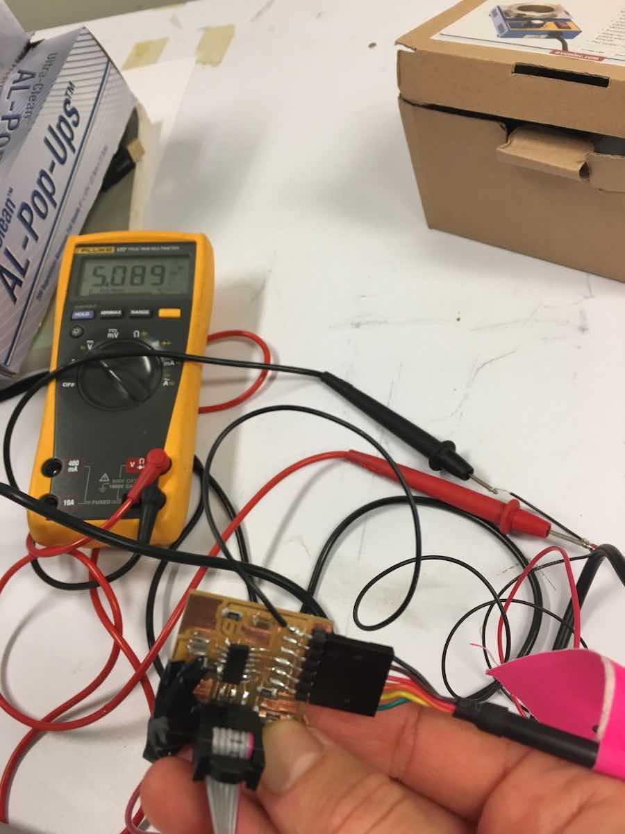
Before wiring up the fan, I thought it prudent to test out this dodgy circuitboard. I loaded up the button-pushing code in the Arduino IDE that I wrote the other week, and then initialized my conjoined pin as an input so it wouldn't interfere with anything. I left the rest of the code the same, so the board should output 5V through the pin with the fan whenever I hold down the button. Testing with a multimeter, it all worked out! (The first time my Mac's USB port acted a bit wonky, but I plugged my board into the other USB port and the simple code ran perfectly.) I then decided to change my code around so the fan came on automatically, and turned off when I held down the button.
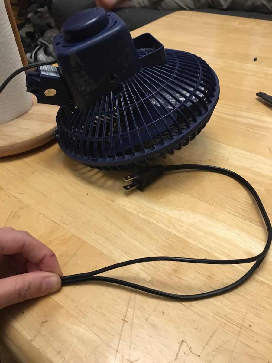
The next step was to split the hot wire on my fan so power can run through the SSR to switch it on and off. I started by carefully cutting apart the insulated wires, which were melted together.
On my fan, I identified the hot wire as distinct from the neutral wire through three features (found on this Family Handyman website, where I got this image: it's attached to the thicker side of the wall plug, it has writing on it, and there are no ridges along the cable like on the neutral wire.
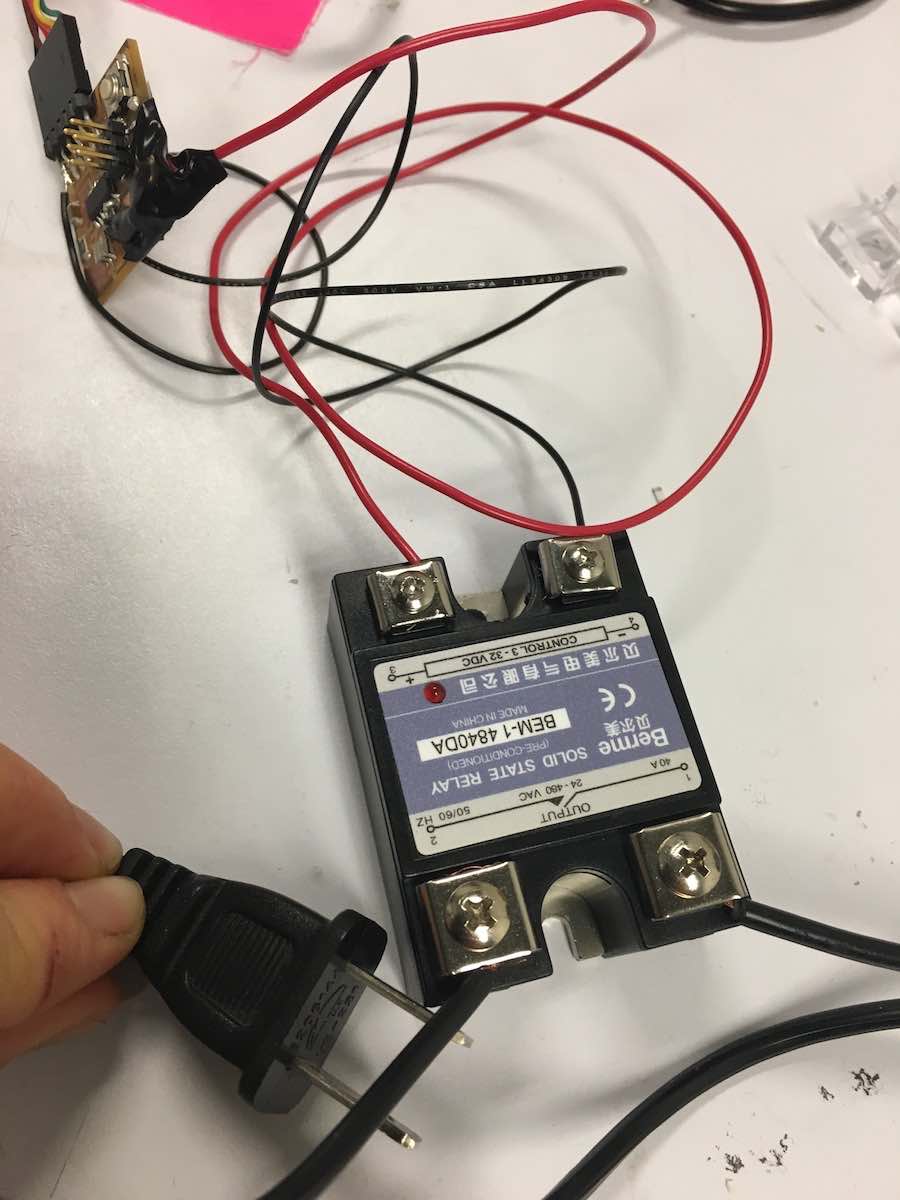
Then I stripped all the wires, and screwed them into their proper spots on the SSR-- making sure that all the exposed cable was under the screws. I then hung around the electronics shop until Will and Prashant showed up for office hours, and I got their approval before plugging the fan into the wall outlet.
I plugged the fan into the wall, and it worked! The fan spun at its default speed but stopped when I pressed the button on my board. No one came close to getting electrocuted. Thus concludes a successful week of simple power electronics. The next step will be to add a pump and sensors and start building my final project...