How To Make (Almost) Anything
Week 12 - Networking and Communications
Introduction
This was a rough week for me. I really tried to get my board to work, but there were too many failure points, I ran out of time and couldn't debug it properly for serial communication. Luckily, my final project is all about asynchronous serial communcation, so I can talk about what I did for that to complete this weeks assignment. If I had to do it over, I'd love to learn more about wireless communication. I am in luck however, because as Neil said after class, the end of the How to Make Almost Anything is truly just the beginning.
Asynchronous vs. I2C
Originally, for my final project, I considered using I2C per the recommendation of my labmate. However, given that my circuits were reasonably spaced from each other and because software serial was such an intuitive tool, I decided to switch my boards to asynchronous communication. The main difference between the two protocols on the design and fabrication side is that I2C requires pull-up resistors on the SDA and SCL lines, while asychronous communication doesn't require pull-up resistors. I2C (inter-integrated circuits) is a synchronous, serial communication protocol which is intended to allow multiple slave digital ICs to communicate with one or more master chips. This type of communication is most appropriate for short distance communications within a single device. Each I2C bus consists of a clock signal and a data signal. The clock signal is generated by a current bus master. For asynchronous communication, you don't really want multiple devices trying to talk at the same time. But for my project, I realized that wouldn't be a problem because there was only one train on the track, so only one node would be trying to communicate at maximum.
TX/RX
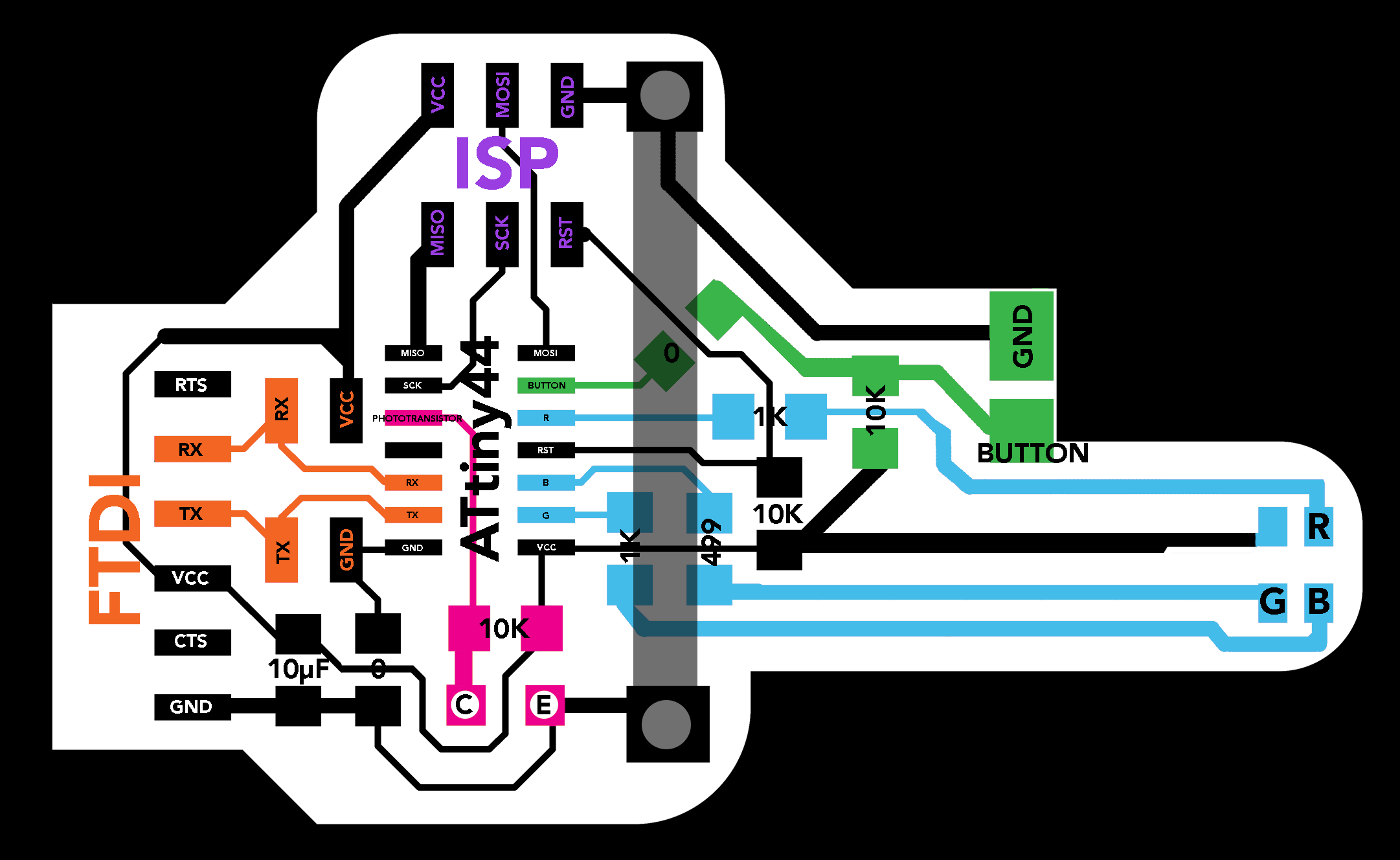
Figure 1: FTDI Board Diagram
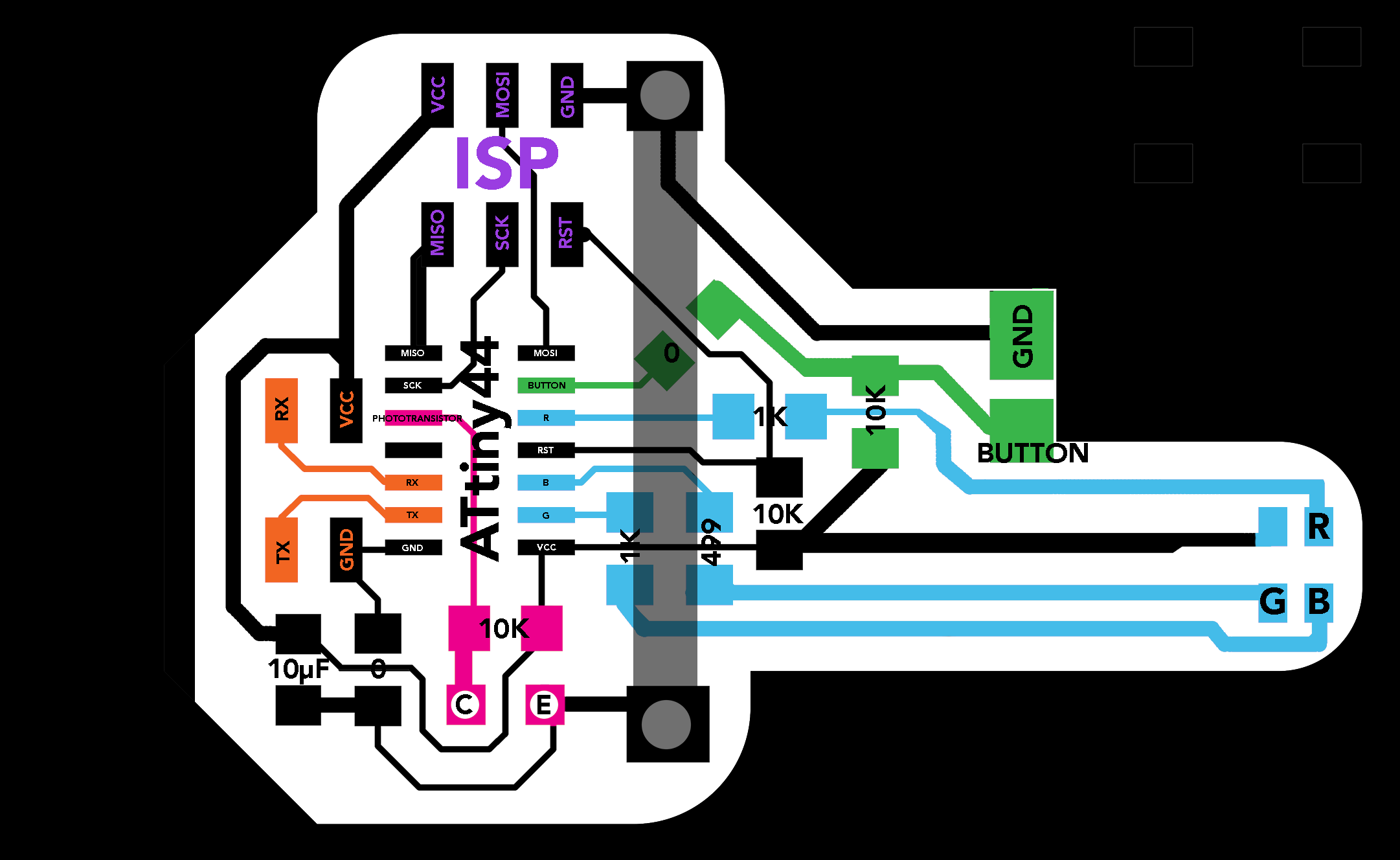
Figure 2: Child Board Diagram
Above, you can see that my ATtiny44s are connected via the TX and RX lines to a 2x2 pin header (and an FTDI header on the board that connects to my computer). Something that was sort of tricky for this project is that TX and RX are flipped relative to the computer in software serial. So, you won't get any communication to or from the board if they aren't swapped appropriately. The 2x2 pin header was used to create pins for me to solder wires to my VCC/GND/TX/RX copper lines on the top of my track. Additionally, in my software, I had to add a line that pulls the TX line high before trying to transmit data. If not, the signal fluctuates while switching the pin to an OUTPUT pin, resulting in trashy data. The Arduino hardware has built-in support for serial communication on pins 0 and 1 (which also goes to the computer via the USB connection). The native serial support happens via a piece of hardware (built into the chip) called a UART (Universal asynchronous receiver-transmitter). Becuase Arduino users wanted to assign more pins for serial communication, the SoftwareSerial library was created. Lucky for me, I could use this for my project as ATtiny44s don't have any built-in hardware communication pins (UART).
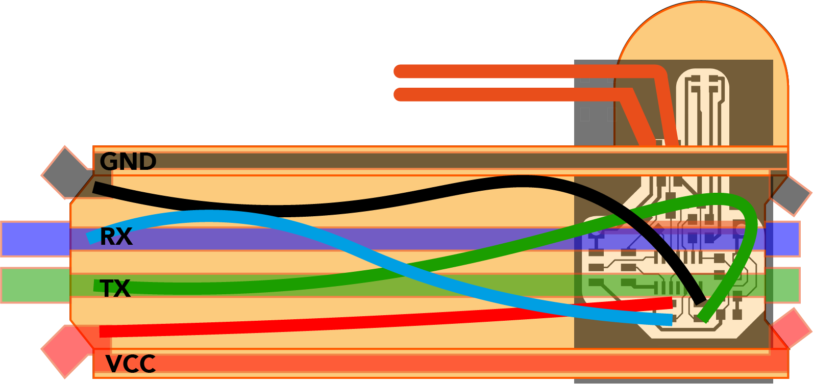
Figure 3: VCC/GND/TX/RX rails on track
I'm really proud of the work I did to learn about serial communication for my final project! I can't wait to continue to learn about serial communication and wireless communication. Additionally, I want to try to figure out better connection strategies for communication lines. Maybe magnetic pogo pin connectors? Or conductive foam?