How To Make (Almost) Anything
Week 6 - Embedded Programming
Introduction
In addition to programming my board from week 4, I wanted to continue to improve my circuit design skills. The first week I used Eagle, the program, the design rules, and the syntax were all so new to me, it was super difficult to do anything except try to complete that week's assignments. I ended up asking Tomas for advice, since he was experienced with the software. He walked me through how to improve my design from last week and I learned many nifty design tricks and rules to help optimize my circuit design.
Eagle Design
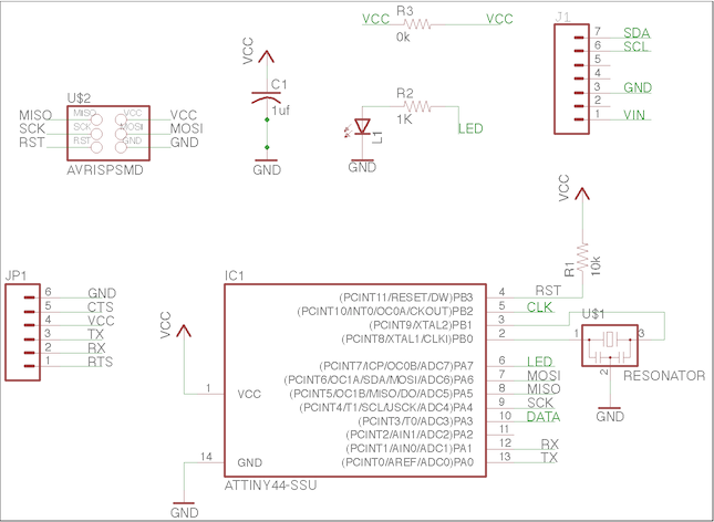
Figure 1: VL6180x ATtiny44 Schematic
Since I had an extra VL6180X Time of Flight sensor, I thought it would be interesting to try to add it to a PCB milled board. Since the sensor already had a 7-pin header on it, I used the sparkfun 1x07 header to create soldering rings. Then in Illustrator, in the outline design, I added holes that overlapped slightly with the copper rings. I was worried that this would take a lot of R&D, but I was pleasantly surprised by how well the pins fit through the milled holes and how seamless it was to solder the sensor to my PCB board.
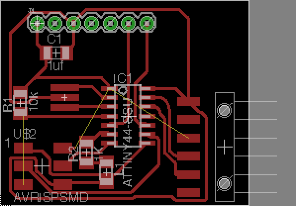
Figure 2: Struggling to connect all the traces (also, my traces were too thick).
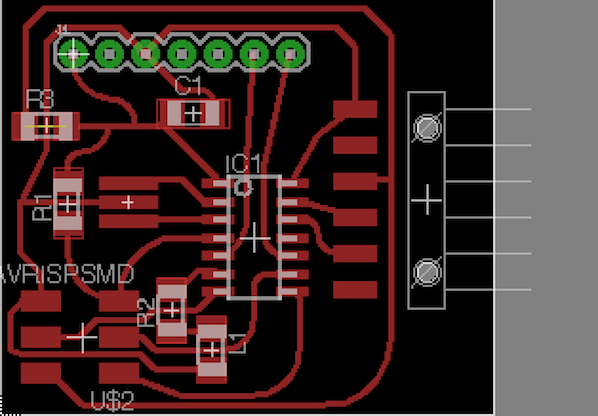
Figure 3: After adding the 0 ohm resistor, much better.
While trying to route all my traces in Eagle, I struggled to find a path that would connect all the VCC traces. I remembered Neil mentioning in class that a 0 ohm resistor could be used to jump over traces, so I added a 0 ohm resistor to my design.
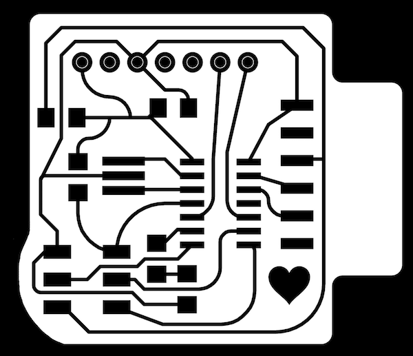
Figure 4: VL6180x ATtiny44 Board Traces and Outline
This time around, my traces were slightly wider and I tried to avoid sharp angles. I learned more about the routing tool and added some fun, curvy designs to my board. I worked on using the surface mounted components to my benefit and placed them in strategic locations that would allow for traces to pass beneath them to complete the circuit.
Board Fabrication
Not only am I getting faster at milling and soldering my FAB boards, I'm getting much cleaner. This week, I had no trouble milling my board. Everything came out clean, and it was straight onto to soldering. After learning that the microscope is my friend, soldering has been a breeze. I can tell when my joints are clean and when the solder is flowing correctly onto the components and the pads. I can't believe I used to solder with just my eyes for reference. Also, double sided tape is now my best friend. It's the elegant solution for holding my board down under the microscope while I solder.
The only concern I ran into this week was how to solder the time of flight sensor to the one sided copper board. I imagine the appropriate solution would be to use solder paste, but since I don't know how to use it and I didn't have access, I decided to risk soldering it while leaving a large portion of the pin exposed. To my suprise and delight, that totally worked. Yes, the time of flight sensor protrudes, but it's a totally solid connection.
Programming
Before programming the VL6180x board, I wanted to start with something a little more straight forward. I revisited my design from Week 4. On the ATtiny44, I had connected a red LED to pin 7 and a button to pin 3. Before adding any functionality to the button, I decided it would be a good idea to get 'blink' to run on my circuit. Because I am familiar with programming in the Arduino IDE and to minimize failure points, I decided I wanted to invest ~$25 and buy an Arduino to use as my programmer.
Setting Up the Arduino
To turn my Arduino Uno into a programmer, I used the following tutorial and some guidance from Vik Parthiban. I found this documentation to be fairly straight-forward, and it helped me better understand my microcontroller. Additionally, it taught me why datasheets are imporant (we'll get to that later). The tutorial was divided into the following steps: configuring the arduino as an ISP, adding ATtiny support to the arduino IDE, connecting the ATtiny to the arduino, uploading program to the ATtiny, and testing with 'blink'.
To configure the Arduino Uno as an ISP, first I connected my arduino my macbook and opened the arduino IDE. Arduino coveniently comes with an example file called 'ArduinoISP'. I uploaded that file to my arduino. Next, I downloaded and installed an ATtiny board manager repository as the arduino library doesn't support ATtiny by default. In the IDE, under the tools menu, I selected the board as 'ATtiny24/44/84', the processor as 'ATtiny44', and the clock as 'Internal 8MHz'. I selected the port as 'Arduino Uno' and made sure the programmer was set to 'Arduino as ISP'.
- 5V - VCC
- GND - GND
- Pin 10 - Reset
- Pin 11 - MOSI
- Pin 12 - MISO
- Pin 13 - SCK
Next, I used male to female wires to connect the arduino pins to the ISP header on my fabricated PCB board. I taped the wires together so it'd be easy to reconnect them to ISP headers in the future. I used the diagram above to help figure out which pins on the ISP header corresponded to Reset, Mosi, Miso, and SCK. Since the tutorial I used was specific to the ATtiny45/85, some translations had to happen. For example, on an ATtiny45/85, pin 0 corresponds to MOSI, but on an ATTiny44/84, it's pin 6. Additionally, I added a capacitor between the GND pin and the reset pin on the arduino to prevent the arduino from being programmed instead of programming the other board. After that, I burned the bootloader onto the ATtiny44, so it would run at 8MHz instead of the default 1MHz.
Blink and Button
Next, I opened up the 'blink' example file in the arduino IDE. I changed the pin from 13 to 7, as that was the pin that my LED was soldered to. I flashed blink to the ATtiny44. It was extremely satisfying to see the red LED on my board light up on and off.