How To Make (Almost) Anything
Week 8 - Output Devices
Introduction
We've reached a point in the semester where I'm starting to feel astoundingly comfortable aquiring and applying new skills. Since that is the case, I decided it was time to start building components that can be integrated into my final project. The assignment for this week was to add an output device to a microcontroller board and to program it. Because I'm working on both a train that makes sound and tracks that display their current state, I thought it would be practical to design a board where you could change the color of a RGB LED and play sounds through a speaker. Initially, I started with a board with one button on it, but decided that it would be more accessible to toggle through colors and sounds than to have to cycle through every option in a linear direction. There were plenty of lessons learned this week, which I detail in the sections below.
Design
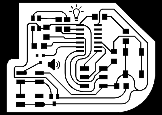
Figure 1: I forgot to finish connecting the traces on this board
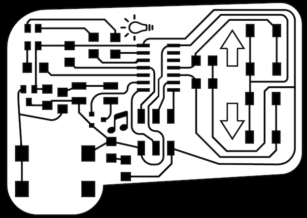
Figure 2: My updated board
For my first board, I designed it, milled it, and soldered on components before realizing that I had forgotten to connect the S pin on the MOSFET to power. Whoops. However, all was not lost as I was able to test the RGB LED, button and power sections of the board. I moved on to my second board, where I decided an extra button would make it easier to toggle between colors and sounds. This time, I dutiously verified that I had indeed routed all my components before milling and soldering my board.
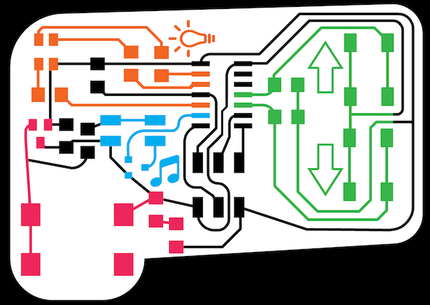
Figure 3: I considered my board as four distinct systems
I divided my board into distinct sections and tried to keep my components close together based on their section. Those sections were power (pink), sound (blue), RGB LED (orange), and input buttons (green). The power section included a 2.1mm Barrel Jack, a 5V .1amp regulator and a blue LED to verify power is on. The sound section included a N-MOSFET and a 2x2 header for connecting the speaker to my board. The RGB LED section included the LED as well as three resistors (for red, green and blue). Lastly, the button section included the two buttons as well as a resistor for each button.
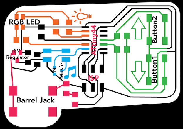
Figure 4: Components Labelled on my Board
I had to add a 0 ohm resistor to jump one of the traces. Additionally, I learned that the labelled Pin 1 pad on the 2.1mm Barrel Jack was actually the ground pin on our particular connector, not the one labelled ground. In future designs, I will run traces directly from that pin, but for this assignment, I corrected the board manually after milling. I continued to practice manually routing my board, and I'm greatly enjoying the puzzle solving aspect of designing PCBs. Additionally, I added icons to my board (the lightbulb, music notes, and arrows) as a form of wayfinding.
Fabrication
I continue to surprise myself, as every week, it becomes incrementally faster and more intuitive to mill my boards and solder on components. I milled and soldered the board above in 30ish minutes. Of course, that board's speaker didn't work because I didn't add the trace to the 'S' pin, but there was some additional learning from that board. I realized that I would rather use a barrel jack to supply power (for convenience). Additionally, I learned that because my ISP header was on the output side of the 5V regulator, I shouldn't use the header to supply power to my board while programming. Instead, I provide power from my external power supply and use the rest of the pins on my ISP header to program my board. When picking MOSFETs, the first time around, I accidentally selected a P-MOSFET, while I intended to use an N-MOSFET. This wasn't particularly disasterous as I could change my programming strategy, however, since I was making a new board anyway, I decided to just swap the hardware for the correct MOSFET.
Programming
I programmed the board using the arduino IDE and my personal arduino uno as the ISP programmer. I modified the sample blink code to work with my boards. For the input on the first board, I had one button on Pin 3 and on the second board, since I added a second button, I added an input on Pin 2. For the outputs on both boards, my R, G, and B output pins corresponded to pins 8, 9, and 10 while the speaker output was pin 7. I defined each of these values at the top of my code as constant integers. In setup(), I defined the pins as inputs or outputs. In loop(), I used a debounce function to make sure that the LEDs would only change color when pressed. For now, I just have the buttons working as separate inputs, toggling through basic color values, but as a next step, I would like to add pulse width modulation to increase the variance of the colors. Additionally, programming the speaker took much more debugging time than expected. Using the oscilliscope, I realized that my N-MOSFET was not working correctly. The speaker pin on my microcontroller was outputting the correct values, however, those values were not reaching the speaker as the output pin on my N-MOSFET was not working properly. I plan on using speakers in my final project, so this will have to be addressed in the coming weeks.