Final Project
After brainstorming through several ideas through the semester, I got interested in making 3D interactive maps for my final project. The idea is to create a map of a city, with building models, that suggest movement of people across the city of Manhattan.
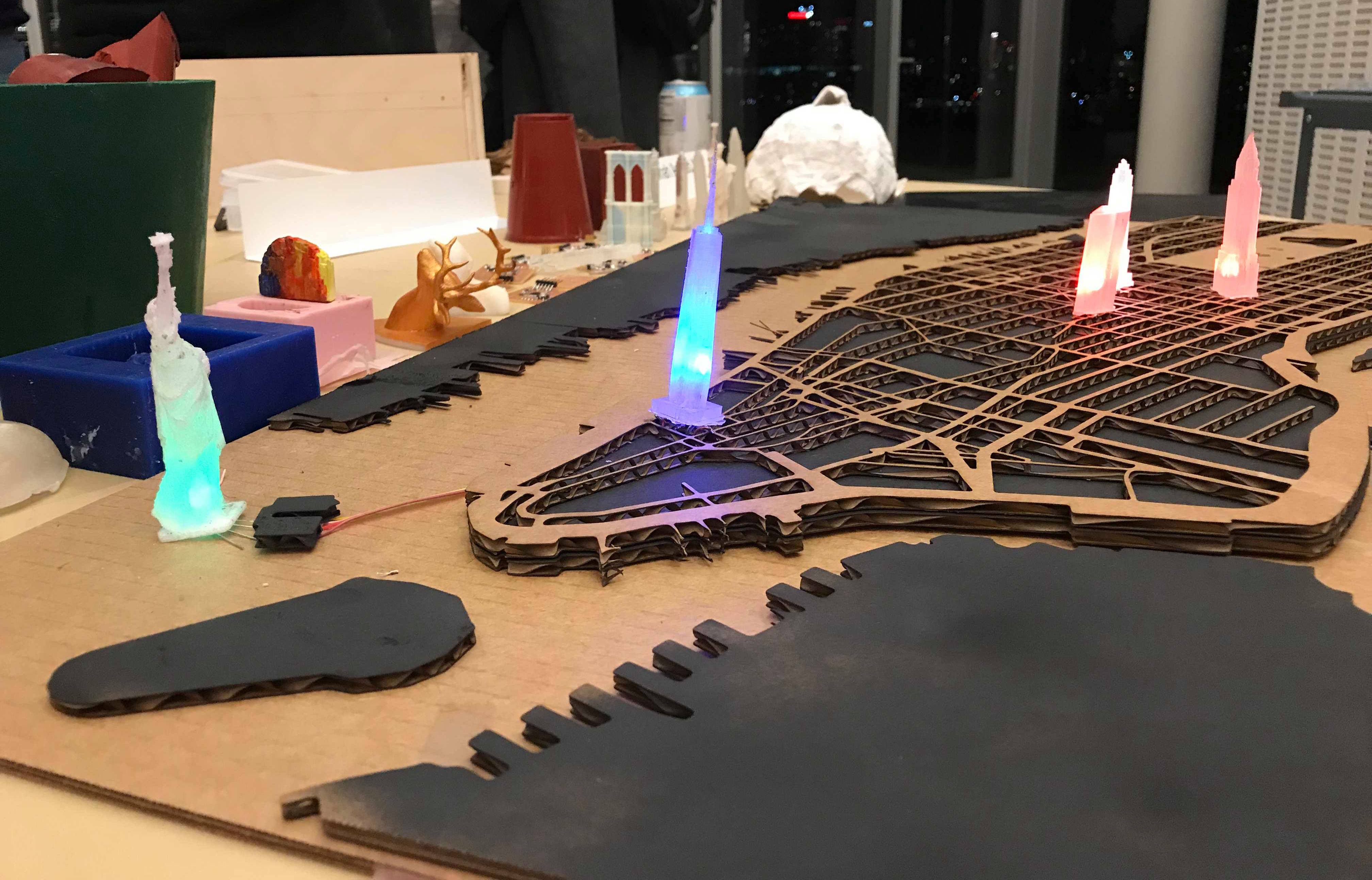
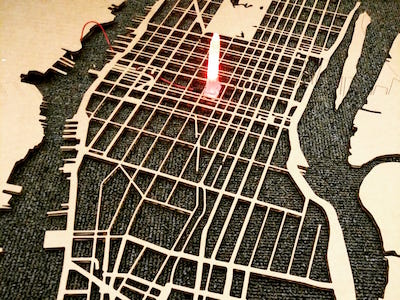
I made a 3d map of manhattan with 6 building models that can light up. The buildings light up when you place them in their correct position on the map, so the buildings can be interacted with. The colors of the buildings, and their blinking frequency correspond to the number of traffic incidents in the building area, and the number of instagram posts with the building hashtag, respectively.
Several data visualizers have made digital interactive maps that depict locations, buildings, traffic. Google maps, Waymo, and Apple maps depict live traffic very efficient, but also only digitally. Computational art groups, example Processing artists, have done a visualization of instagram posts in areas. I wanted to recreate these on a physical map with physical buildings.
Little parts of supplies used
Machines used
All.
I started off wanting to create the world map, but then the scale of the buildings would have been very odd, and I would have had to make really tiny building for it to be realistic, so I decided to do a city. I chose to create the map of Manhattan, because the buildings in the city are most recognizable, and for my love for New York. I decided that I would make reusable molds of the buildings so that I can cast them in transparent silicon with electronics inside. I decided to use the Instagram API and frequency of hashtags to be able to tell people's movement (especially tourists) across the city.
Surprisingly, making the vector map of Manhattan was one of the longer struggles of this project. There are no open spurce vector maps available (But I created one, and linked in below in the resources). I also wanted a particular style of map because I wanted to fit in the buildings, so I wanted the blocks marked off. I also specifically needed a vector format to be able to laser cut it.
I began with going to google maps are marking the area that I wanted. I knew that the minimum building size I could do was 0.7 inch in width to be able to have some detailing (I figured this while 3d modeling the buildings). To that scale, I decided how much of the map I would need, if that maximum map size is 36" * 24" (because that is the size of the laser cutter). Based on that I noted the coordinates that I wanted.

I first tried using Maperitive, and used Monoframework to get it running on Mac. It was not veryhelpful, and I don't recommend it. I found a very helpful software online called QGIS. QGIS helps you make custom maps according to the details you want. It has hundreds of attributes (such as restaurants, buildings, streets, motorways, bridges, water, gardens, etc.). I only used parks, water, borders, motorways, freeways, streets, and bridges. QGIS uses the Open Street Maps plugin (called OSM) to be able to do this. It can be downloaded from the plugin manager. I then made several overlays of each layer and styled them to be able to differentiate what is what.
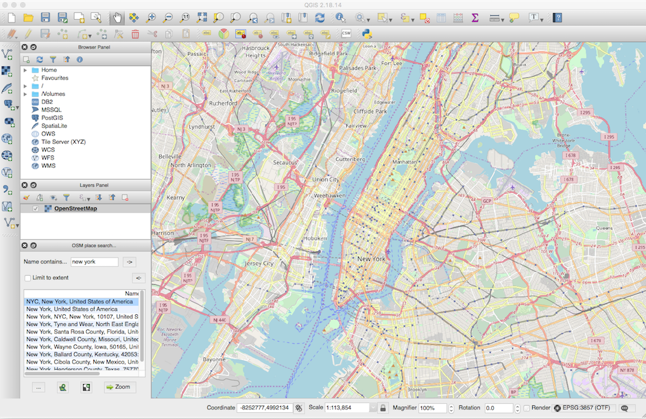
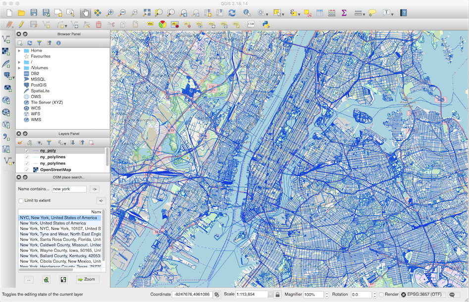
While QGIS was very helpful, it did not have a way to reduce the detailing and stylize parts of an attribute. For example, I wanted to make the motorways thickers to be able to tell the blocks apart. Instead it gives me each street detail with high amount of complex details. I did not want that level of details, and more smooth lines. However, the good thing about QGIS is that it lets you export in vector formats. However, I decided to switch to Mapbox that provides much more support for styling individual attributes of the map. I converted everything to greyscale, and got rid of the details. I made the individual roads thicker, so that their offset merges with the tiny detail streets and they disappear. I also got rid of specific streets that I did not want. I used the water boundaries for the city borders since Manhattan is well suited for that. This is a preview of one of the styles that I generated in Mapbox. You can also duplicate this style if you want a similar style.

One challenge with Mapbox is that they stopped allowing vector format or even high resolution image format exporting. In addition, they also block print page. So, I opened my map on the highest screen resolution I could find, and took a screenshot of the area. I went to Illustrator and did an Image Trace of the screenshot. The image trace led to curvy and complicated anchor points that would not work well with laser cutter. However, Illsutrator Image Trace gives to options to recude complexity, so I did that. Then I expanded to individual anchor points.
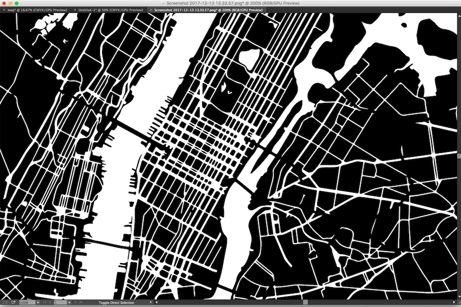
I then used transform options such an round corners, offset paths to make it smoother according to my preferences. I did some trial and error with these options. Then, I used the pen tool and manually tweaked a lot of the paths (especially coastal building paths) to get the effect I wanted. Finally, I verfiied if my buuilding dimensions would fit in the block sizea.
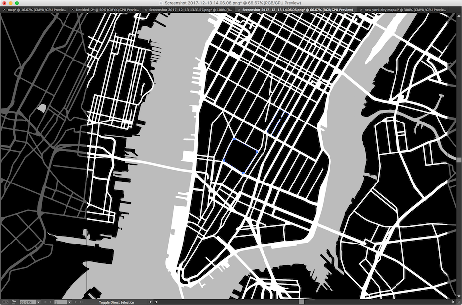
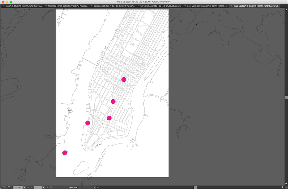
Once I had the vector map ready, it was now time to do a test cut of the map on cardboard. I picked up cardboard scraps in the cba shop to make the first test cut.
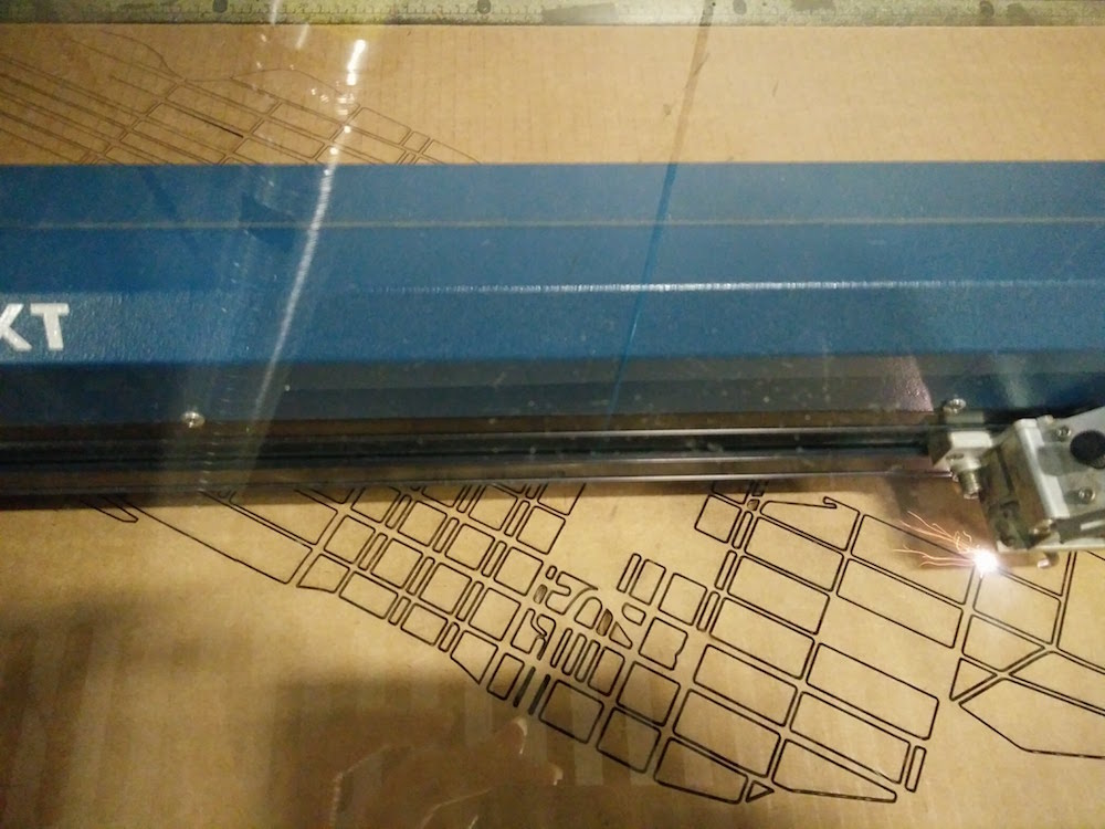
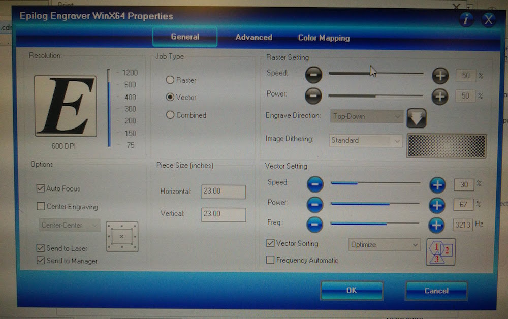
I played around with the printed settings a little to get the right speed and frequency. These settings worked best for cardboard. However, Corel Draw kept crashing for any dimensions above 21" * 21". I spent several hours trying to figure out what was happening. Then I tried printing another 36*24" which was not this map, and it worked fine. So, I realized it was the complex path that was making Corel crash. So I went back to illustrator and manually made parts of the map simpler. Then I cam back to Corel and laser cut the map. The sheet cut out well.
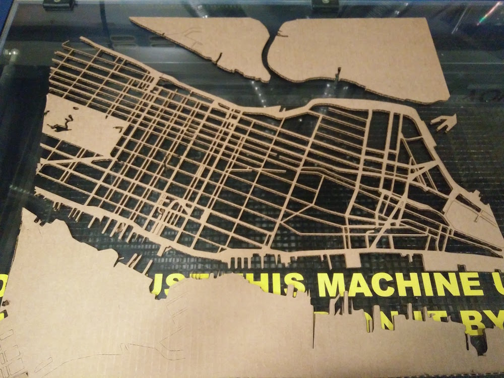
I made this test sheet before using wood, so that I can parallely start making the copper traces and trying to fit them below the map.
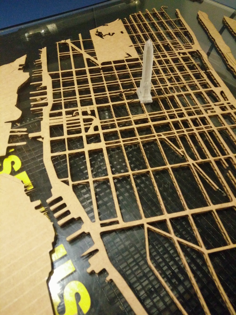
I used my test sheet to place the building model, and wired it to check if it worked in scale, and the scale was fine.
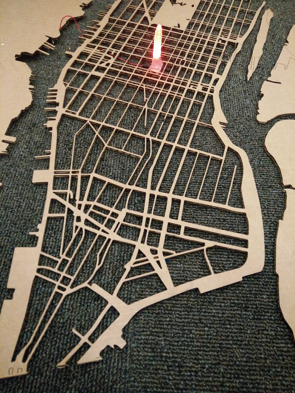
I then began to laser cut in wood. John had some extra sheets of 1/8" plywood sheets that he gave me. I first cut the wood sheet into 2 26*24" sheets.
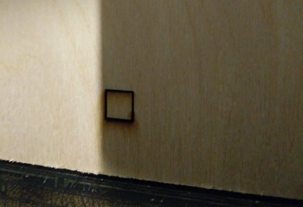
I first did a sample tiny square to get the settings right. These settings work best for the wood.
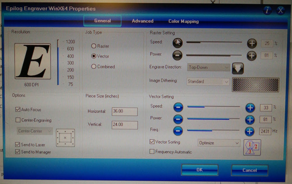
Since the wood sheets weren't completely flat, I used a strong tape to tape it down to the printer edges and then cut the whole map.
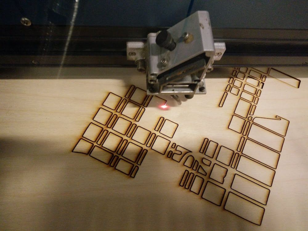
At a first look, it looked really good, however when I removed the sheet and tried to remove the blocks, some of them were stuck inside. This is because the sheets were taped on the side, but still kept lifting in the middle. This was a real problem. Tom advised me not to do this as it could potentially lead to the wood burning.
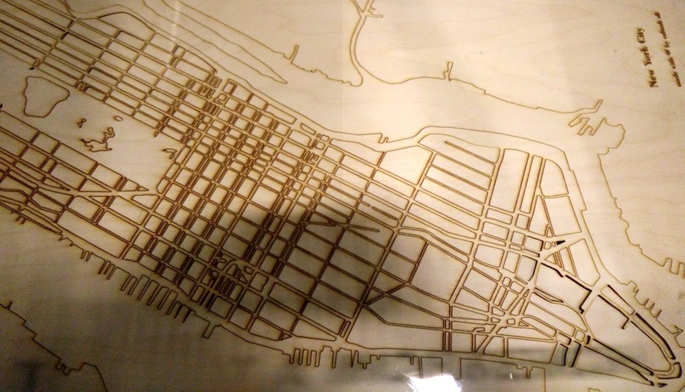
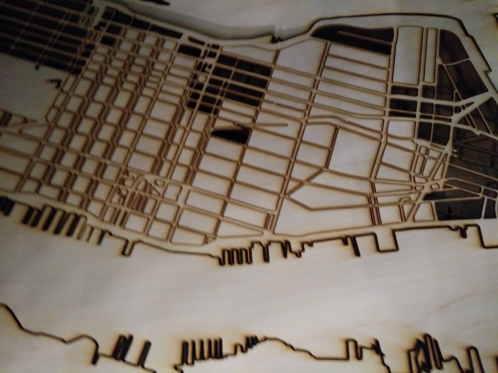
So I looked up online, and saw that people use a wetting and steaming technique for making wood flat. I didn't have the equipment to the elaborate steaming, but I lay the wood sheets out and poured water on it. Then I left them under heavy weights all night.
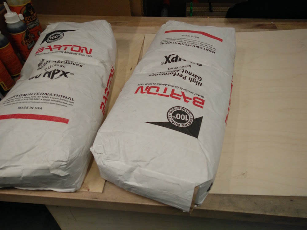
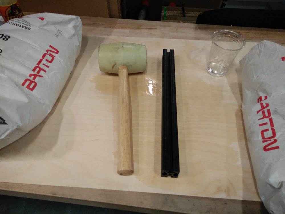
I came in the next morning to discover that it had gotten worse and they were bending more now. It was quite hilarious. Since I had already wasted two full days on this, I decided to go back to good ol' cardboard, and use a base layer of paint to make it pretty.

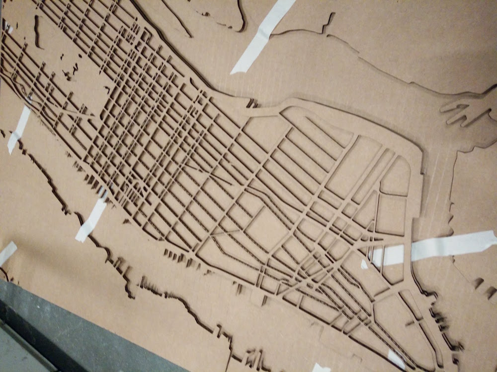
I cut 3 layers of the map in cardboard. One for the city outlines, includinng Brooklyn, Bronx, New Jersey outlines. One for the main Manhattan outline. The last top one for the Manhattan street level details. I did these multiple layers to fit in the wires and traces as you will see below. This was accomplished sing 2 36*24" sheets of cardboard. I then used masking tape to secure them in place.

Modeling the buildings was rather easy for most buildings since tehy are so geometric. You can find 2d structures of most buildings online, and just pull and push them to different widths for every 2d plane. Since the buildings are so small, there is also window for errors, since it is difficult to make out witht he naked eye. So looking at images is helpful. Also looking at digital 3d maps is helpful (and there are plenty for Manhattan). However, for the Statue of Liberty, I found a model on Thingiverse , and changed its mesh in Meshlab to make it simpler and printable in that size (max 0.7" width). I used Google sketchup and Blender to do most of the modeling, and then used Blender to scale them and place them together for one print after the milling failed.
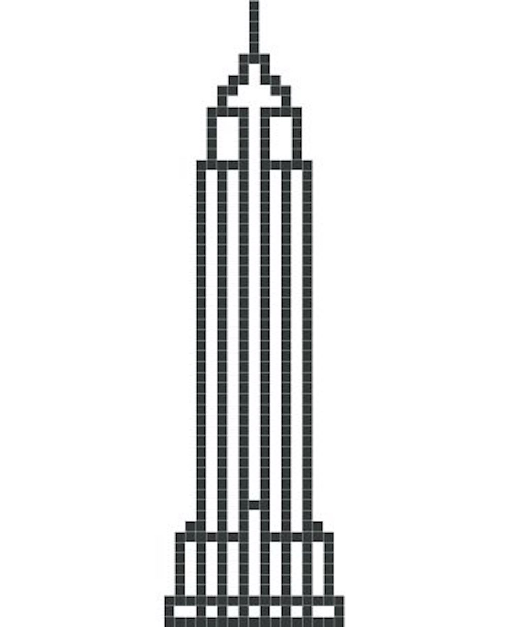
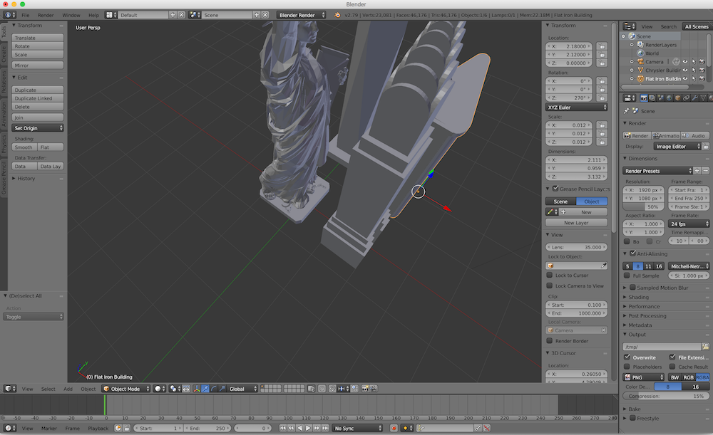
The initial plan was to mill the buildings since they are so symmetrical. So I was silly enough to thing I will mill one side of the building in machinable wax in an approximate 5"*.7".7", and use two part molds. However, milling was a fialure at that size and kevel of detail.

So then I used the 3d printer from the Personal Robots group (Mojo 3d printer) to print these in one print. This printer prints the cupport structures that need to be dissolved with a chemical. This needs another 9-10 extra hours.
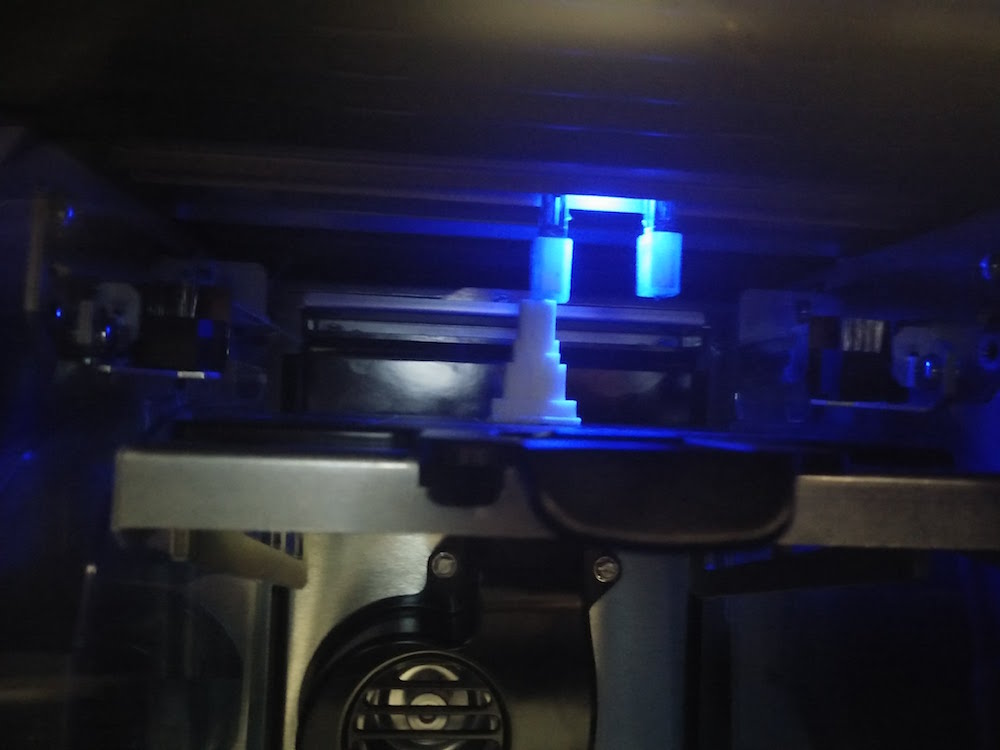
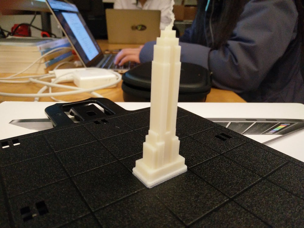
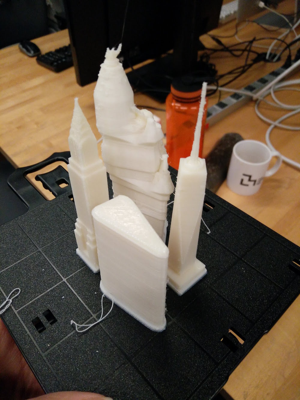
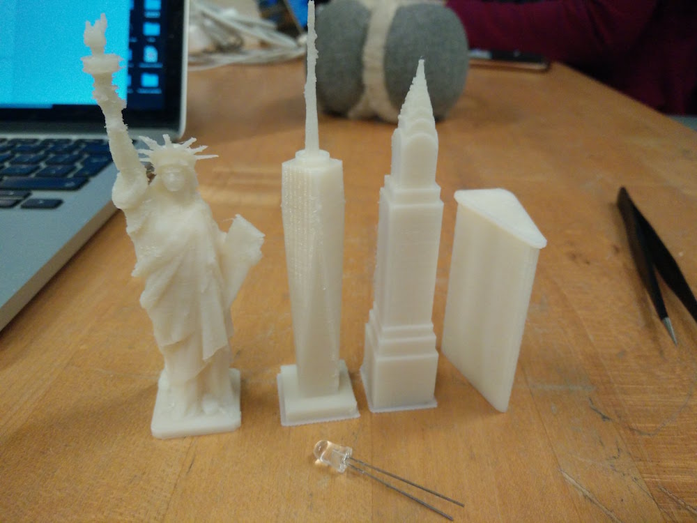
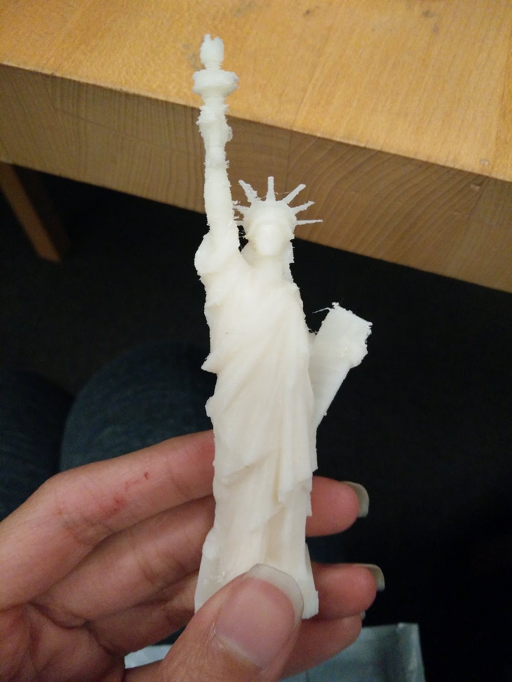
The prints came out surpirisngly well in the first attempt except for the little details such as the empire state needle, or Miss Liberty's hat. So I just glue gunned these back on.
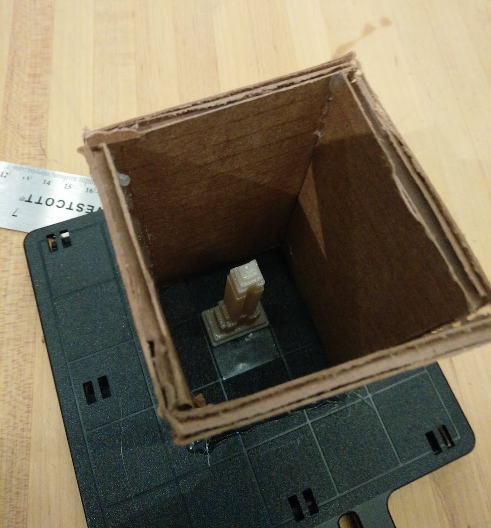
For the molding and casting, I first started with the empire state building, because it looked the strongest and take the fastest to reprint if need be. I made a small box to pour the Oomoo into, and glue gunned the Empire State in it, facing up.
Grace gave me two useful pieces of advice - Use the Mold Max 60, instead of Oomoo, because it is stronger and your models are small, and, poke a hole on the other side of your mold to make sure there is no bubble trapped on the top of the building when you do the casting.
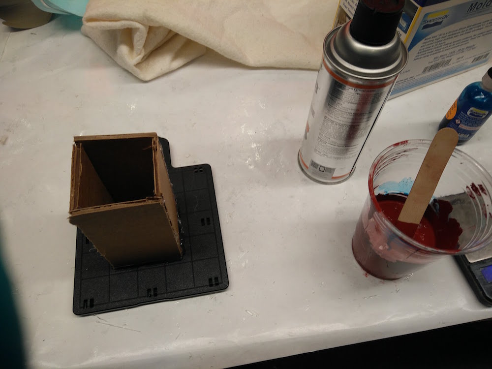
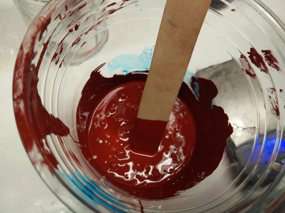
I followed the standard process of mixing, weighing, vacuum chamber, silicon release spray, and tilt pouring to do the moulds.
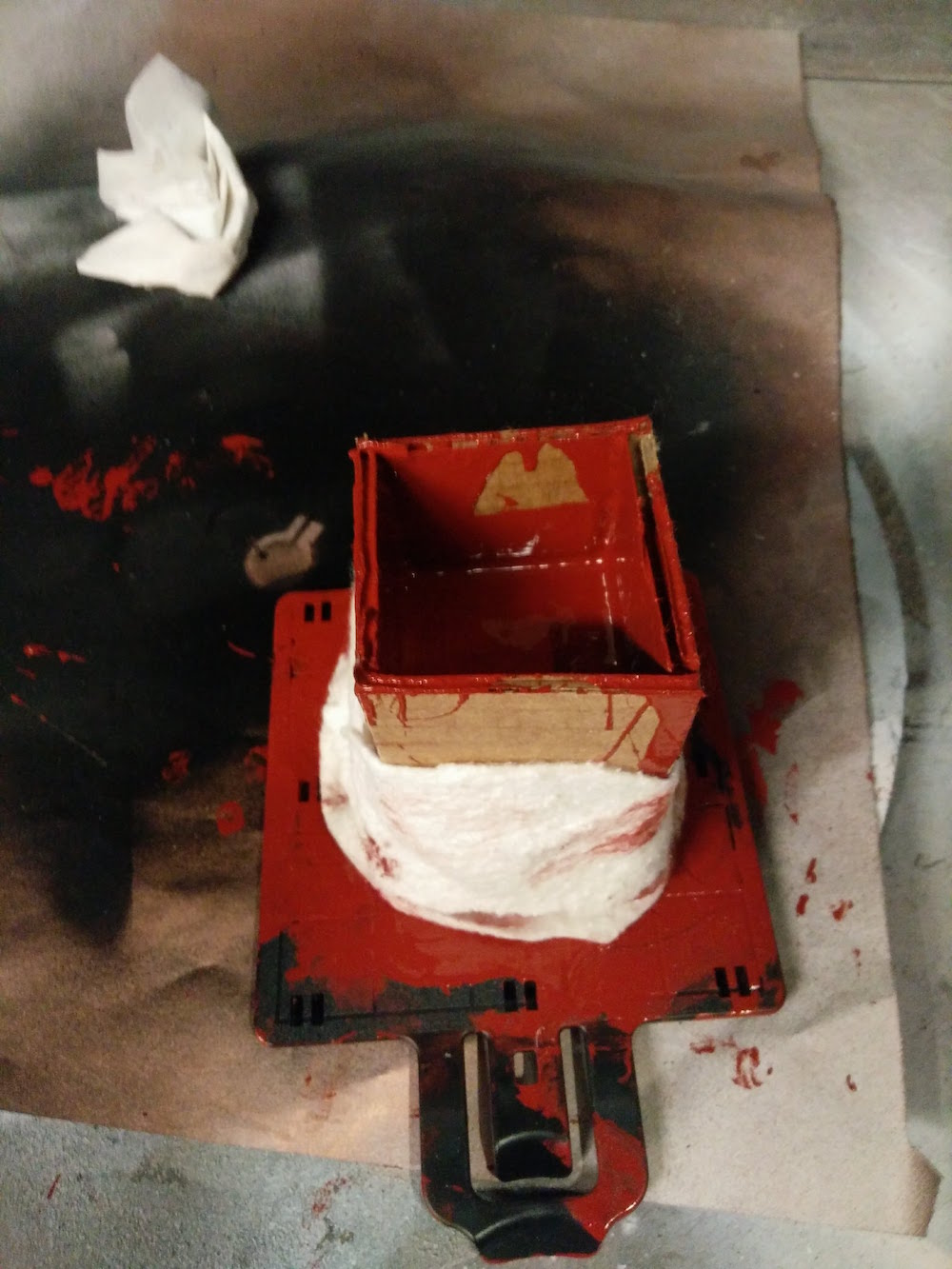
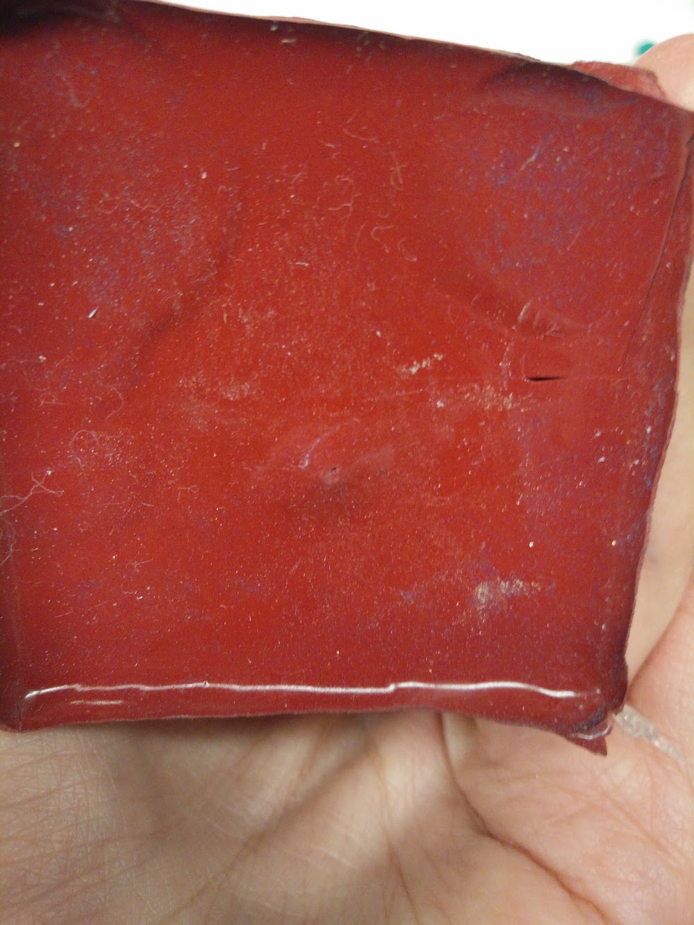
Mold max take 24 hours to solidify. The next day I broke the box apart to realize that the building is stuck inside and cannot be pulled out. So I used a knife to cute out the mould in two parts. A good trick is to cut it unevenly, so it automatically leaves you marks to re-fix the two parts of the molds. Notice the holde poked on the other end of the mold.
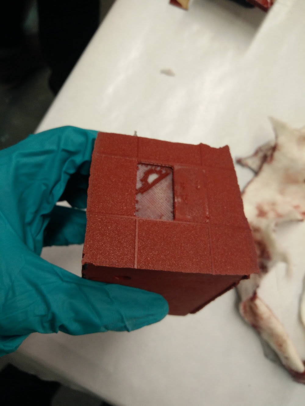
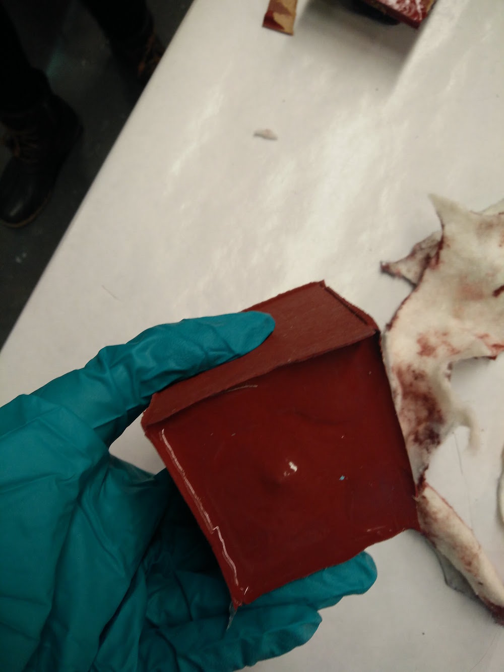
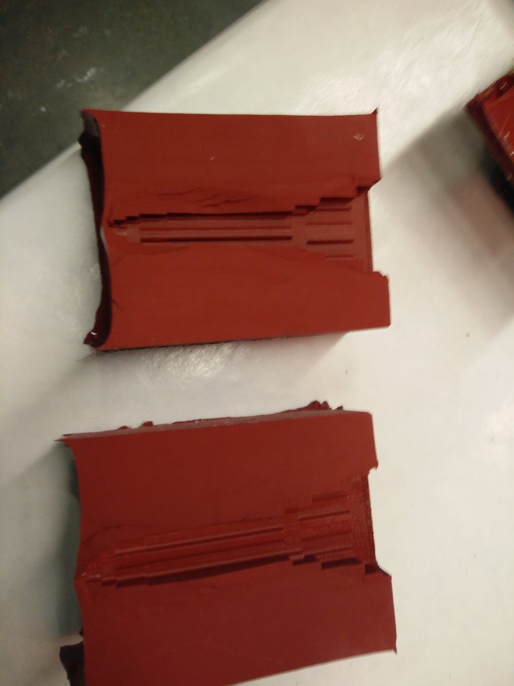

Since the mold looked fine and the building was still alive (except the needle broke again), I went ahead and made molds for all the buildings. Instead of making boxes, I just made their molds in cups I found at the foodcam that were pretty perfectly sized.
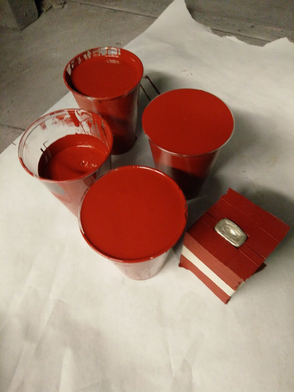
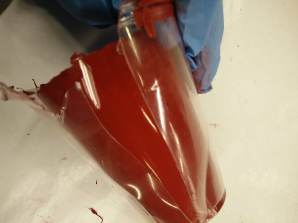
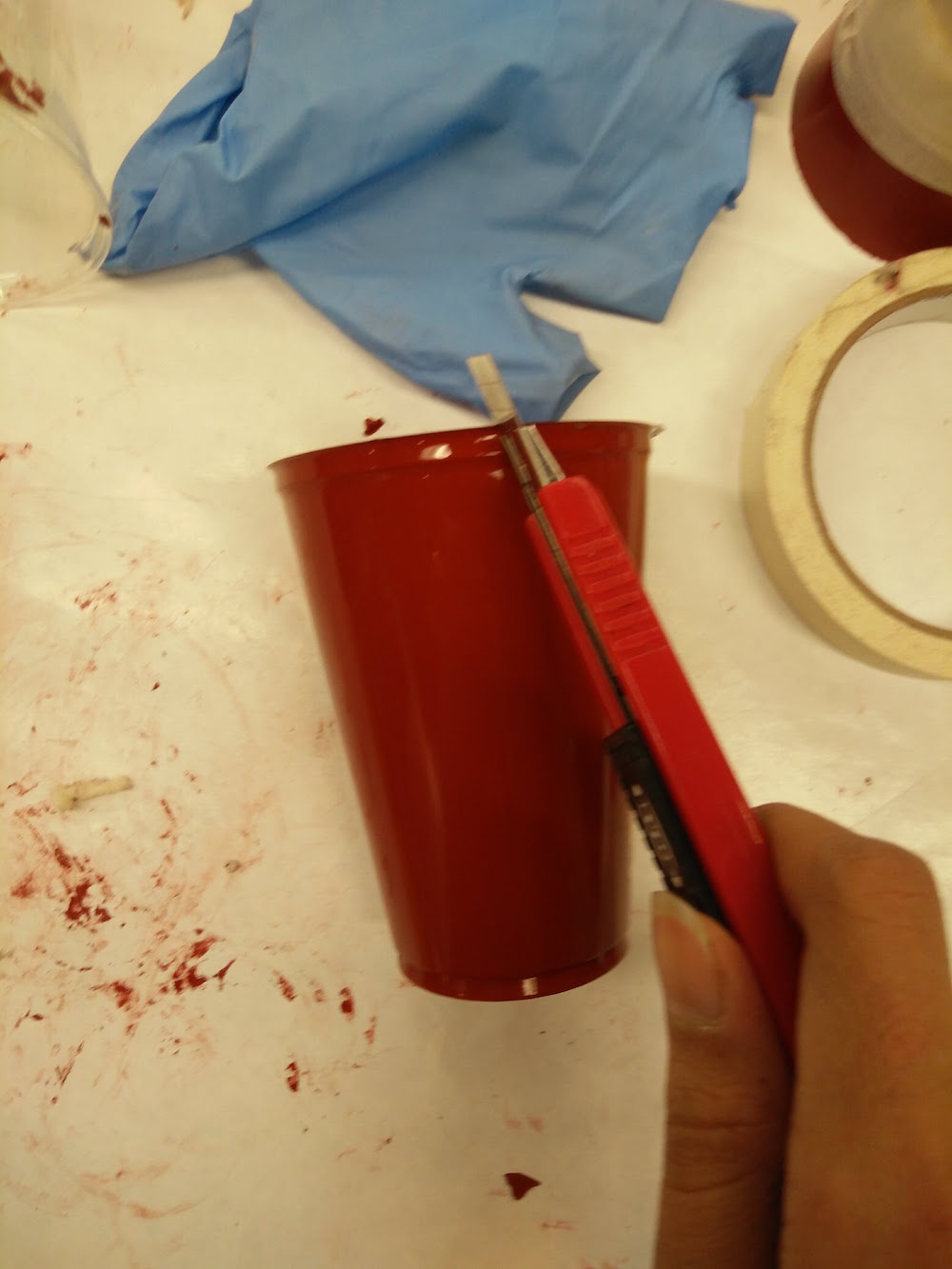
When these were done, I used the same cutting process to make multiple mold parts. For some more complex buildings, there were many parts. Example, the Statue of Liverty was a 9 part mold because of the detaisl in the hat and in her torch. It could have been lesser parts had I pre-planned the parts and where to cut. But it was fun to solve the puzzle of refitting those parts back together.
While the other molds were drying, I casted the Empire State building. I was looking for materials and was first considering Dragon Skin. I found another material called The Smooth-Cast™ 326 ColorMatch™ that is ideally supposed to be used to mix dyes in, and make any color. But I realized if you don't mix a dye in, and mix it in the wrong ratio (do 100:90 instead of 100:115), it leads to sort of transparent/translucent casts, that are perfect to put LEDs inside. It took some playing around with a tiny quantity to figure this out. However, since the ratio is incorrect, it leads to soft models which bend easily, but that gave a nice flexible feel to the buildings, so it worked for me.
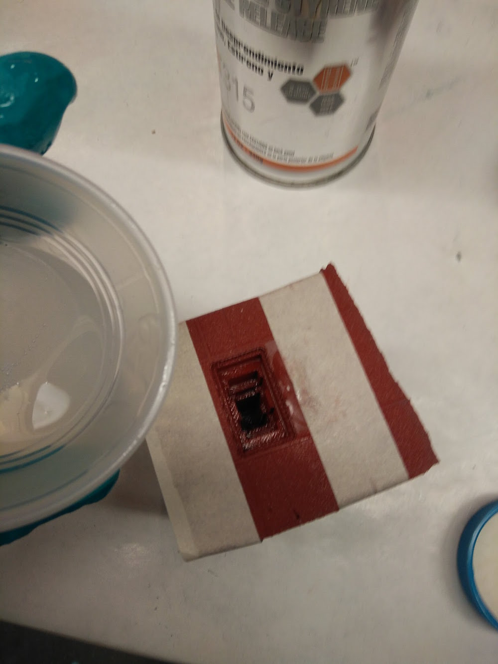
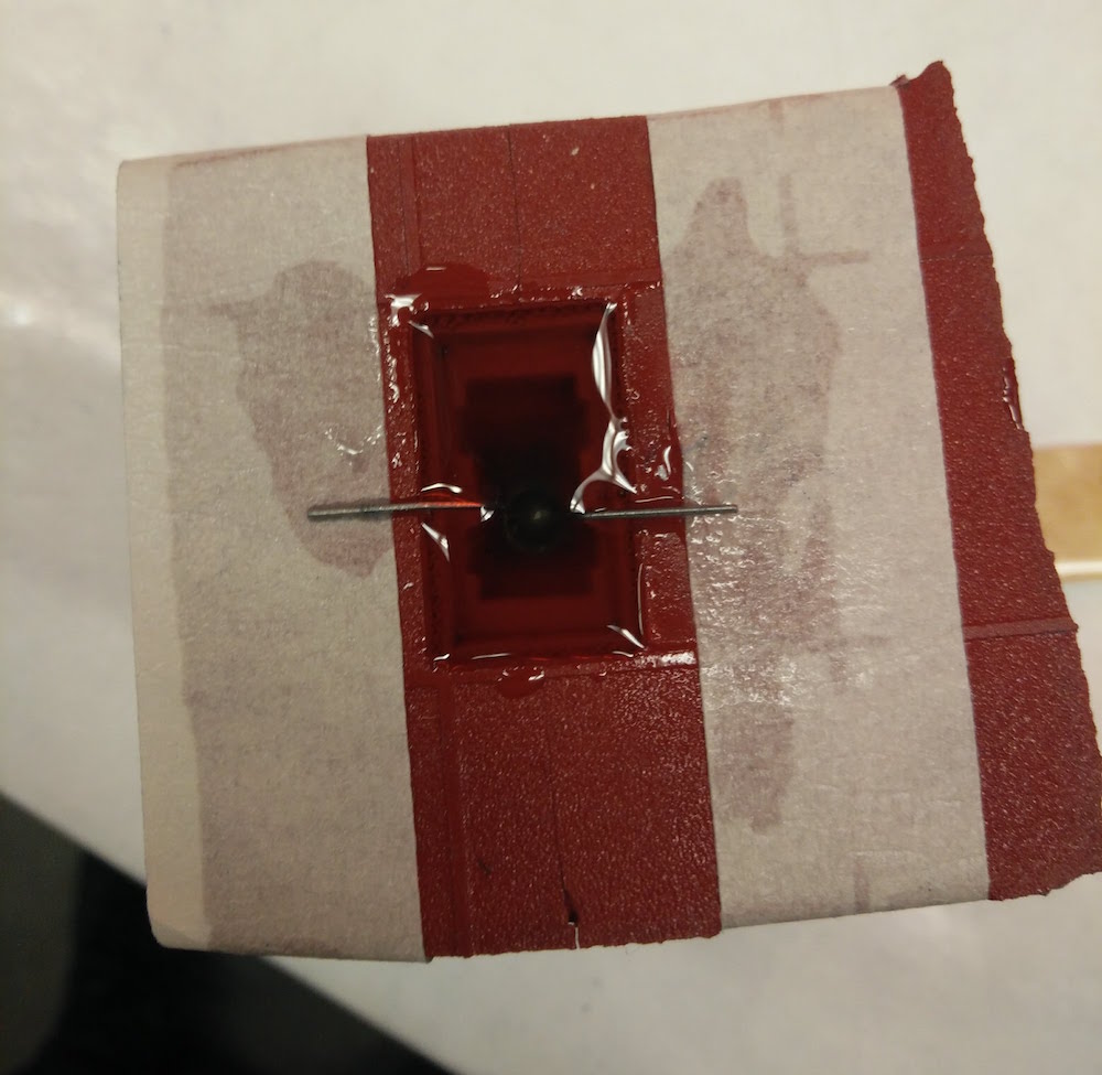
I poured the casting material upto 95% of the mold, and then dipped an LED inside it. I used tapes on both sides to be able to keep the LED anode and cathode legs dry and out of the Smooth Cast stuff. Note that this incorrect ratio also increases your setting time to about 2 hours, adn you can check that if you had any leftover liquid in your cup (save it to check on time). After two hours, I took the casted part out, and it looked pretty good.
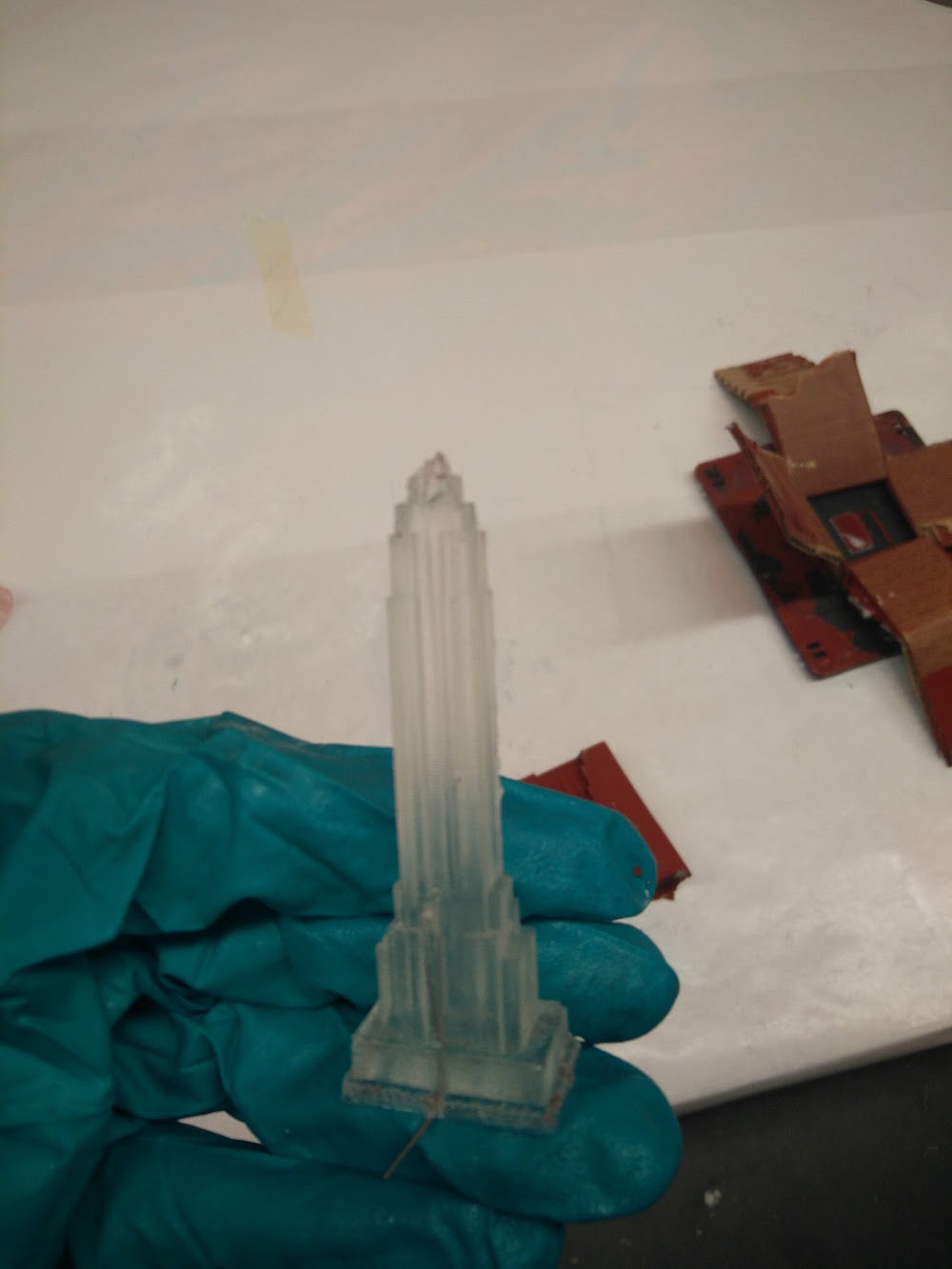
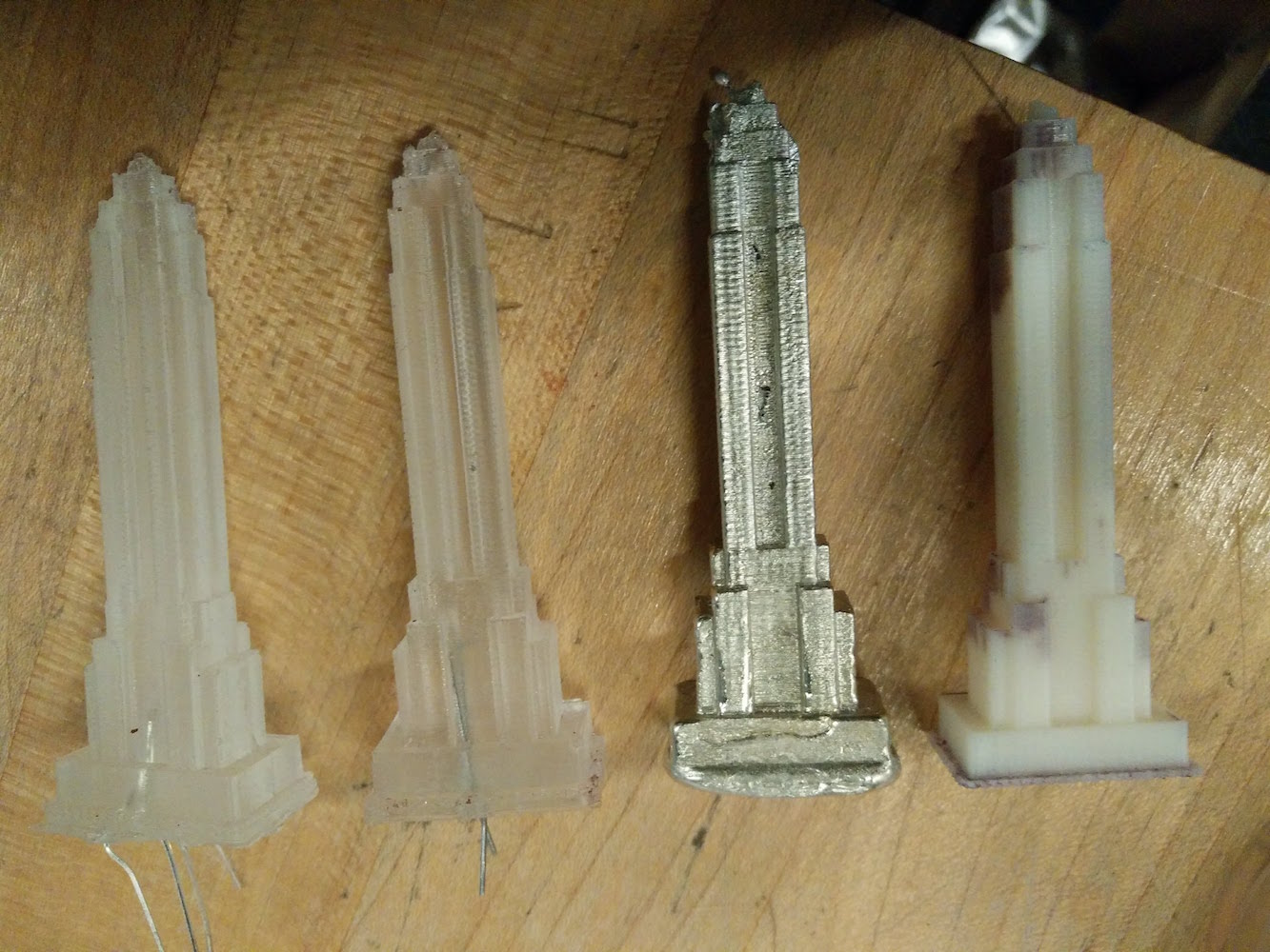
Here you can see the original 3d model and the casted part.
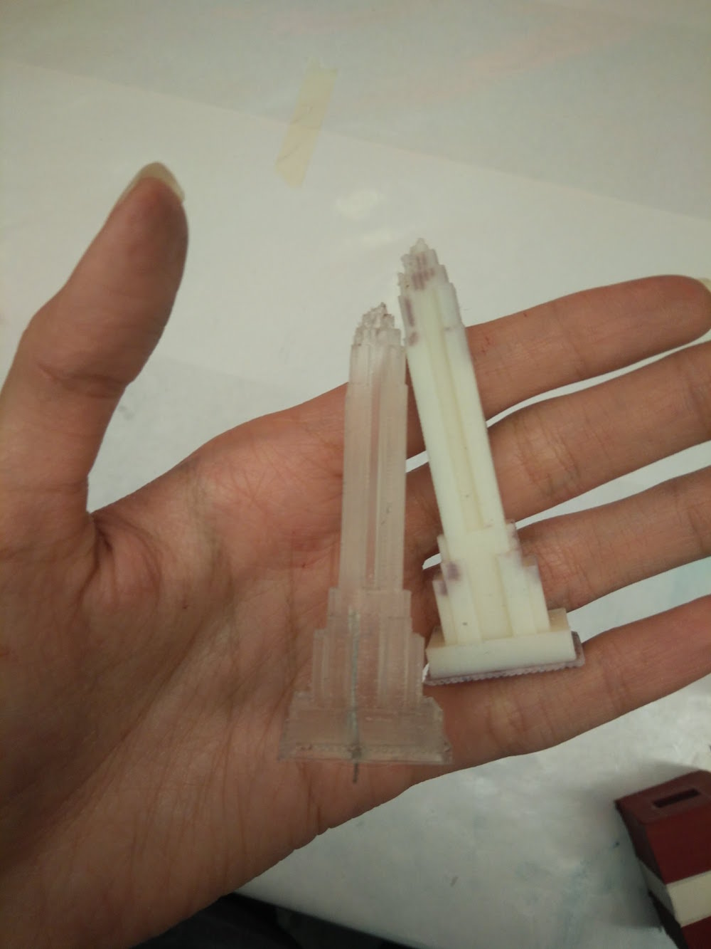
I also did a metal cast for fun.
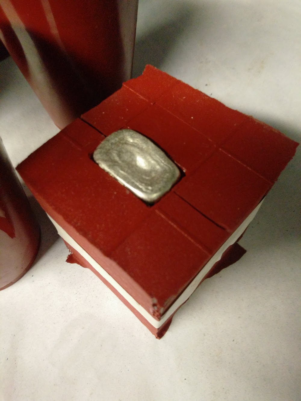
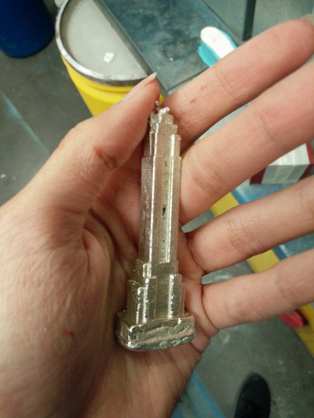
The mold parts had to betaped together very securely and carefully to ensure that there is no leakage in between the molds.
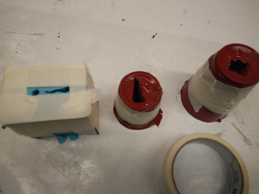
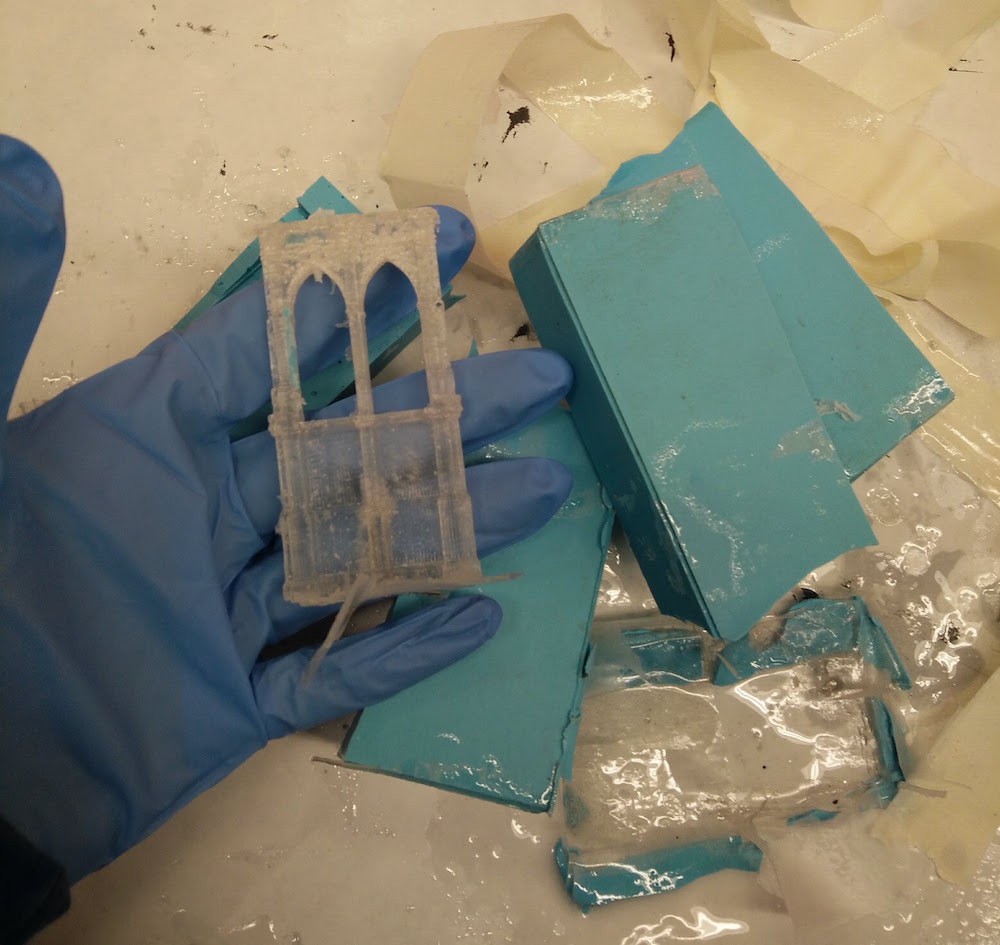
I made an extra Empire State and put a simple red LED inside it (the main one has RGB) to do my testing.
I added a current limiting resistor and tested out the buildings by lighting them up using my Attiny board, and it seemed to work pretty well. I had to work through the values of the RGB ones to get the brightness just right. I also used a delay and brightness scale to get the fade effect, which eads to a light rising up effect inside the mold. More about this in the electronics section.
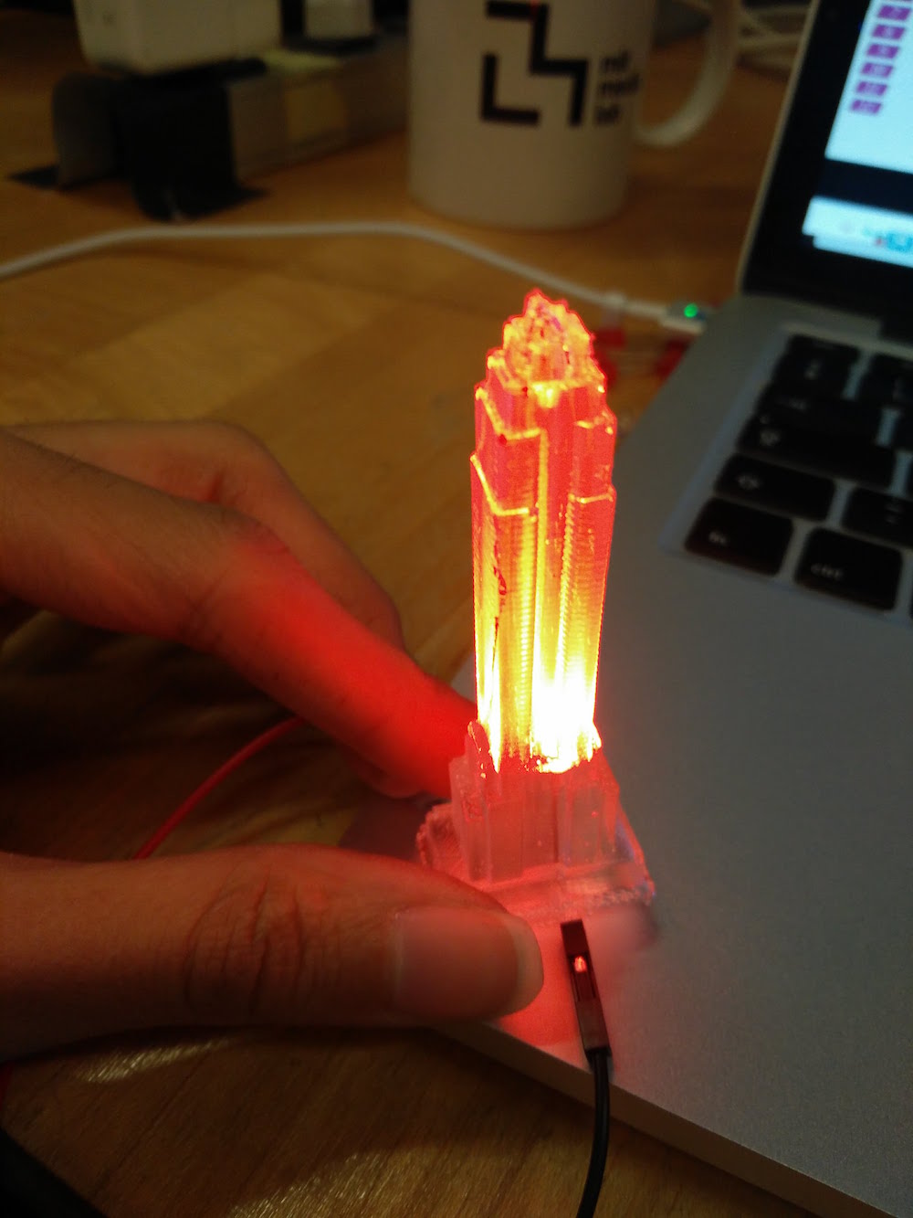
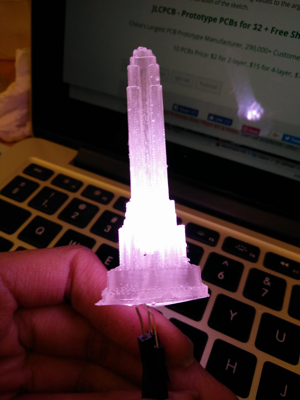
Time to power all the LED's inside the buildings independently!
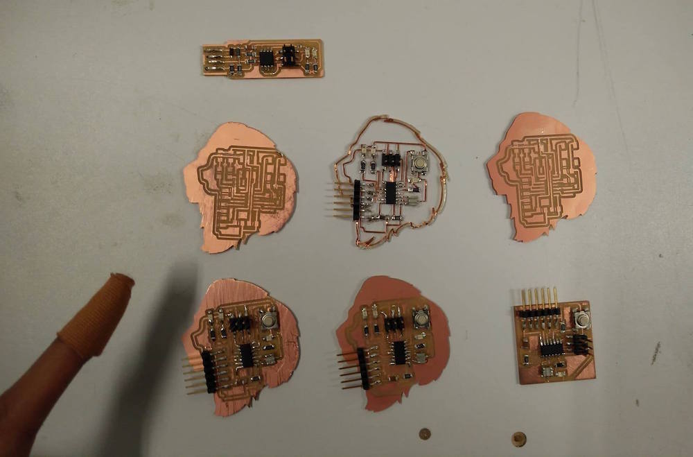
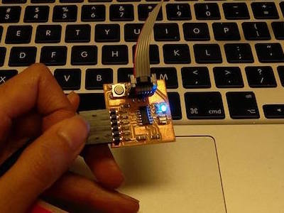
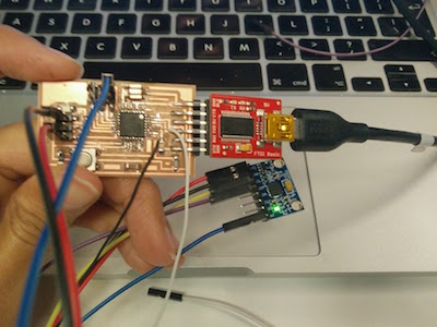
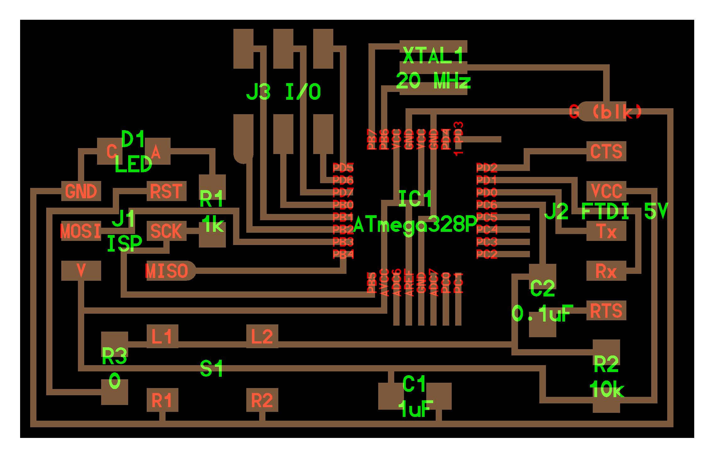
I first started doing individuals with the Attiny44 board I had designed that lights up 3 LEDs sequentially. See the circuit and traces below. This worked for one individual building as seen above, but wasn't enough output pins to do all the lights.
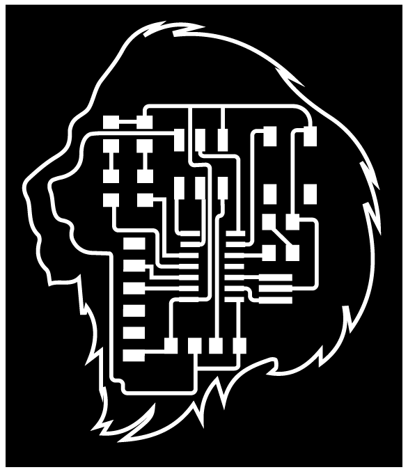
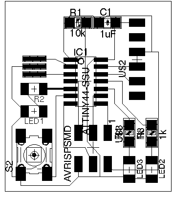
So I decided it was time to make my Fabkit board which is an Arduino clone that uses the Atmega328p. I followed the Fab Academy tutorial to get the schematic files, and created the v0.4 version of the board.
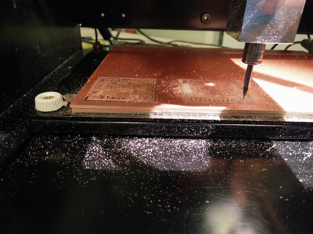
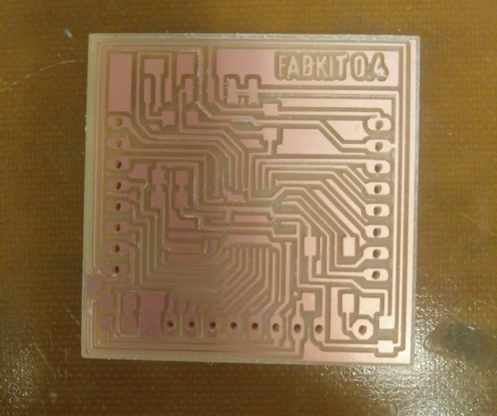
However, when I tried programming it using the USBtiny programmer we had made in the Electronics Production week, the board did not work for me. I kept getting a timing mismatch, and the programmer did not respond while burning bootloader. I double checked the circuit, reflowed everything, used someone else's programmer, but nothing worked.
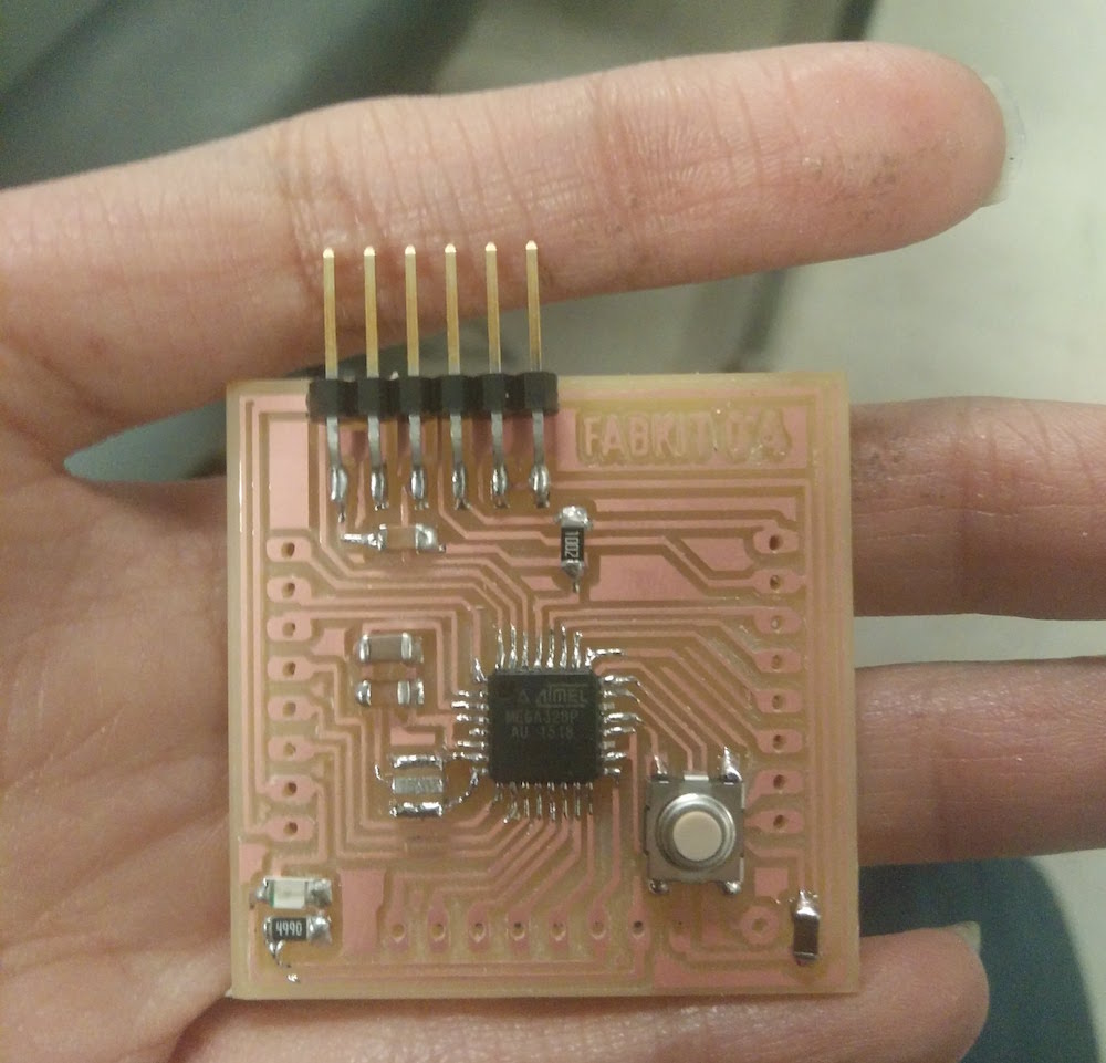
So I made another board.
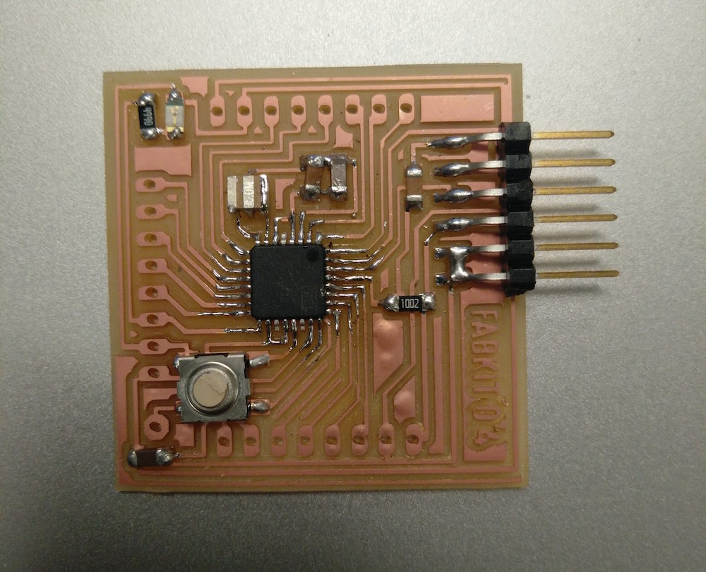
And another board.
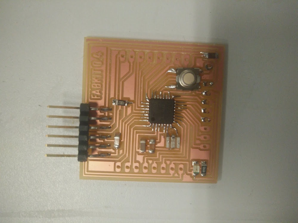
Then I made some changed to the design according to where I wanted my output pins, used an Atmega168u and changed the resonator again. This board actually successfully burnt bootloader, but still would not upload code.

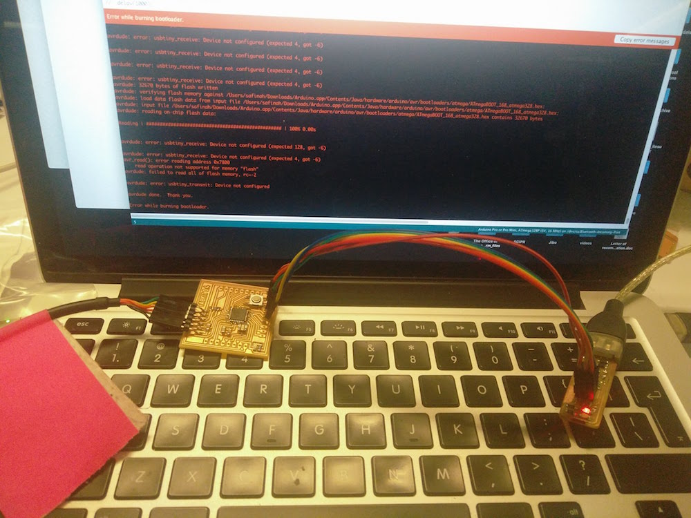
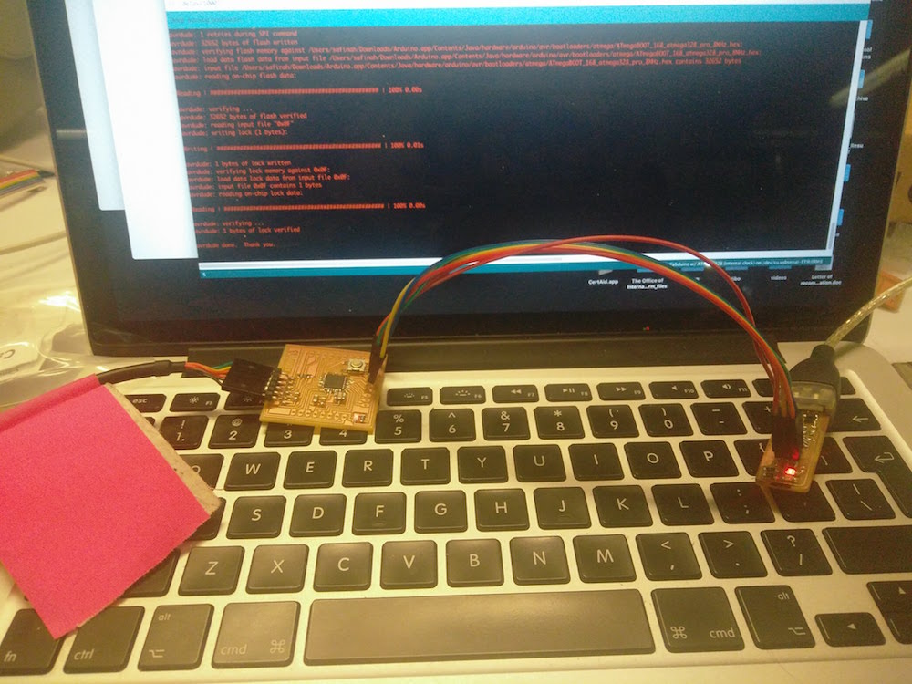
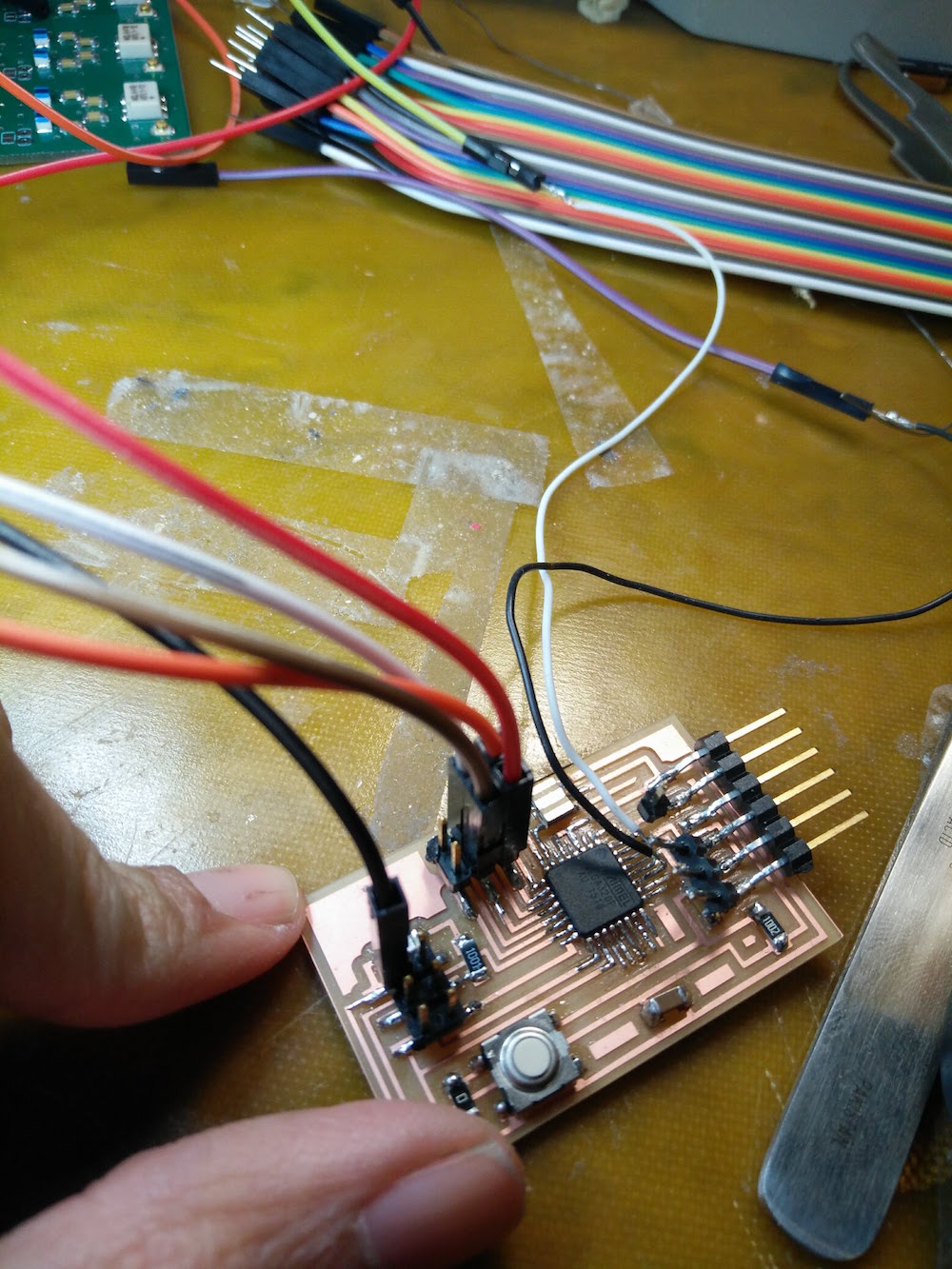
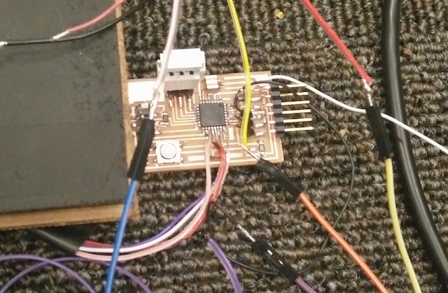
Since I had already spent one full day and night on this, I went back to the board I made for output devices week (which is based off off the hellow arduino board by Neil), and made a slightly different output pin arrangement. I also soldered extra wires directly onto the board to be able to use the other output pins I had initially not used.

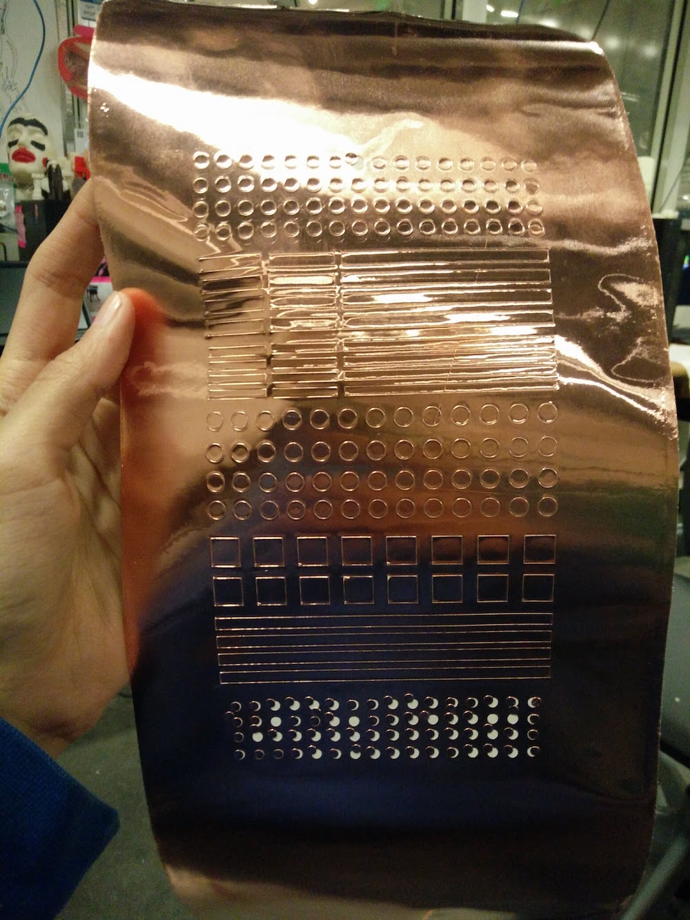
I also made a vinyl cut sticker sheet that I could use on the cardboard cutout maps. I made these to scale to the buildings and the maps.
I used the map detail top layer cutout to draw the block shaped on the second layer.
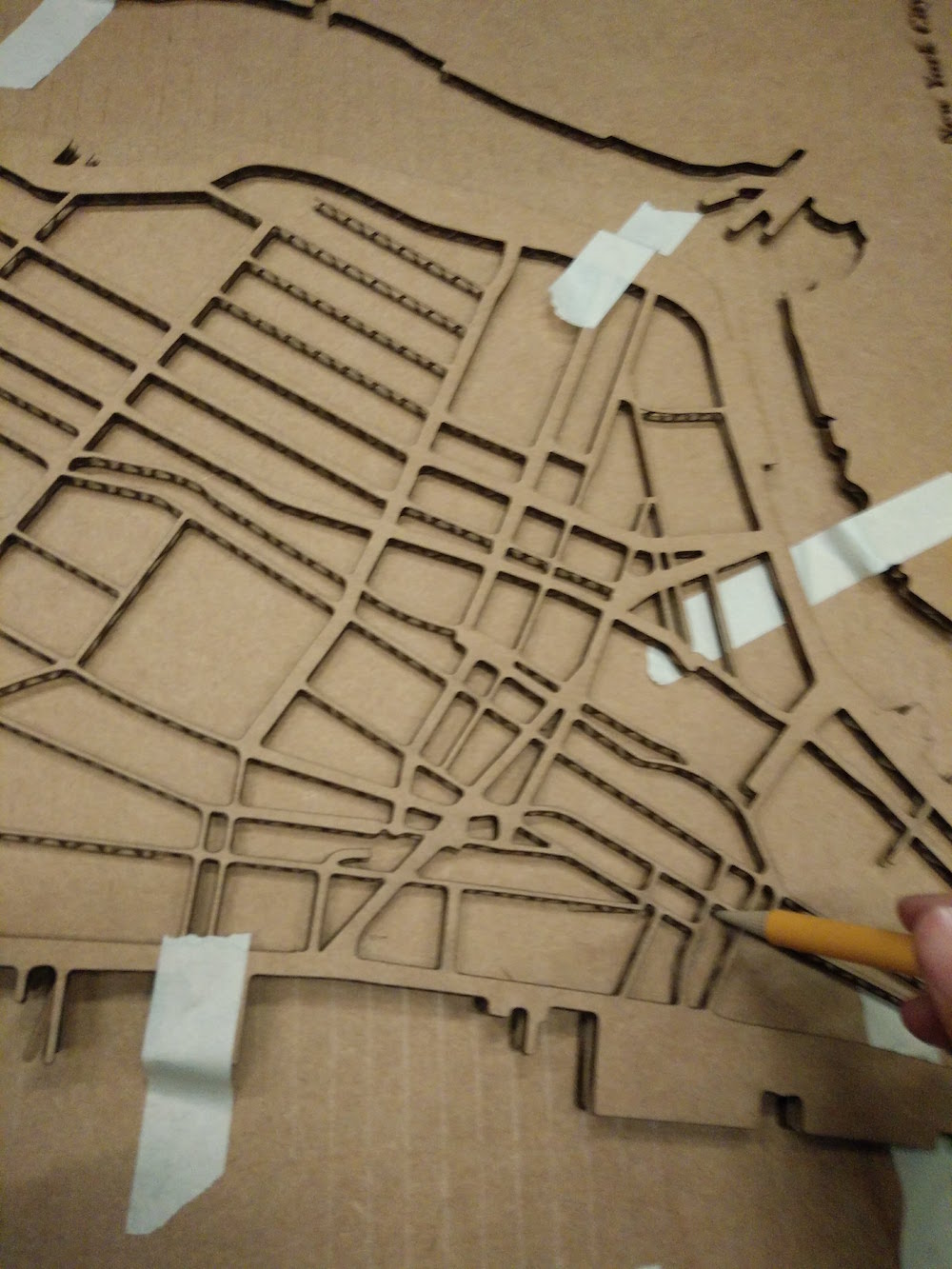
I then used a drill with a 1/16" tool to make holes in the sheets. I made four holes for each building to pass the RGB,ground wires. I did some eyeballing with how the LED's got cast to be able to do best positioning, since some LEDs tilted during the casting process.
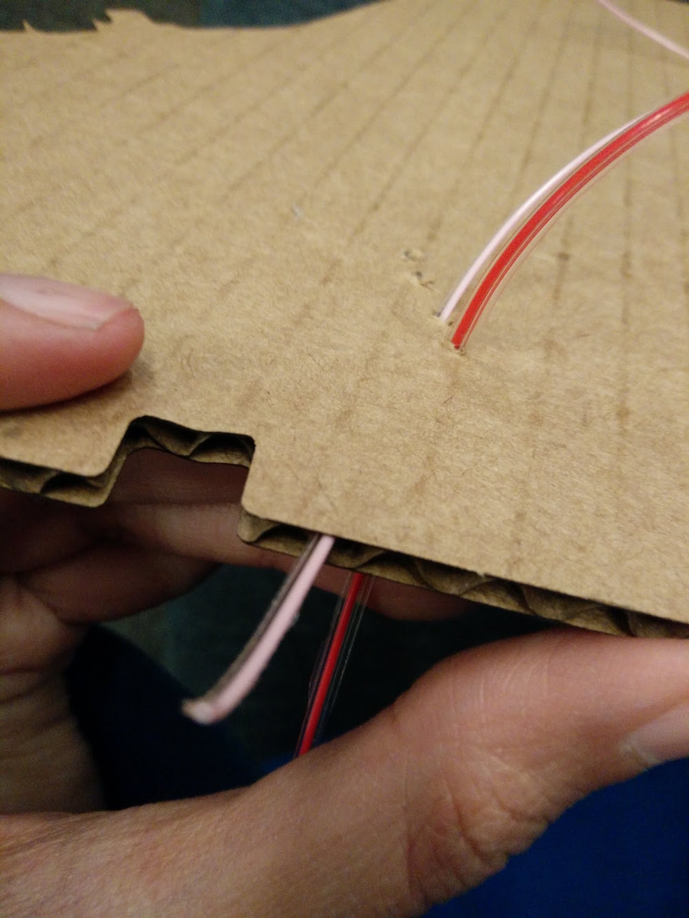
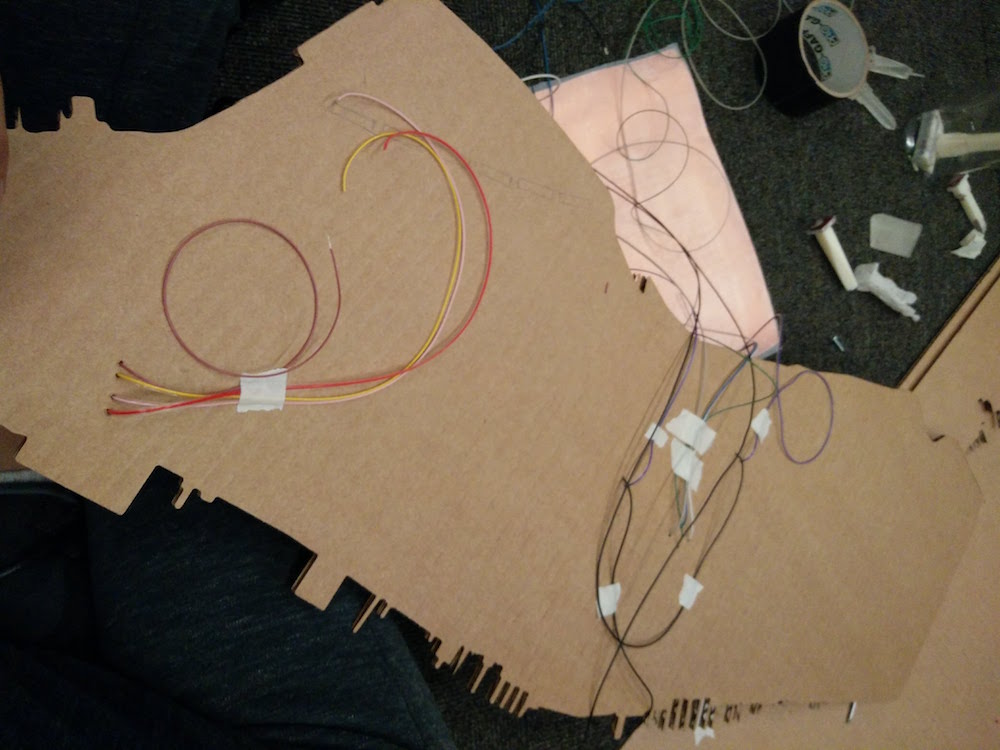
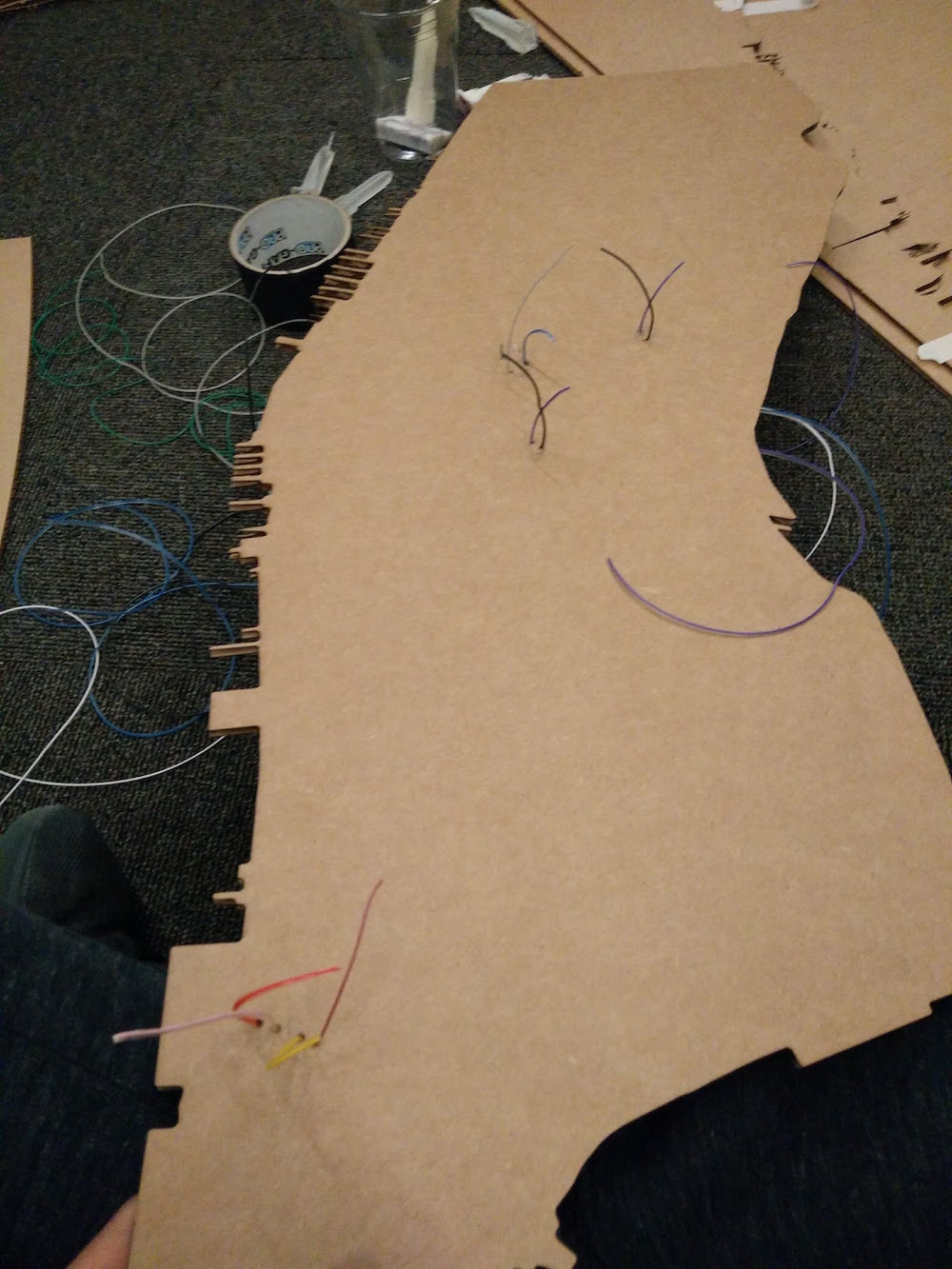
Once I slide thin wires through these holes that I drilled and temporarily secured them on the back, I stuck the vinyl cut copper traces on the front map part. These were done to the dimensions of the buildings that sat - so that it is unique for every building that sits. I then soldered the top of the wires to the traces. The traces move a lot and are not secure so I glued some on. I also made similar vinyl cut stickers on the building, so that they make a sliding contact with the traces on the cardboard.
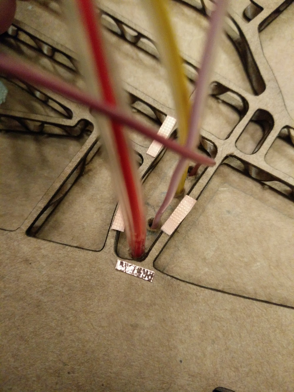
This setup was especially tricky to debug when one of the LEDs was not working. I had to tilt the board at angles, secure it, and reflow the solders. But it was also fun to solder on such a huge board.
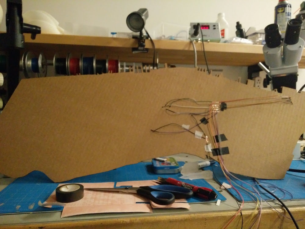
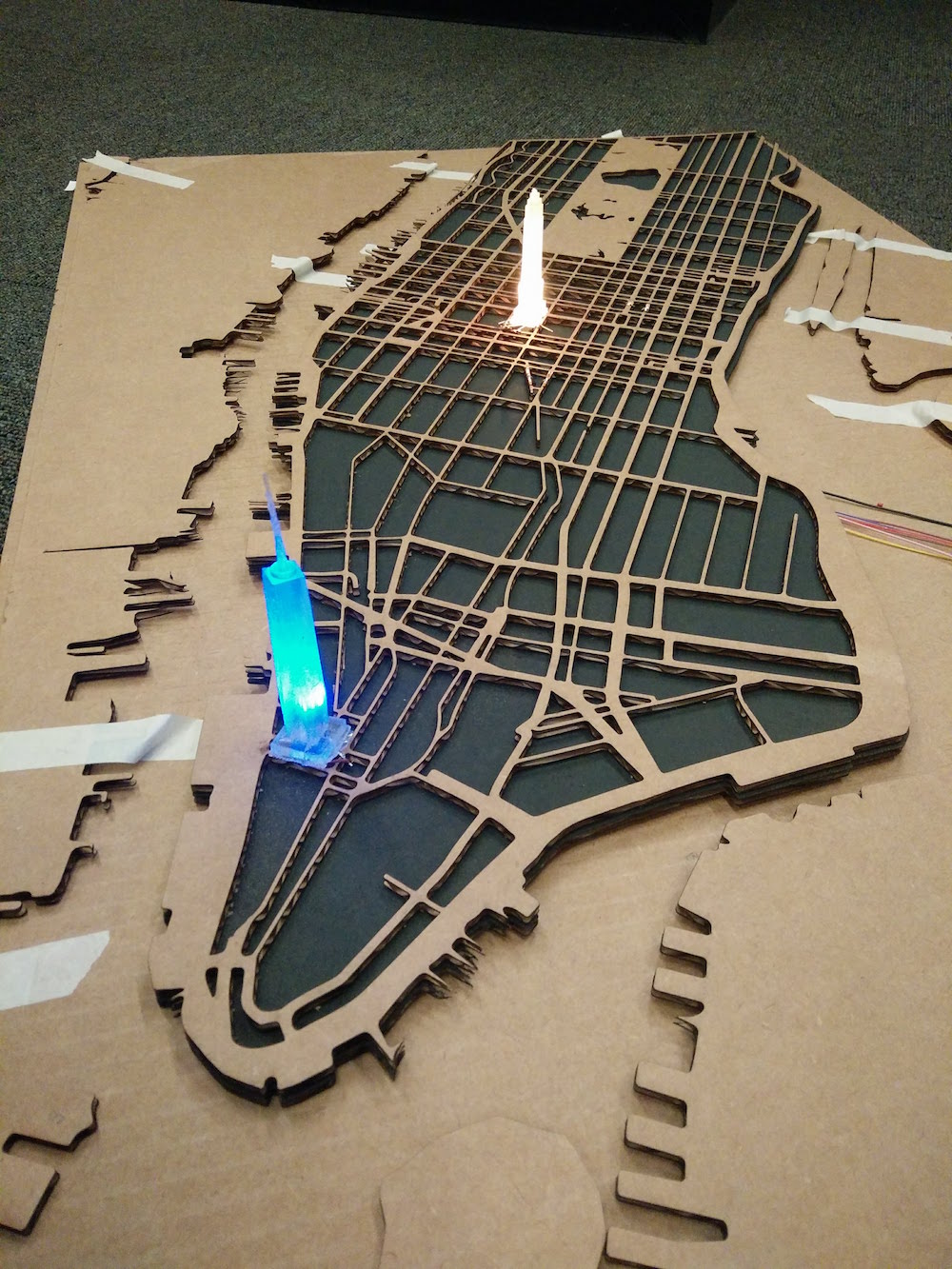

The buildings did light, and I double checked if all RGBs are working. This was my soldering setup.
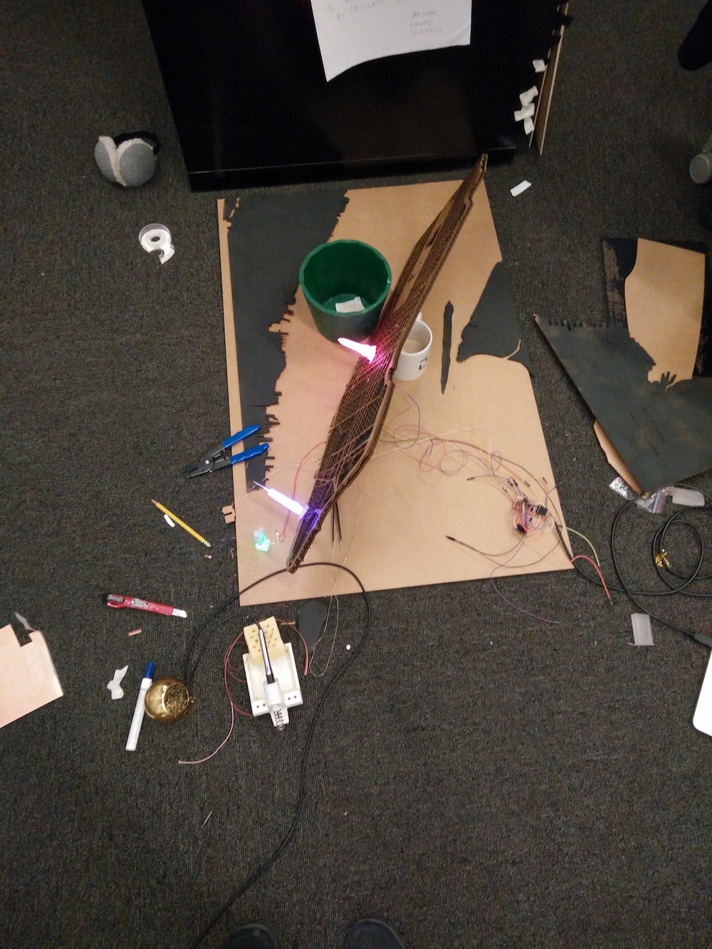
I also used 2 female 2*3 header coverters to pass the other end of all these wires so that they could go on my male 2*3 header pins on the board. I then trimmed off all the wires so that the board just fits below the cardboard and is concealed. I also put a black vinyl cut sticker on the part where the wires cross the river, exactly in the place of the Brooklyn bridge, so that it gets concealed too.
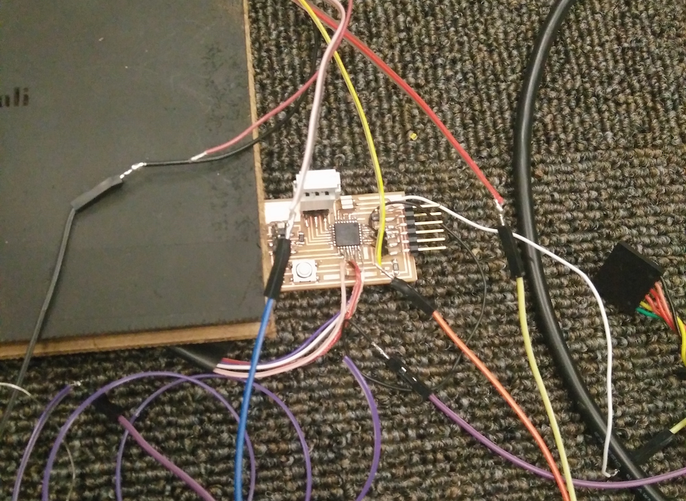
I externally tested each of the buildings before putting them on the map traces. I tested with the fade effect, and color changing, and how the transitions will happen. These are mostly different variations of how the RGB increment, and how the brightness changes. I also discovered a fun thing, that instead of grounding the ground pin, you can power all the RGB pins and then send different powers through all of them. The power of each determines current flow and leads to cool effects inside the translucent casts. See some videos below.

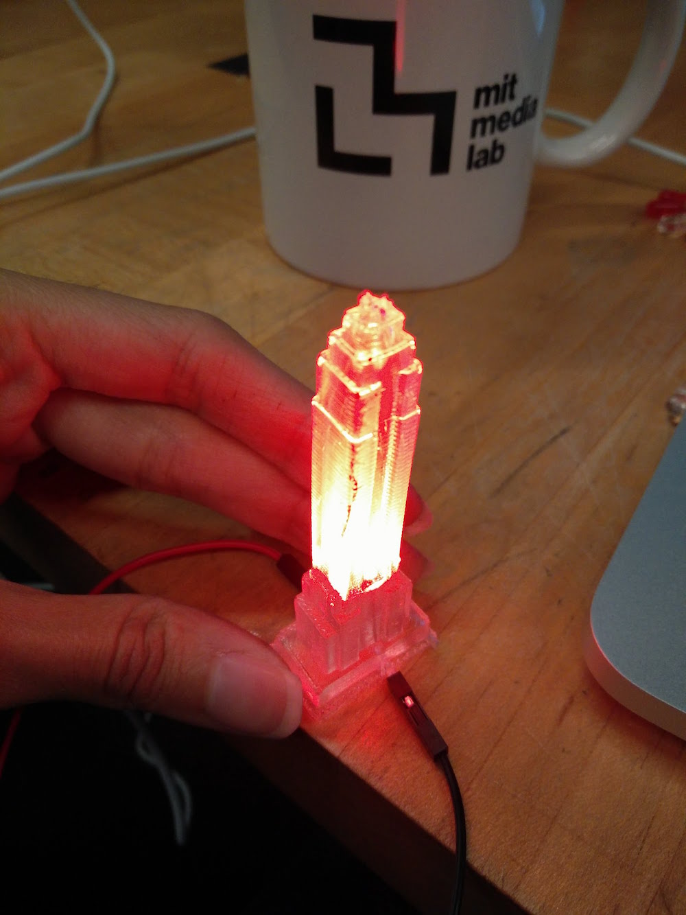
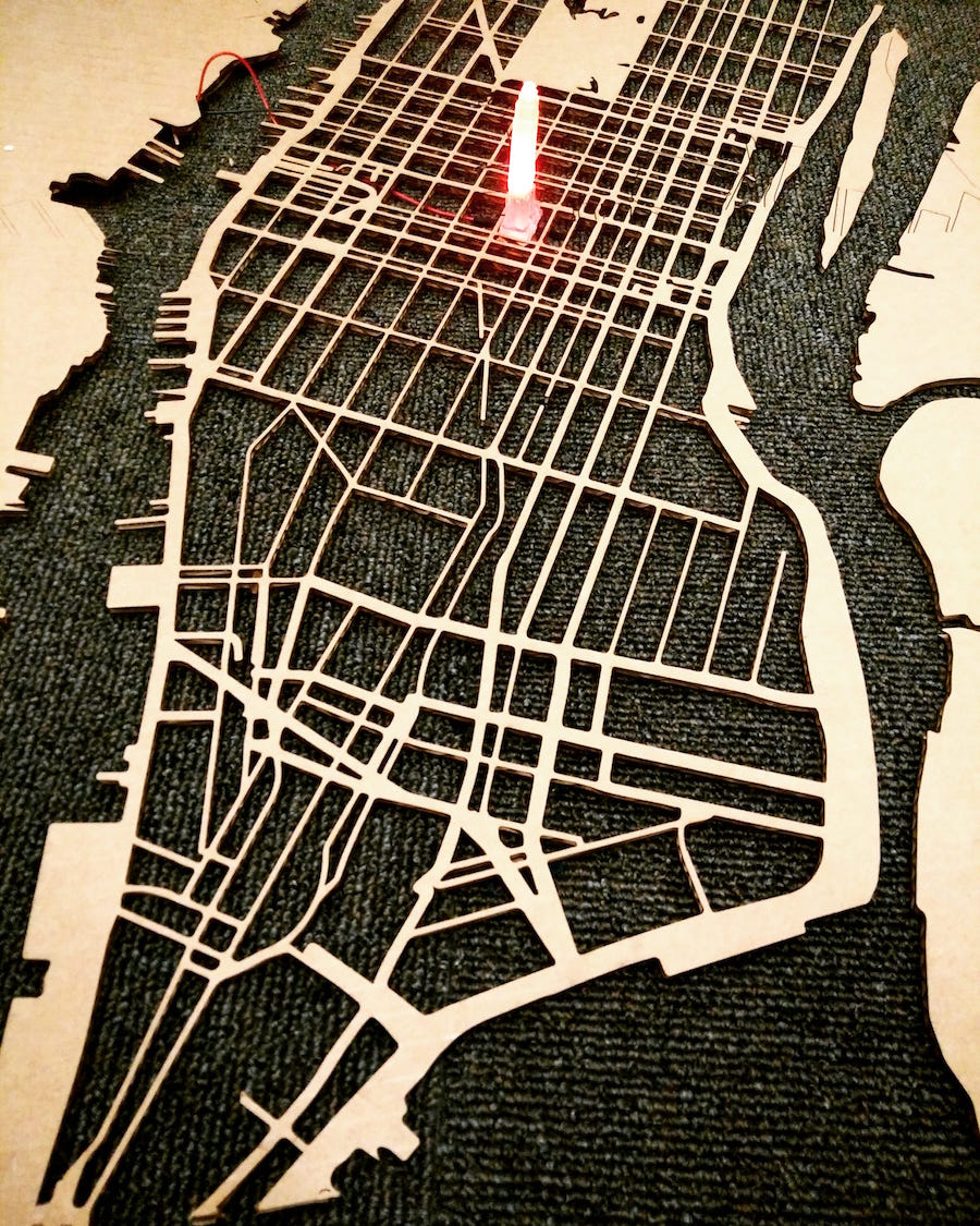
This was the part that I was most afraid of, but turned out to be the simplest to do. Captures below are two different traffic patterns depending on the amount of traffic in different locations of the city.


I used the colors of the LED to depict the vehicular traffic in the city (Red is high, Green is low), and the flickering patterns to depict the instagram posts (fast is high). For traffic, I used the 'traffic incidents' attribute of the Bing API, because actual luve traffic APIs isn't freely available. I plugged in 1 location using coordinates of each building. This is not the best way to find traffic - ideally you must pick two points, and monitor flow. If you want ot do that, Google provides a Google for work API to do that. The less tricky part was doing the Instagram API calls. I hard coded hashtags for each buildng (example, #emoirestate for the Empire State Building), and looked at the count of the tag. To find the frequency, I looked at the count difference after every 1 minute. If you want greater accuracy, make a more frequent call. Here is a good documentation of what you need to do to get Instagram requests running. For my purpose, the End Point I was using was Tag. More specifically, I needed a GET /tags/tag-name. (Here the tag-names I had were only 6, and fixed). Also, for the purpose of finding 1 minute differences to get frequencies, you can also do the recent media requests - GET /tags/tag-name/media/recent (which would not be totally accurate if you're doing it for something that changes drastically in one minute, because the cap the amount of media in recent). Note that the scope of this query is only public content (so this doesn't take into account private accounts). You can, however, search for your friends, which would be a fun project too. The parameter we are interested in, is COUNT (Count of tagged media to return.)
I did the shabby thing of writing this count to a text file, and having my Arduino code read the text file to get an integer value. After multiple rounds of playing with differnt light combinations, I did a color setting of my RGBs to :
setColor(trcolor, 255-trcolor, trcolor+50, 0);
the trcolor value starts from a value I get from traffic, example, it's high for high traffic, so the R value is highest. It increments at the flickerrate :
trcolor = trcolor + flickrrate
. I set the delay to 50 to make it look like a real flicker. below that looks like a fade. I also set bounds on the trcolor value through the flickrrate so that it doesn't go out of bounds, by reversing the direction of flickrrate at the end, so that it follows the opposite direction :
if (g <= 0 || g >= 255) {
fadeAmount = -fadeAmount;
}
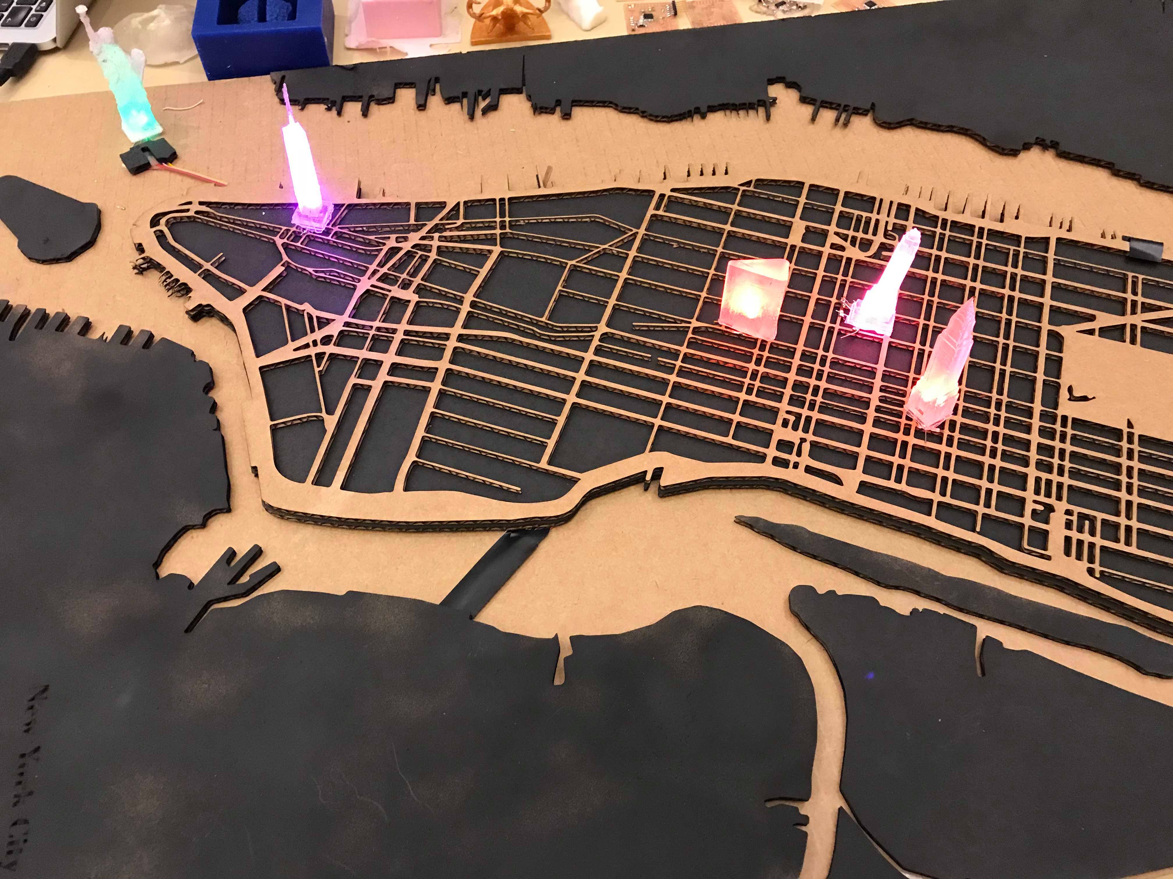

Below are the videos of the final map. Not captured in the videos is how you can lift and place the buildings to make them loght up, mostly because Ileft town before documenting this part (it was demo'ed) and realized I don't have a video of that. More to come!
My main learning for this project was that if you need to do something that involves 3d printing, and molding and casting, you need to start very early. This is because : 3d printing ~ 12 hours (more when models fail), dissolving support structure ~ 8 hours, Molding ~ 24 hours, Casting ~ 2-3 hours. Also note that with casted electronics, when something fails inside, you have to redo the whole thing. So make strong molds so that they last for multiple casts.
Super thanks to Neil & TAs for all the guidance. Thanks Tom and John. They were so incredibly helpful and patient. Grace taught me a bunch of interesting casting techniques. She also suggested cheap material, and ways I can make my molds better since they were so small. She also, pretty early on, discouraged trying to do epoxy and composites for this, and that saved time. Prashant helped me with an initial electronics design week, which later helped me debug electronics. Thanks to Stefania, Anna, Agnes, and Sean for lending me some LEDs. Thanks to Tomas, Vik, Agnes, Emily, Anna, and George for the fun company while building. Thank you for reading!
Yay, making things open source. I imagine the vector maps, building models, Mapbox style, and QGIS files would be useful to other makers, so linking them here
Laser Cutting
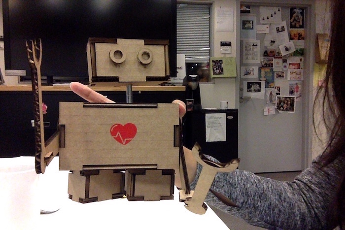
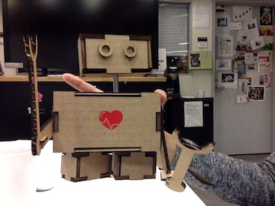
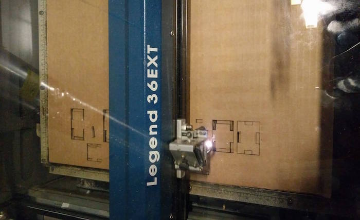
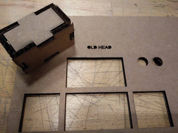
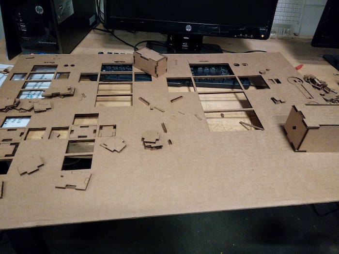
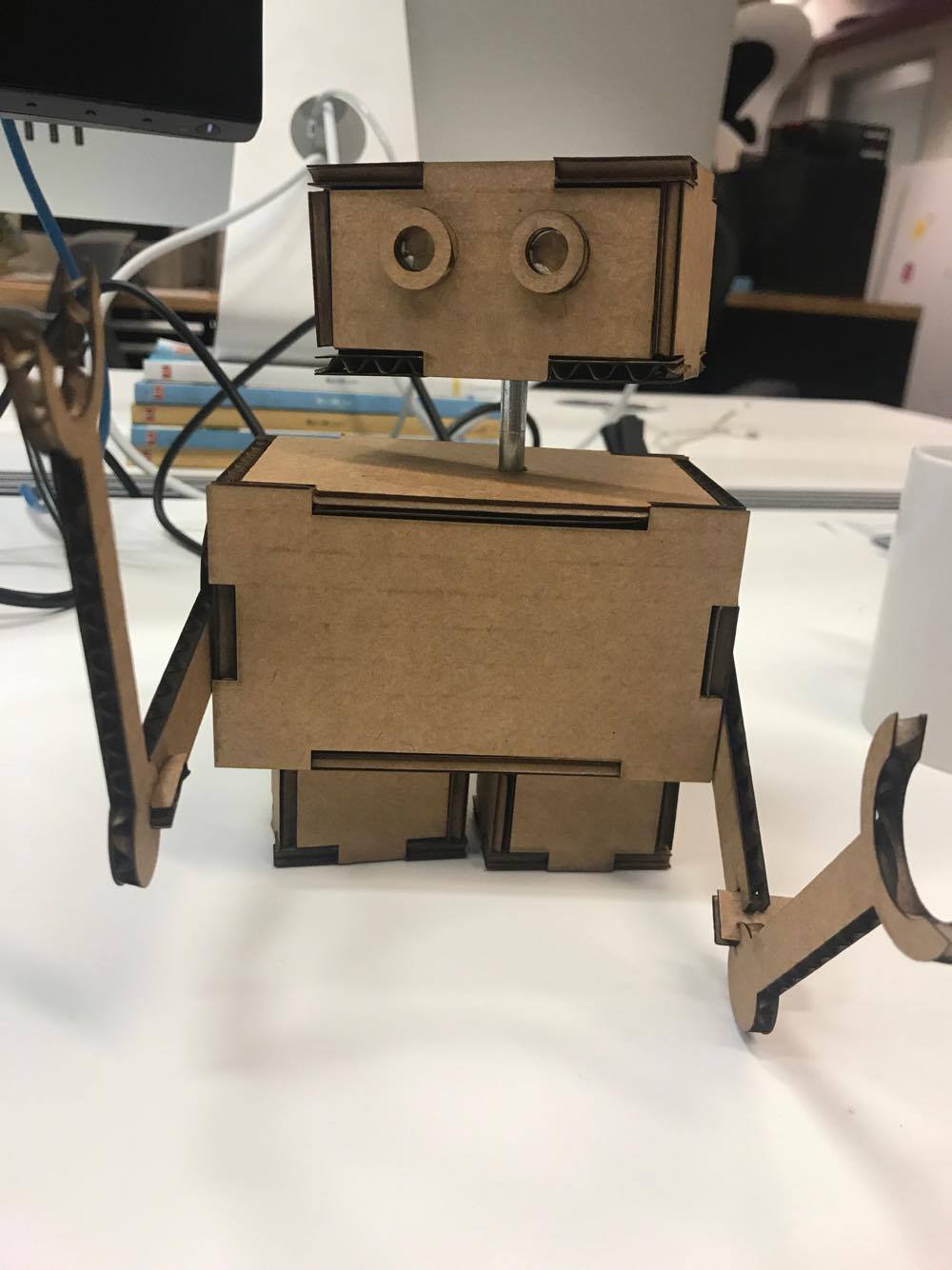
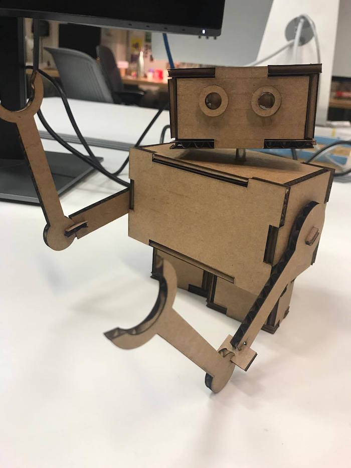
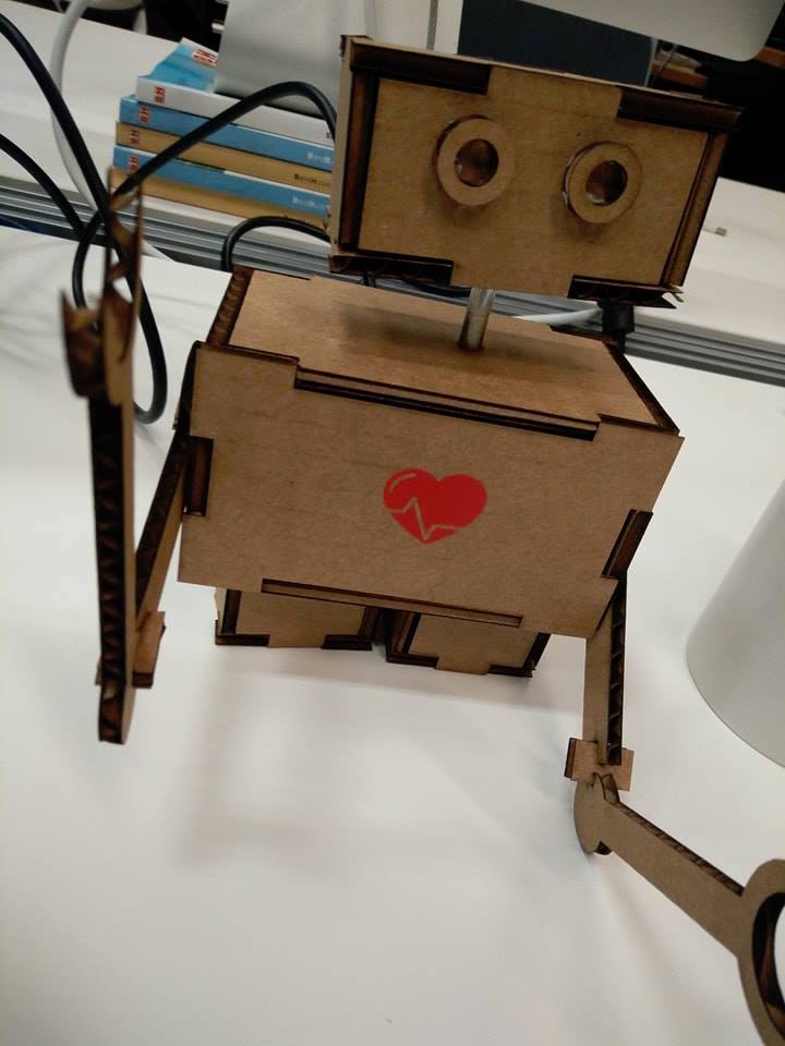
This week's assignment was to use the laser cutter to make a press fit construction kid using cardboard. I decided to make a tiny robot structure that could change its height and rotate its arms and head.


Vinyl Cutting
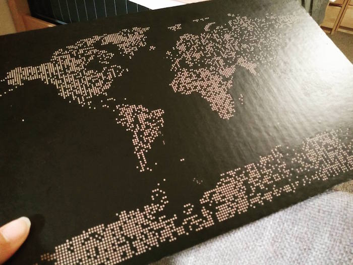
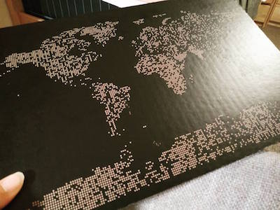
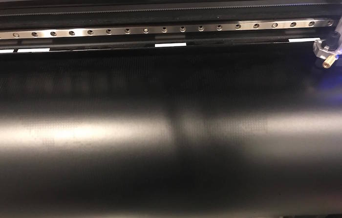
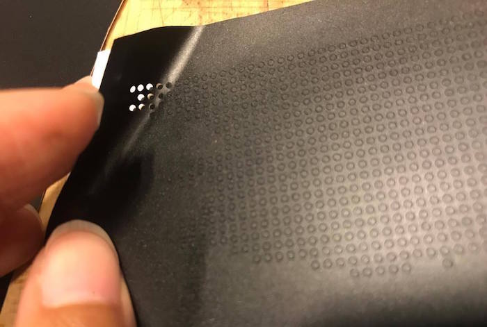
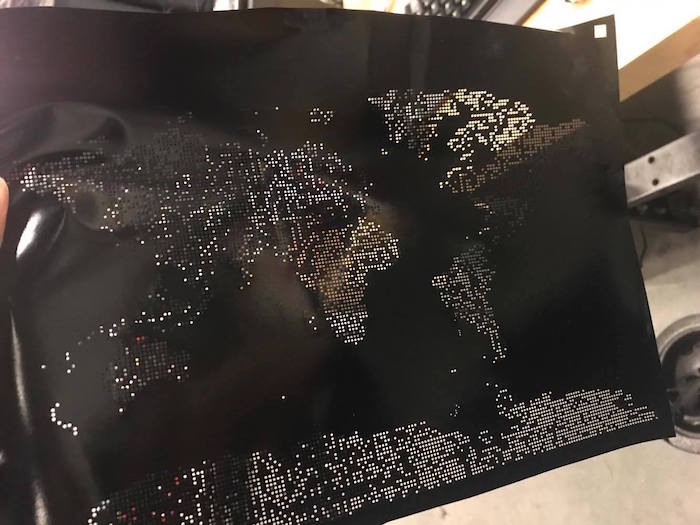
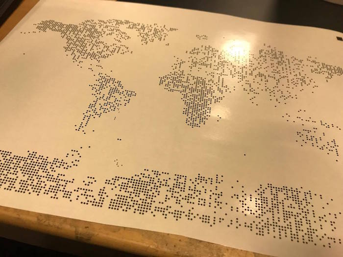
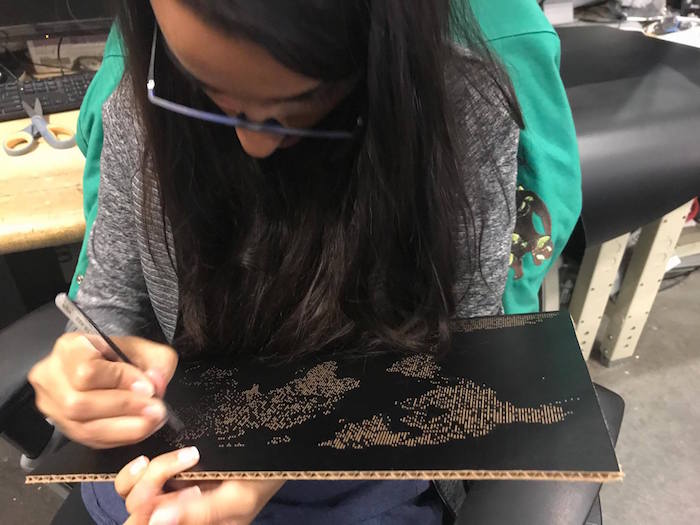
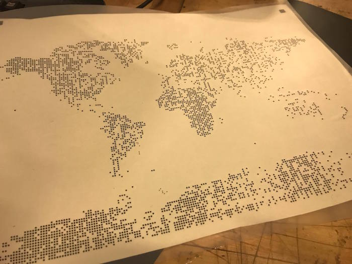
This week's assignment was to use the Vinyl cutter to cut out a sticker form. I wanted to create a world map made out of dots, and make it functional by having multi-color dots for the places in the world I have visited.

I first used Illustrator to make a huge dot grid. Then I took a vector of the world map shape and made a Clipping Mask on the dot pattern structure. This gave me a dot pattern world map. I then changed the color of the dots corresponding to the places I had visited (red dots).
Electronics Production
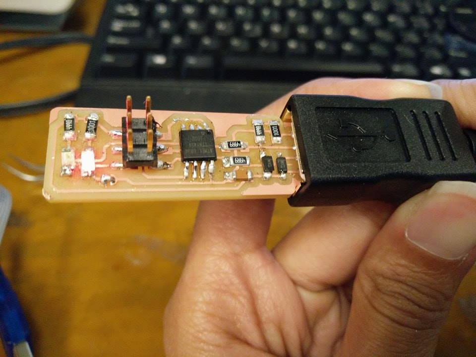
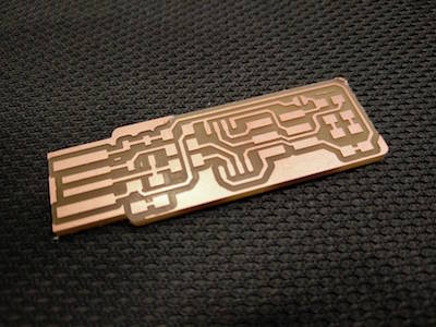
This week's assignment was to make an in-circuit programmer by milling the PCB. The group assignment was to characterize the specifications of your PCB production process using a given trace width file.
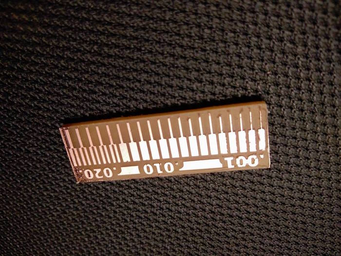
We were first taught how to use the milling machine by the very helpful TA, Andrea. She told us about what mill heads to use, how to ensure the base board is aligned correctly, and the pcb board is mounted correctly. We first used the milling machine to cut out the trace width file. First we milled the traces, and then we used the milling machine to cut out the outline. It came out well the first time, except, as you can see, there is some extra conducting material remaining, we scraped it off using a paper cutter.
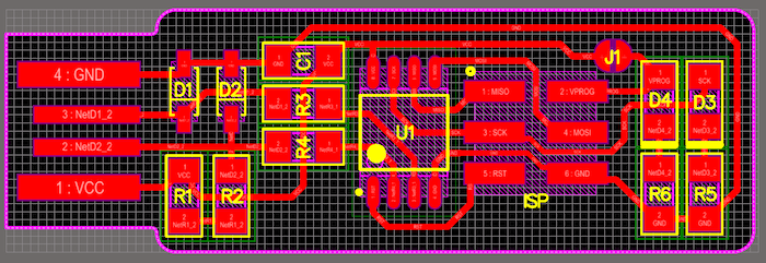
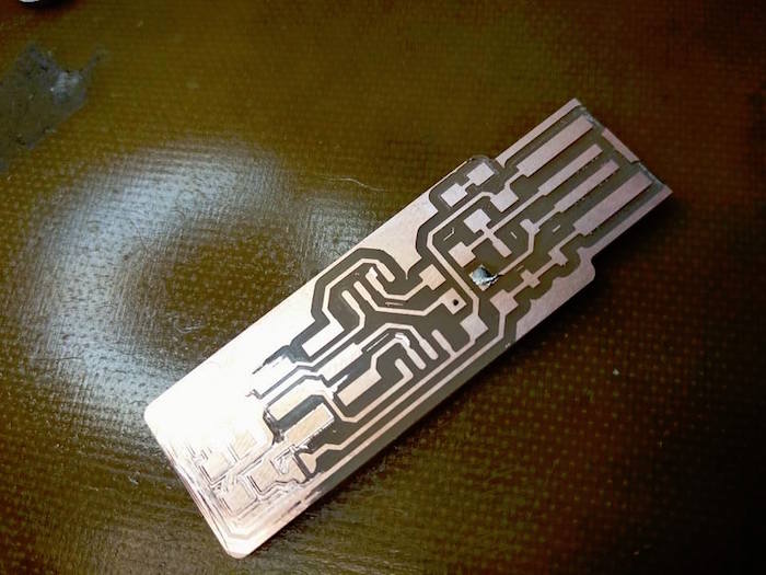
I used the PCB traces and outline file provided in the class document by Brian. I then used the Milling machine to try to etch the board. The first attempt of my board did not print well as you can see. One entire side did not mill off well. I realized it was a combination of not pressing the board to the base and not pressing the mill head to the board.
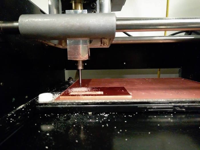
The second board turned out okay. I used Mods for the first time, and it was pretty easy to use for milling. I also realized that you can run only one instance of Mods at one time.
The next part was the soldering, and wow - it took so much longer than I thought. The solder kept sticking to the soldering iron tip, instead of the parts and the board. Tomas then suggested to me to use the magnifying lens. It was much quicker with the lens. I think I did a not-so-neat job with the soldering, but got a lot of practice. I also did the resistors (horizontal instead of vertical) TWICE! Pro tip : It helps with patience if you work with other people, thanks Vik, Emily & Tomas.
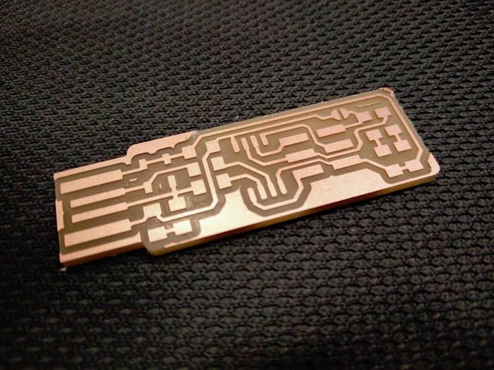
Once I was done cutting the board, I used the ATAVRISP2 programmer to program the board. I used the class tutorial instructions and everything went smooth with the programmer and it worked out.
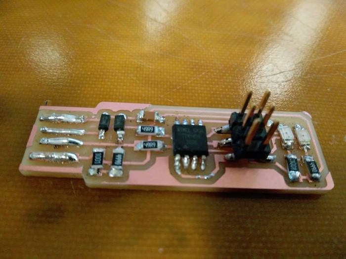
I then ATtiny45's reset pin into a GPIO pin by running the 'make rstdisbl' command. I then disconnected the Vcc from Vprog pin by removing the solder bridge (yay for copper braids)
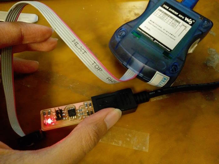
I now plan to make another PCB on a 3D surface and program it using my board.
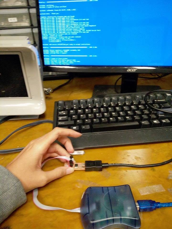
3-D Printing and 3-D Scanning
This week's assignment was to 3D print an object using additive 3D printing method, and then to 3D scan an object. Shout out to Tom & John for teaching us how to scan, and special thanks to Tom for patiently printing our models (and offering to redo mine that broke in the water jet). I was mostly excited to 3D print an object that cannot be made subtractively - and I had a grid lamp project in mind that I saw here. I used this tutorial to learn how to convert an image of a deer to a low poly model in blender. Since I decided to do one side and keep it symmetric, it was easier than I thought. Note that you can just use 'Simplify' modifier to increase the complexity of the model you want after you have created a very basic outline of the low poly. This is also an extremely common deer model, so you can find any deer model and convert it to a low poly model using the tutorial linked above and using Simplify.
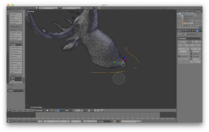
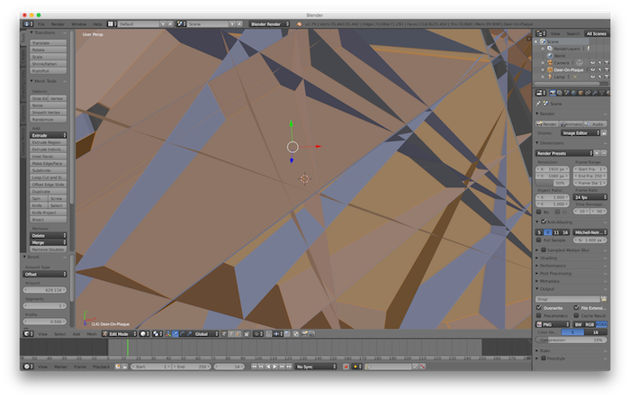
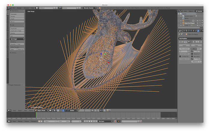
The final aim was to try to create a grid like mesh of the deer so that I can add a lamp holder inside the mesh. This step wasn't as simple, but I used the wireframe modifier in Blender. This assignment taught me more about using blender than about 3D printing. This is an image of everything going so haywire in Blender, that I had to screenshot.
I could finally get the mesh to work, and removed some vertices to create a full closed mesh. I was super under confident about if the printer can print it, so I just saved a full solid model of the deer also, and sent both to Tom for printing, as a backup.
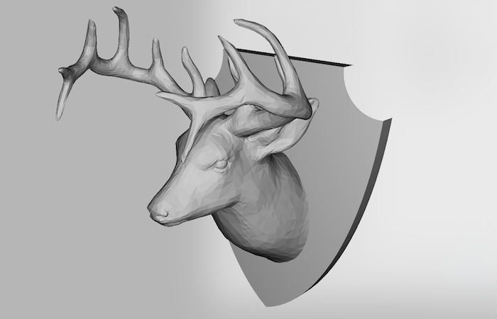
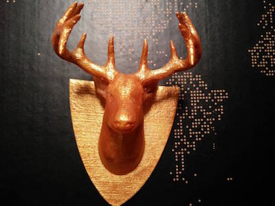
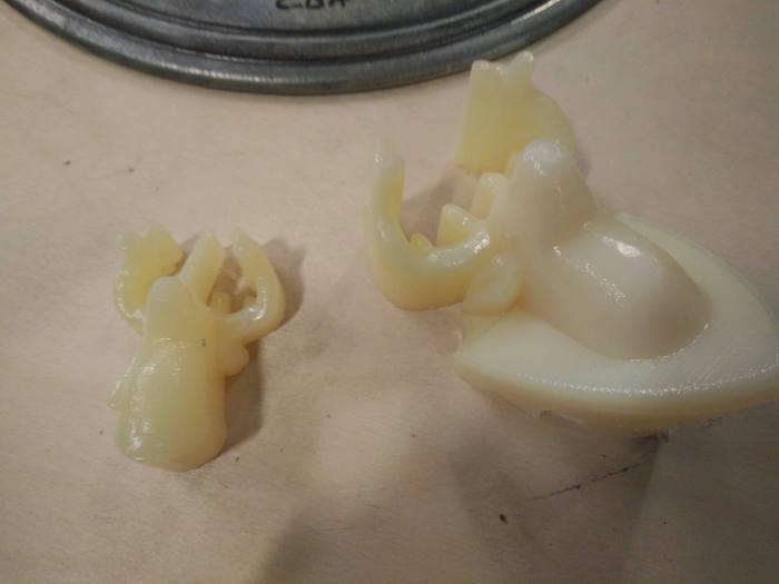
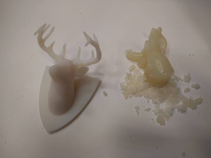
And here you can see both the outcomes. Tom warned me that the mesh model is so delicate that if you try to remove the supports, it will break. And right he was. On the right is the solid (backup) model. In class, I spoke about my failure to print the mesh model, and learned that I must use a thicker mesh, and a bigger model. I thought it was cool how delicate some of the prints in class were!
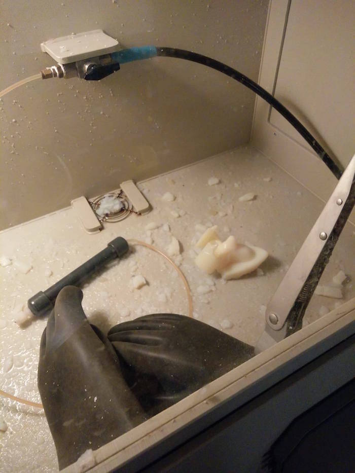
I used the cool water jet machine to clean the supports from the solid model - however, it broke a little bit of the back plate on the deer. The water jet was apparently too strong. Tom suggested, you can just super glue it later, and also suggested that I should not remove the rest of the support with the jet, and can just do it by hand. So here is me removing the supports by hand.
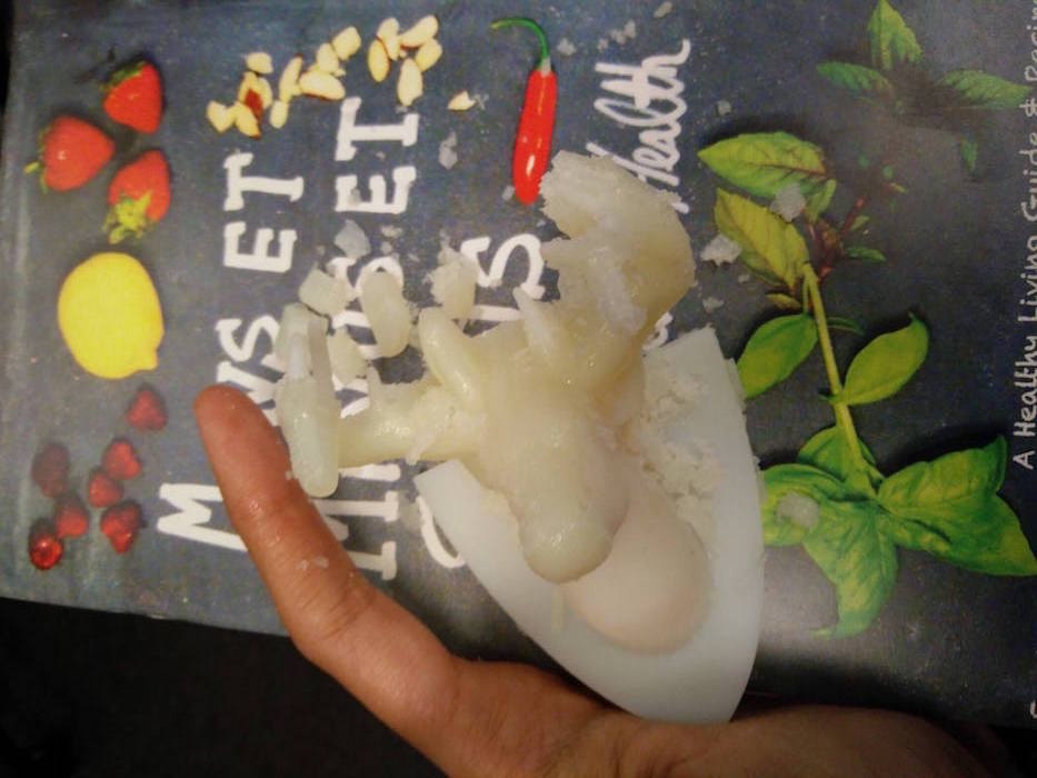
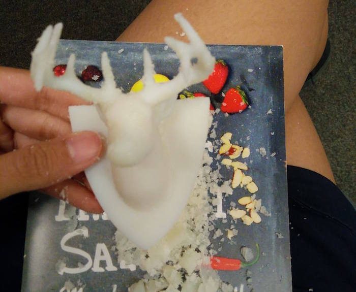
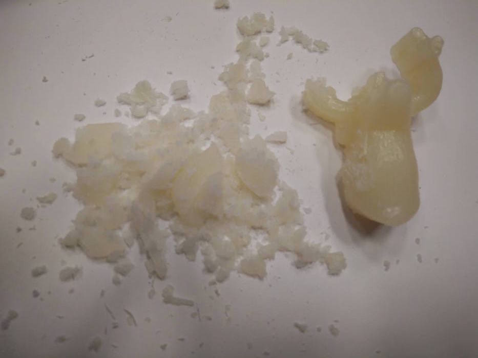
The other model (mesh model) just came apart as soon as I started to remove the supports. The mesh was very very weak, and not even separable from the support material. I realized that was in vein, and stopped removing the support. Failure of mesh - but I could get some tips about how to make it stronger in the future : 1. Make the model bigger, 2. Use thicker mesh widths, and 3. Use fewer lines for the mesh. It was fun to learn to make the mesh digitally anyway.
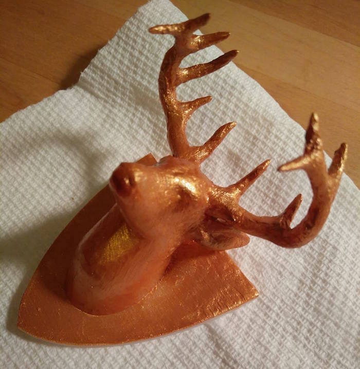
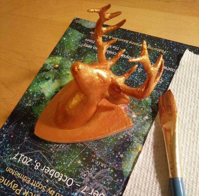
I then gold painted the solid deer so that I could use it as room decor.
For the 3D scanning segment, I scanned my friend, because I really wanted to create a tiny human. I used Sense 2 to scan. It kept losing contact, so I could not get some parts correct, but I figured I can post process it and clean it.
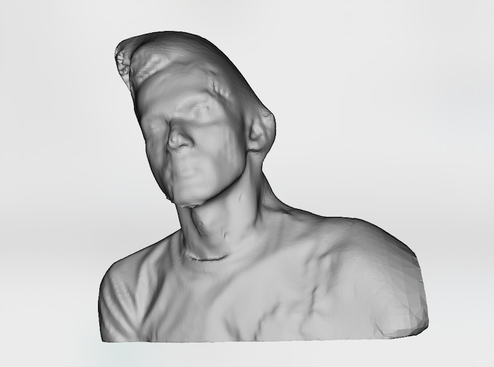
I used the edit mode in Blender to remove the vertices from the parts of the model that I did not want. It was a fairly complicated process. I was looking at more simpler ways to do it, and tried using the sculpting mode, but that was strange for so many vertices, as it doesn't really remove the vertices, so the plains just come out on the other end, so I reverted to edit. I do know that there would be better ways of doing this just by sculpting, for which I am watching more sculpting videos on Blender.
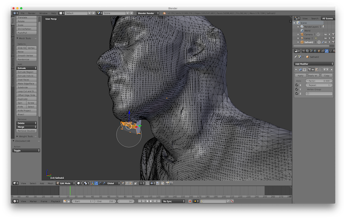
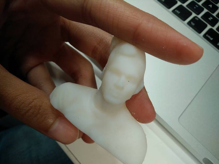
I then printed the 3D scanned model of my friend. I had a little friend now.
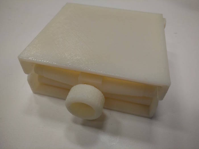
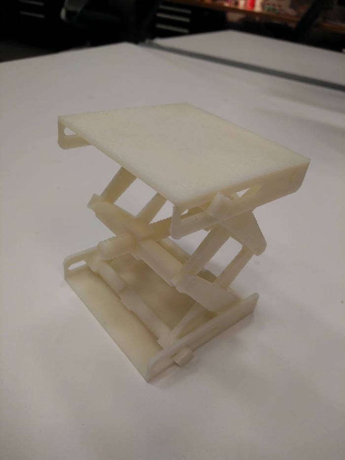
In order to print something additive, I went back to thinking about shape changing mechanical machines, and thought about making a height changing rise jack. It used a screw and has slots to change the height of the jack. I had created this design in the past inspired from a Thingiverse Jack - where a mechanical design is used to change the degree of freedom to raise the platform, but I wanted to take up the challene of doing it in one go, without printing the parts seprately (also becuase I had access to lower end machine and doing all parts together was seeming tough). I also made really small jacks with separate parts (could not make them in 1 part since the material sticks together). I could get it to work fine, and the platform does change height upon manual rotation of the screw. The rotation can simply be done by a motor and we can change how big or small a character is.
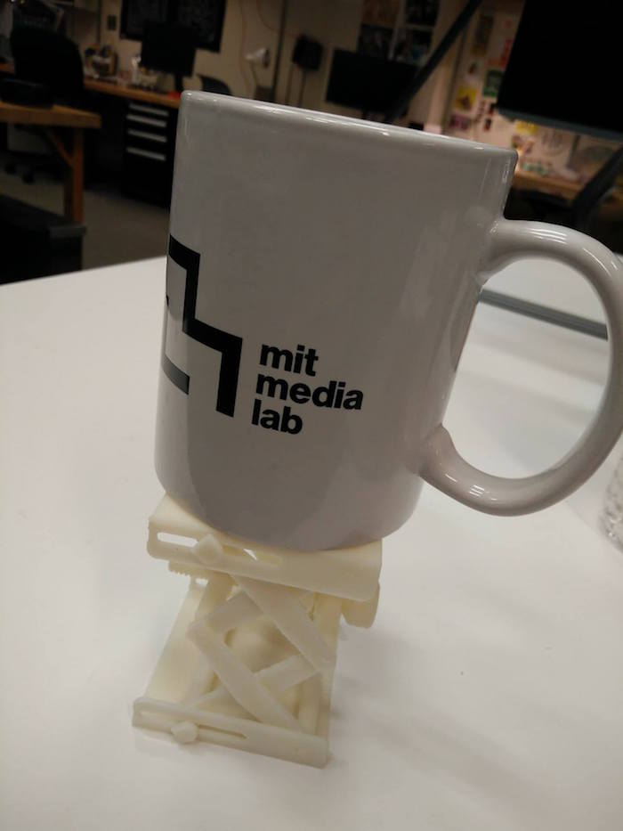
Electronics Design
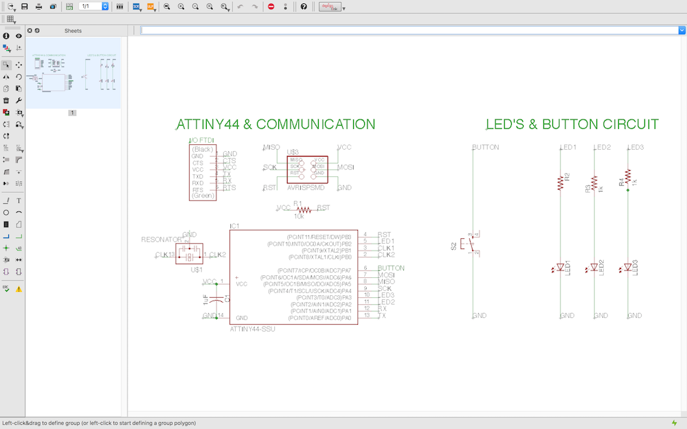
This week's assignment was to draw our own board starting from the Echo hello world board and adding components to it (>= an LED and a button). Learning agenda for this week was - a. Designing circuits (using Eagle or other similar drawing software), b. Making them (Using milling or Vinyl Cutter), c. Testing them (Using testing equipment such as Oscilloscope and Multimeter.
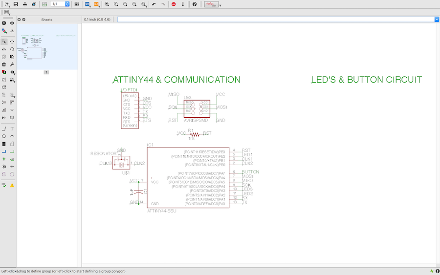
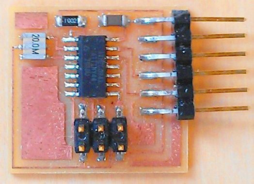
This project was my first attempt with Eagle. I started with the Echo hello world schematic that was provided on the fab class assignment page. In addition to that, I also used the Libraries provided for the parts I added. I was using the Attiny board, as used in the hello world echo board. I first started by adding a button and 3 LEDs to the three available pins on Attiny 44. The aim was to program the board to light up the three LEDs sequentially. I used electronic parts from the Library provided by the class. I chose 1 button and 3 LEDs (with 1kOhm resistors) and dragged them into the schematic view of Eagle. I also leard using the Eagle command line, which made my life much easier to label and connect parts. Extra thanks to Allan for being patient with so many Eagle questions.

I went on to the board view to draw the board. This took so much longer than I thought, since I also wanted to keep it small and compact. Eagle is slightly non user friendly to use for drawing wires, but it has a bunch of useful wire type options on the top.
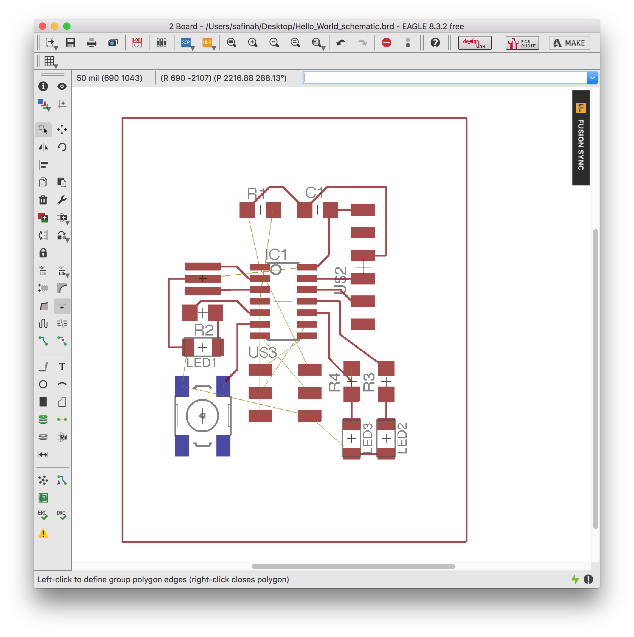
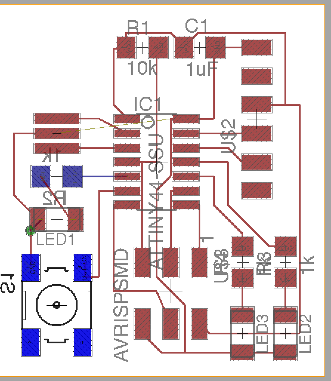
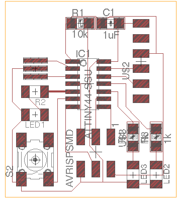
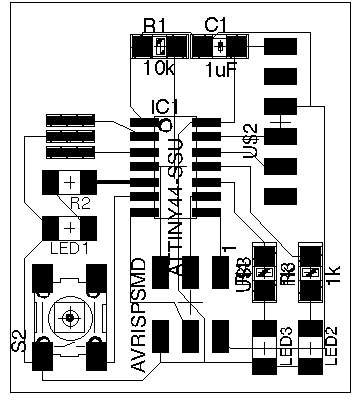
It was helpful that Eagle allows what dimension of grid you want, and what the smallest unit of motion will be. It took me a while to find these options. After I was done connecting the parts, The next step was to set only the top layer as visible and export to a monochrome png. Every time I tried to do this, some connections went through the board to the other side, and would not be visible. I got very confused about what is happening and even asked the TAs. I later realize that this was happening since some of my parts were on the wrong side of the board. I also realized that mirroring any part shifts it to the other side of the board. Allan mentioned that the quickest wya to fix this would be just recreate the parts - and I did exactly that and it was fine. I finally exported the board traces and outlines as monochrome PNGs.
By this point I was slightly bored of following instruction and wanted to create something of my own. I thought about Schaad's beautiful board that Prof. Neil spoke about in class, and wanted to create something beautiful myself. I looked up some work other people have done, and found that there is a company called Boldport that makes beautiful circuit boards and kits. I got very inspired, and wanted to create a Lion Head artwork with my circuit. I also decided that for this assignment I want to use a non-milling machine way of board production, in order to know more ways of board production (since last week I used the milling machine). I also wanted to avoid the frenzy around limited 1/64 bits. So I sought to explore the Vinyl Cutter for making my board. I remember Prof. Neil tell other students who used the cutter in the previous classes for circuits to use thicker traces - and kept that in mind.
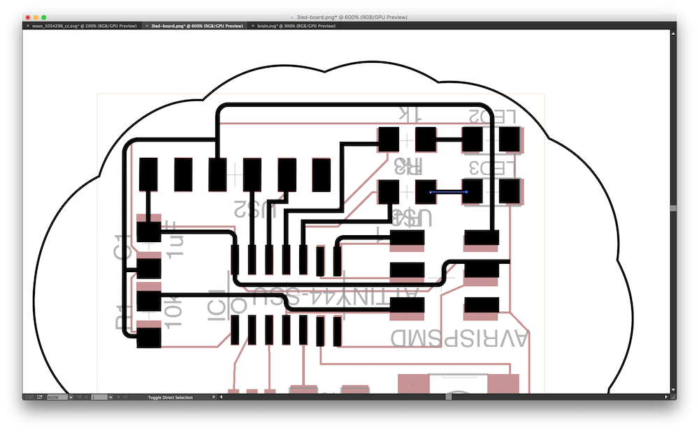
To create my artwork, I first exported the board image I had created in Eagle to Illustrator. I recreated the parts in Illustrator, while keeping the sizes of parts the same. I moved them around to see how I could change the connections to create a lion head illustration.
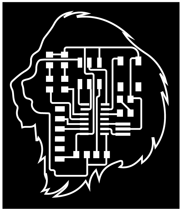
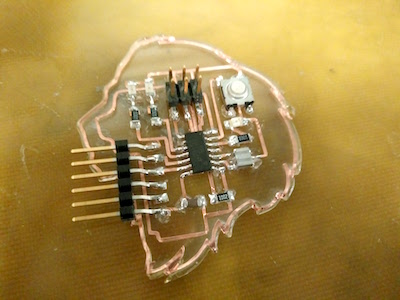
After playing around a lot with shapes, and changing a lot of the connections, I created the lion head shape above. The overall lion outline is using the pen tool. I changed the orientation of the board, and moved around some traces, as well as the outline to fit well. I placed two red LED's in the lion's head that are meant to act like the lion's eyes.
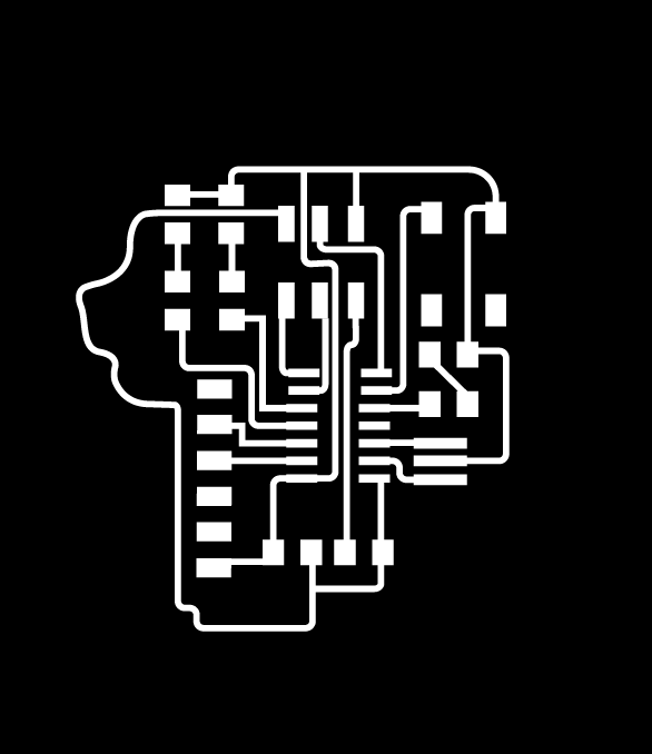

Here are the outline and traces files of the board if you are interested in milling it.
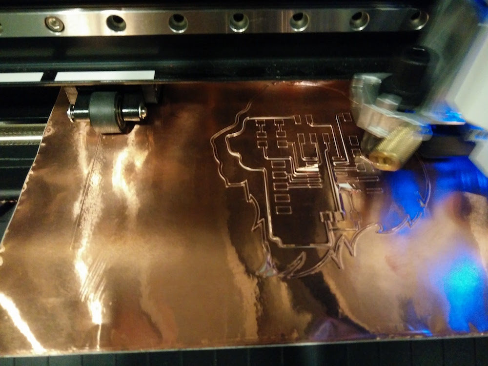
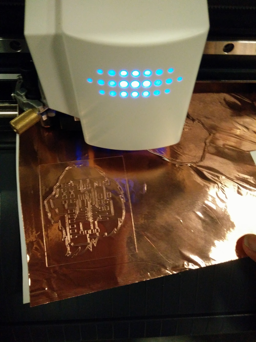
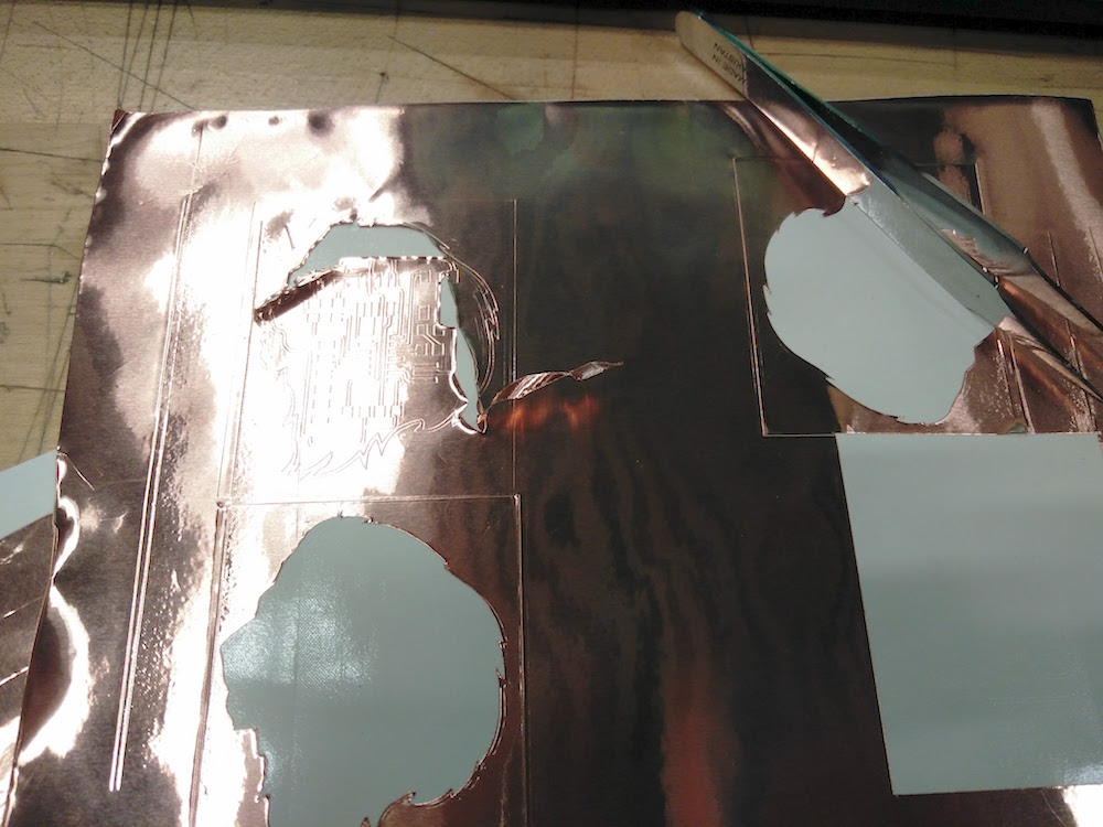
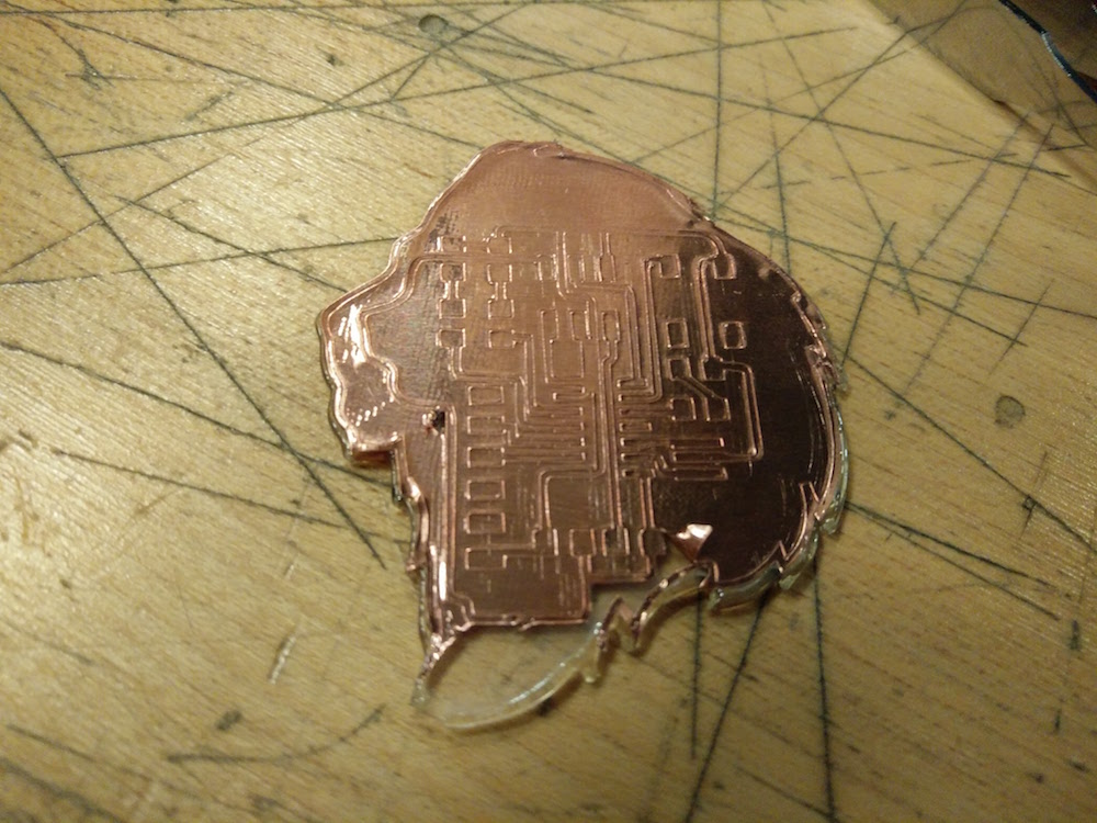
I then started trying to 'cut' the board elements on the Vinyl cutter. I had imagined the process to be 10 minutes, but it took me 4 hours to figure it out. The Vinyl cutter would keep lifting the conducting part off the paper. Burhan and I experimented with the machine on a piece of conductive strip for a very long time, and you can see some our failures above. We played arond with the blade extrusion, the power, and the speed settings. Finally we hit the sweet spot where our circuits were cutting.
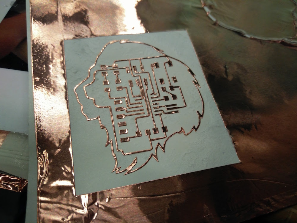
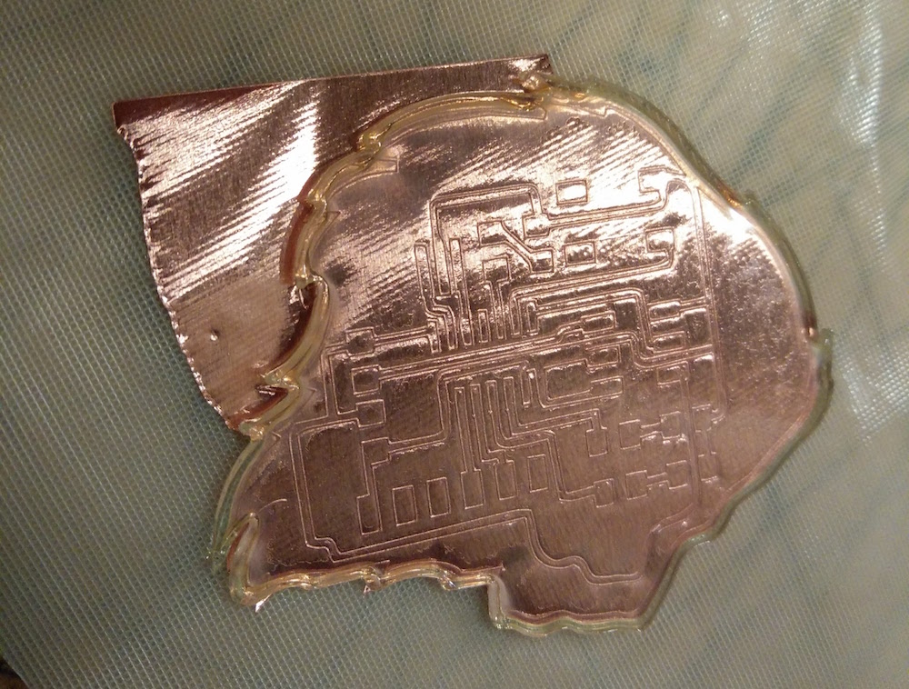
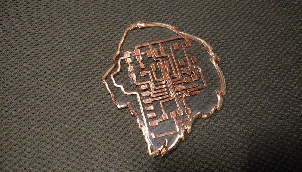
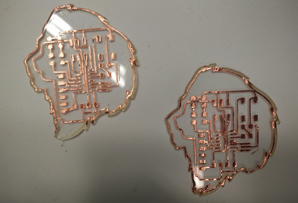
One of the things I realized early on that helped was, to not peel off the circuit from the original paper. I peeled off the entire print using the contact paper. I then laser cut a lion head on acrylic. I paster the entire lion head on the acrylic piece, and then started peeling from there. This helped the traces stay in place while I pulled the negative out. This process was quite fun. As you can see, some traces were so close that they ended up not cutting and sticking together. This could be resolved using a paper cutter, but I also printed another one to be sure. And of course I made a soldering mistake later in the homework, so the two boards were super useful.
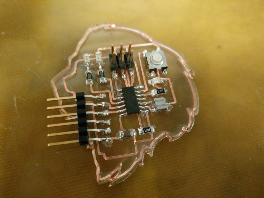
I then went on to solder the parts of the circuit on the board. This was an interesting struggle because the solder started to melt the acrylic. Most parts were pretty straightforward to solder. Since in electronics production week I had messed up with the LEDs so much, I paid extra attention not to solder things wrong. But well, I ended up soldering the Attiny backwards, and since the traces were so delicate, I just shifted to the other board (yay for 2 boards).
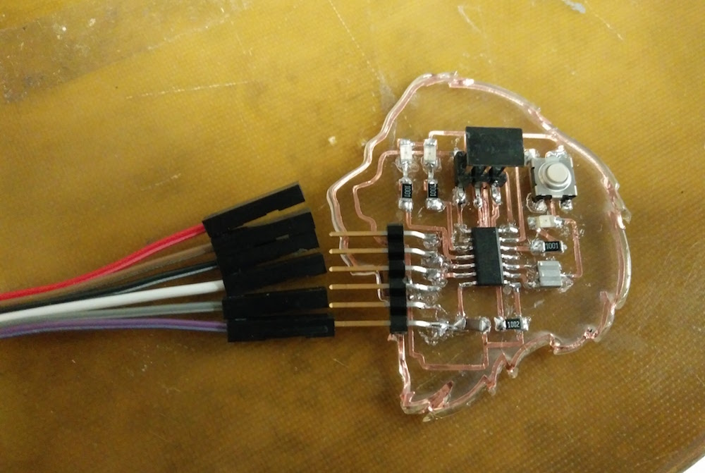
I then started to attach wires to the 6-pin header in order to connect it. One major push, and all the traces were gone. I then made solder traces, but they did not look as neat, but seemed to work.
In order to check my circuit, I re-did the design on the online simulator EDA , which was super easy to use. This week I plan to use my old board to program the new board to do the sequential LED blinking and make the lion come alive. I ran my circuit by Thrasyvoulos and they mentioned everything looks good. I also learned how to use the multimeter to check current and voltage difference and want to be able to practice that this week.
Computer Controlled Machining
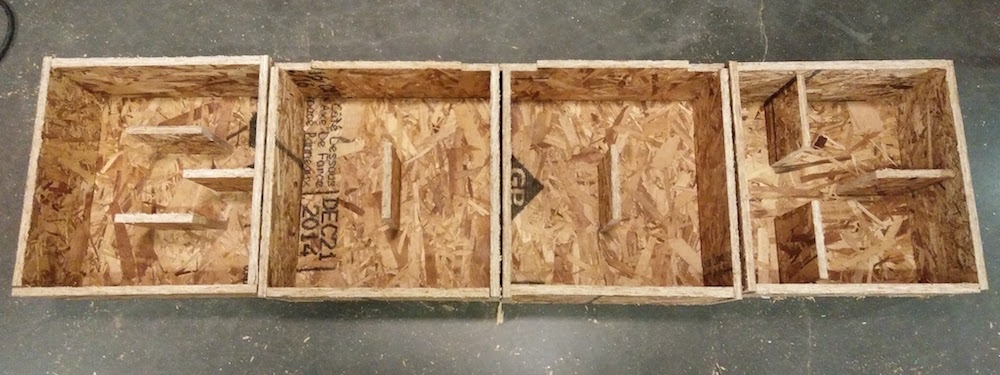
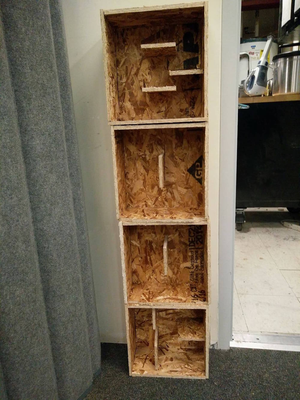
This week's assignment was to make something 'Big'. I first wanted to make a mobile house, and then my house dream crashed because the material we get is 8*4. So, I wanted to make a custom bookcase, with individual shelves that look like alphabets.
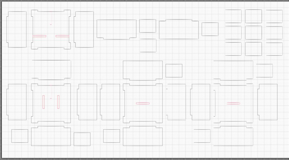
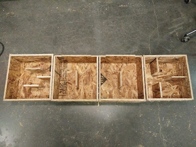
I made my cute file vector on Illustrator, because I had a pretty good visualization of what each part would look like. I made joint cuts, so that I can press fit it. I started with an 8ft * 4ft OBS wood. I used the ShopBot to cut the wood. Big shoutout to Tom for being so helpful with all the questions! I wanted to make a multi-module albhabet bookcase. The max alphabets I could do with an 8*4 sheet were 4, so I decided, I'll call it 'BOOK'. I made the cut file in Illustrator. I exported it at .dwg file and then created toolpaths in the ShopBot software. I used the recommended settings from the training class.
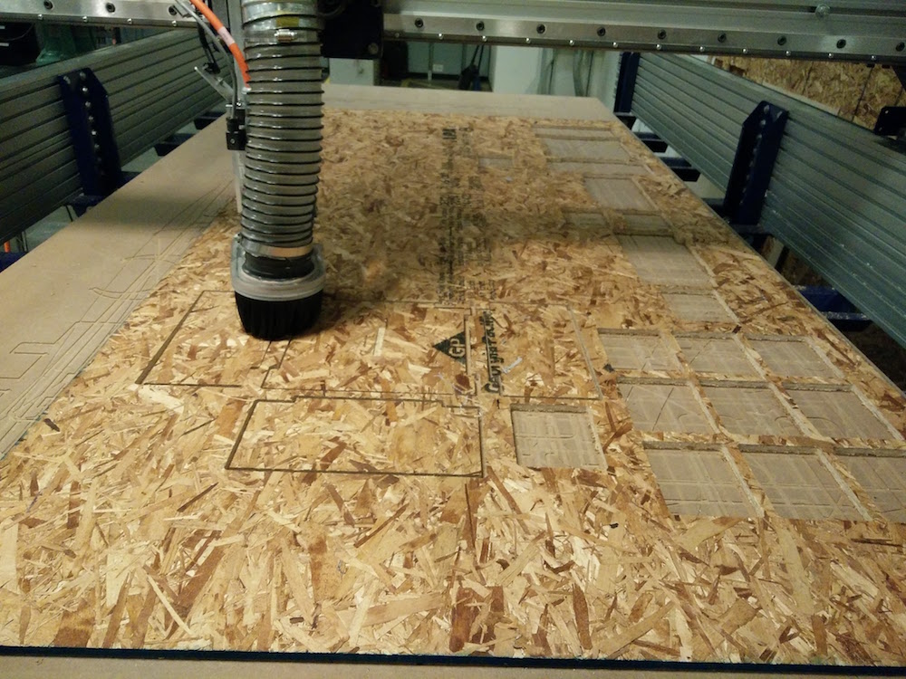
For the cutting, I used the 1/8" mill head. I used nails to nail the board to the sacrificial layer. I set the cutting depth to 5.3" and the raster etching depth to 2.5". I then zeroed the x&y axes normally, while using the aluminium plate to zero the z axis. The cutting took around 45 minutes to complete.
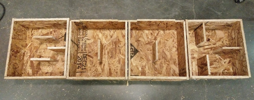
At first everything went smooth, but then in between the machine started sucking in my small parts, because the vacuum was too good. The possible workarounds were to a. create a joint, or b. keep pauding and pulling out small pieces. I chose the latter.
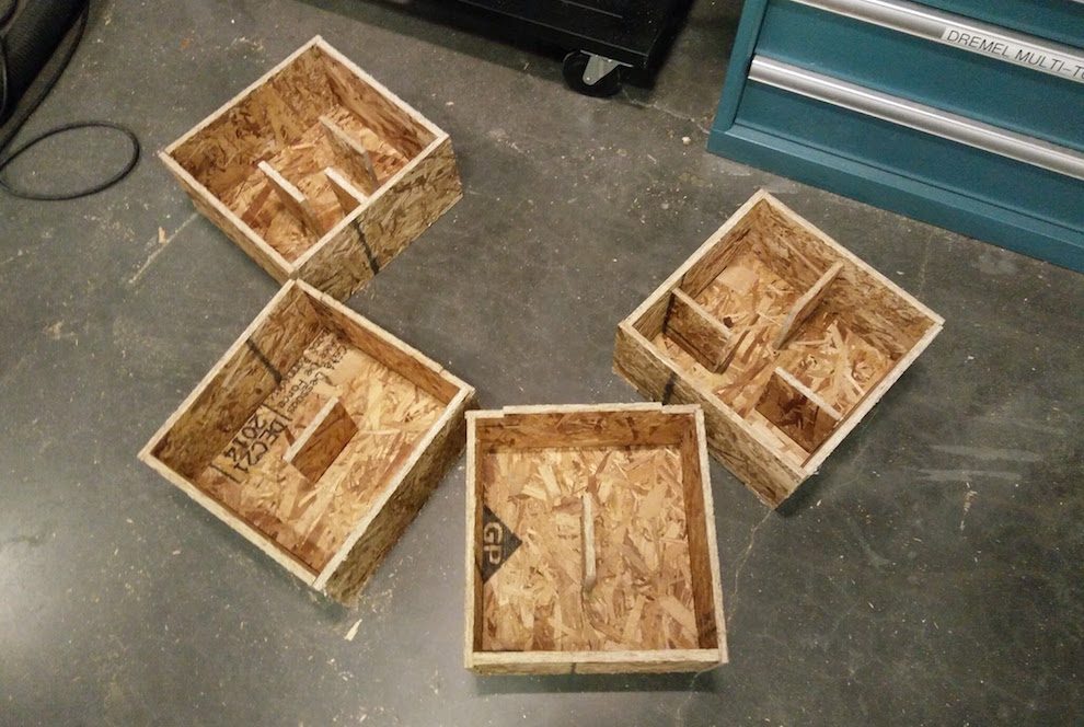
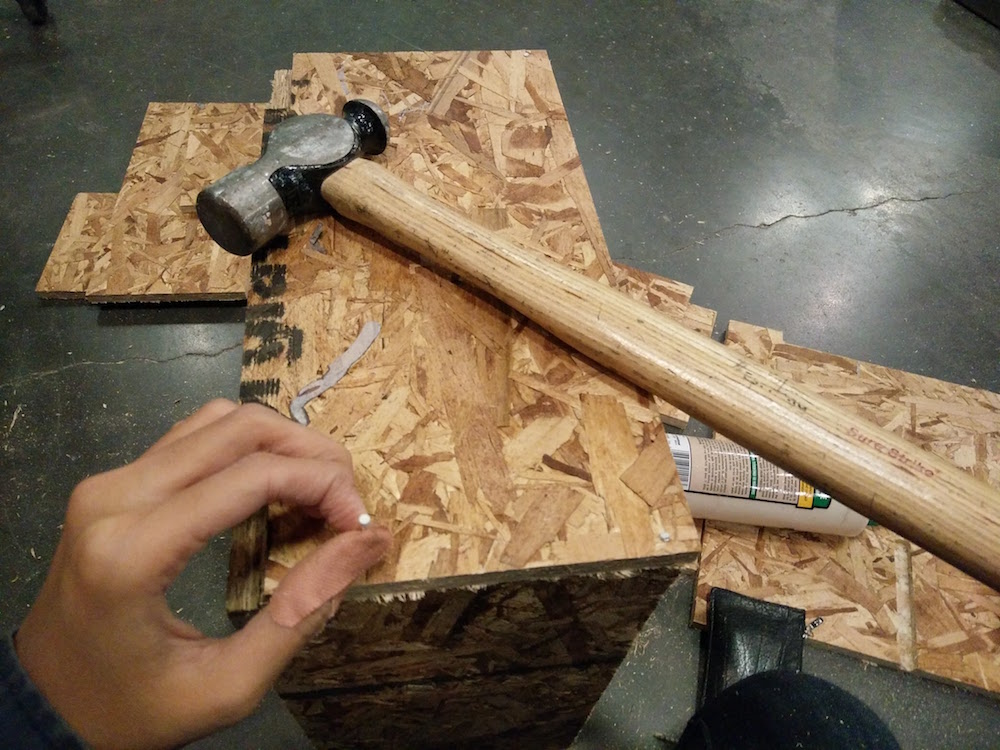
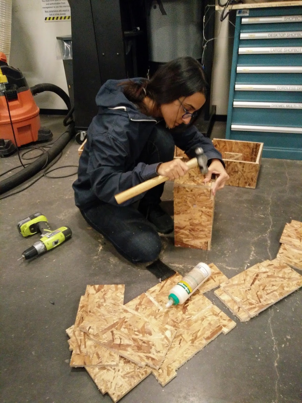
The shelf modules came out nice, however, I made some errors in the press fit dimensions. So the joints were slightly lose, and I had to use nails to do it well. Nailing was harder than I thought. I kept inserting them at angles instead of perpendicular to the wood.
Embedded Programming
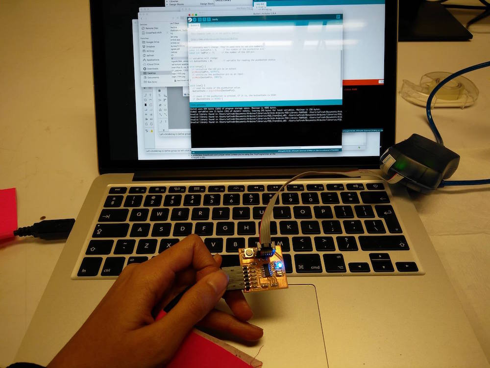
This week's assignment was to use various programming languages to program the board we built in week 5. I tried the Arduino IDE & C in Eclipse to be able to program my board to light up 3 LEDs on my board. Below is a string of failures and a tiny success.
Code in Arduino to make the 3 LEDs blink (2 after button, and 1 with fade)
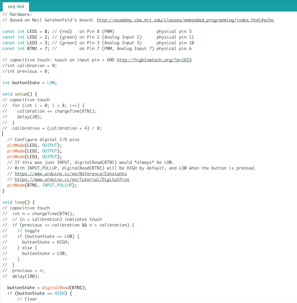
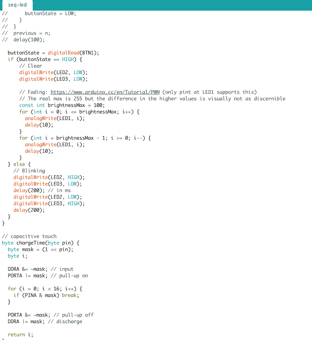
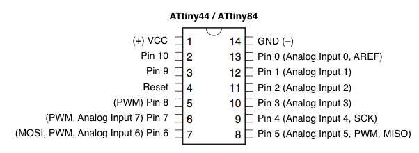
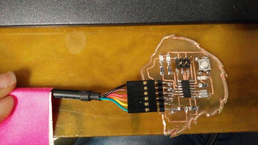
I started with the board I made last week, and it wouldn't get power appropriately (orange light on programmer), so I decided that since the vinyl cut traces were so delicate, I might as well mill another board.
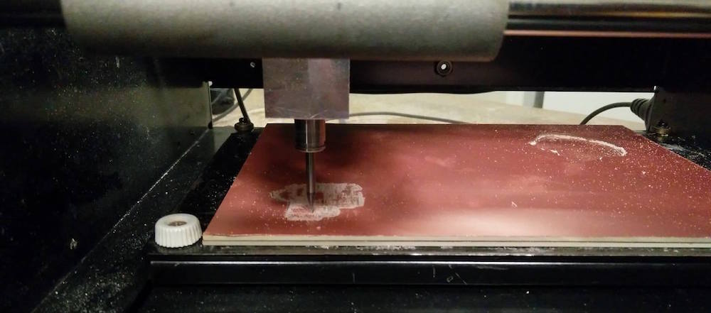
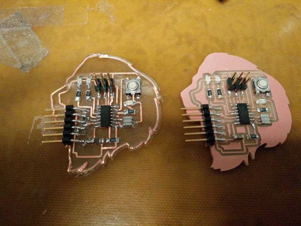
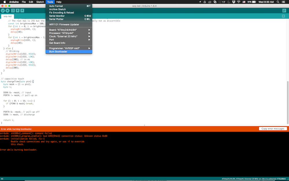
So here I have the new board. I first tried to use Arduino IDE to be able to burn the bootloader after downloading the attiny dependencies in Arduino. It was pretty straitforward.
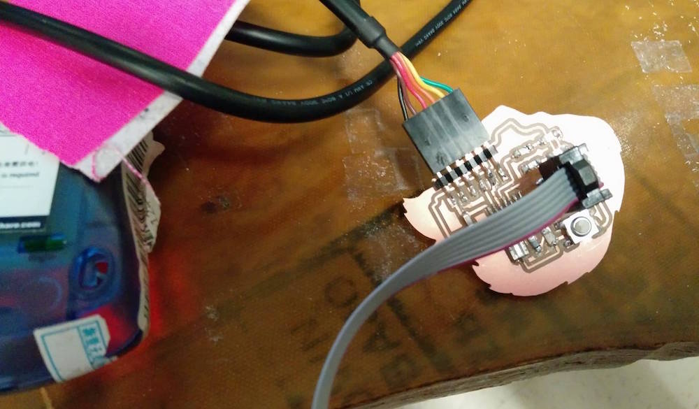

I would constantly get the following error :
avrdude: stk500v2_command(): command failed
avrdude: stk500v2_program_enable(): bad AVRISPmkII connection status: Unknown status 0x00
avrdude: initialization failed, rc=-1
Double check connections and try again, or use -F to override this check.
Error while burning bootloader.
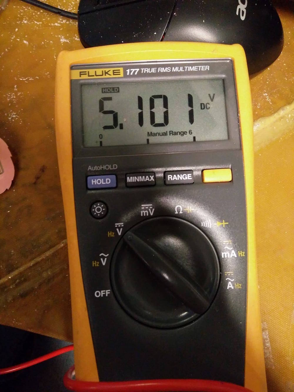
I checked all the voltages using the multimeter and verfiied that everything that needed to be connected was connected. I then asked the TA, and he mentioned that I had not cleaned the dust off my board properly, and it would be useful to make another board with only the main components (Attiny, headers, capacitor, resistor, clock), and check if the computer recognizes it. He also asked me to verify if the computer recognizes this board, using the command
sudo avrdude -c avrisp2 -p t44
I would get this error in my terminal :
avrdude: stk500v2_command(): command failed
avrdude: stk500v2_program_enable(): bad AVRISPmkII connection status: Unknown status 0x00
avrdude: initialization failed, rc=-1
Double check connections and try again, or use -F to override this check.
I tried to force run it with '-F' , and failed as well.
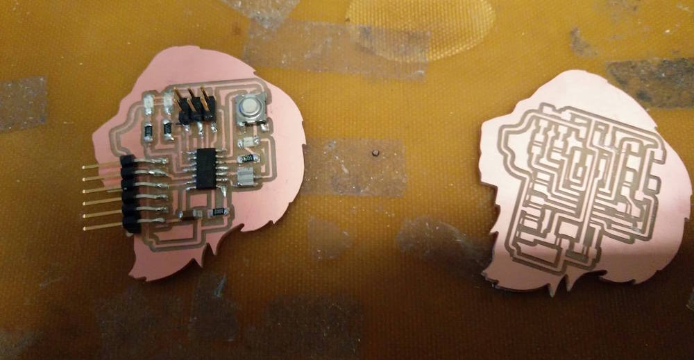
So I printed the new board with only the essentials and tried to test if the computer recognizes it, I got the same error. This time I had verified the circuit with the TA, reprinted it, cleaned the board well, and soldered only the essentials.
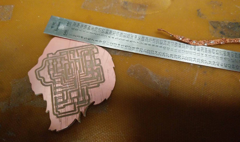
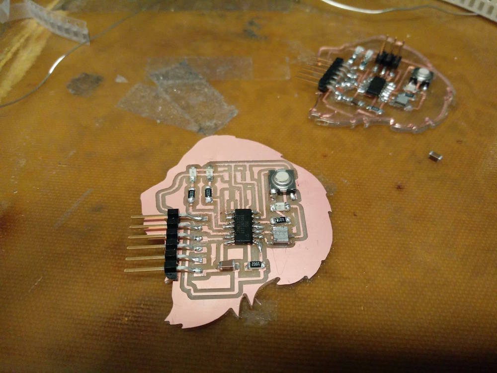
I got the same error. I asked the TA and my colleages (Anna, Tomas) for help, and we could all collectively not figure out what was going on, because the potential differences seemed very accurate.
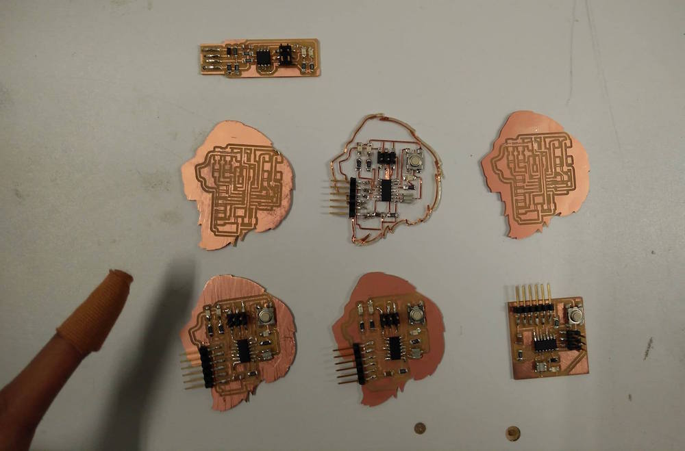
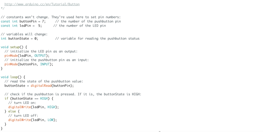
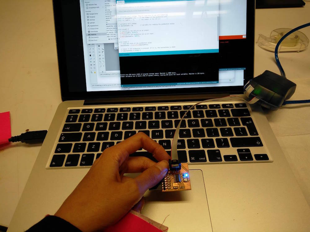
6 boards and 1 soldered finger later, I shifted to using another board to be able to practice programming. I used Anna's board and the Arduino IDE to run the simple Button code. We only had to modify some pin numbers and it was good to go.
Molding and Casting

This was my favorite week since I got to try a bunch of molding and casting techniques + material and learn a lot by making/failing.
Drystone brain casitng attempt 1
For molding and casting week, I first wanted to make a 3D model of my friend's brain, and embed it in a transparent skull. My friend (from Brain & CogSci) had data from their fMRI scan in the NIFTI (.nii) format, which basically looked like a bunch of numbers. I used this tutorial to convert it to a .stl file using meshlab. It was fairly straightforward. I used the modeling features to deepen some of the crevices of brain matter to make them more prominent for milling. I also made the models solid and filled in some empty parts on the bottom by approximation.
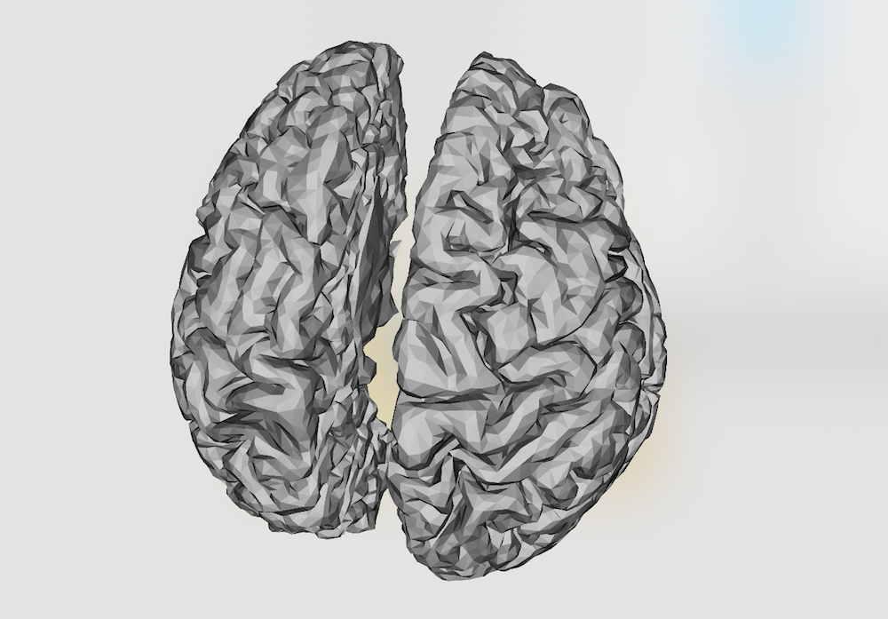
After having the atl file, I was ready to mill it. I followed the recommended settings by Tom and used the 1/8" tool. I made a combined roughing and finishing tool path.
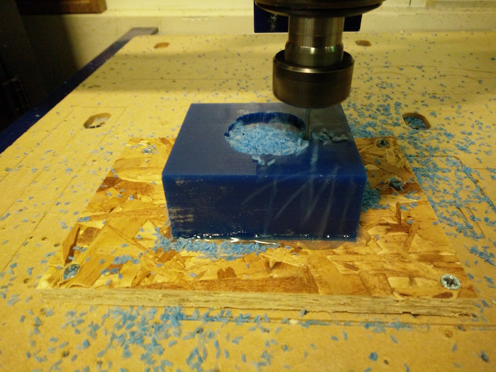
Note that the bottom of the brain will not mill properly because it is a subtractive process. There is no milling workaround, unless you make a 2 part mold.
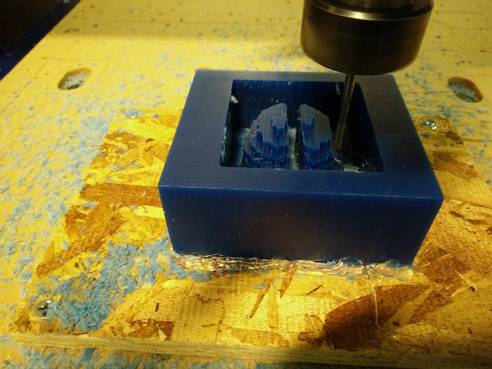
One of the mistakes that I made that I did not pull out the tool enough to go till the depth of the brain bottom. This ended up damaging the top of the wax piece. It was alright in this case since wax is a soft material, but this can potentially harm the machine if the material being milled was not wax.
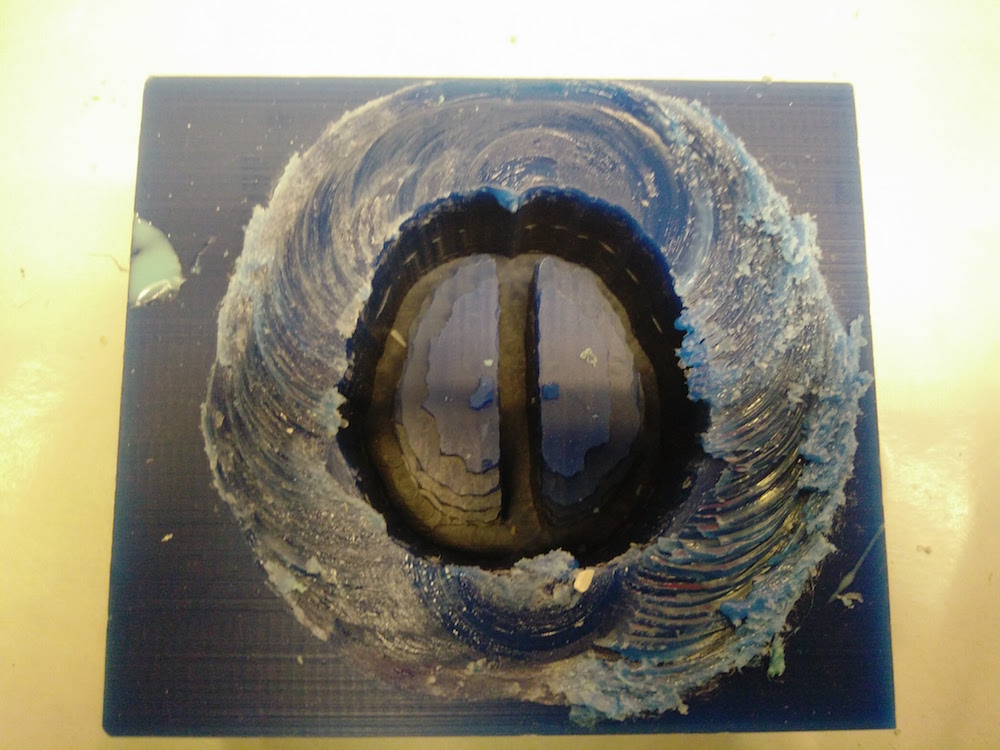
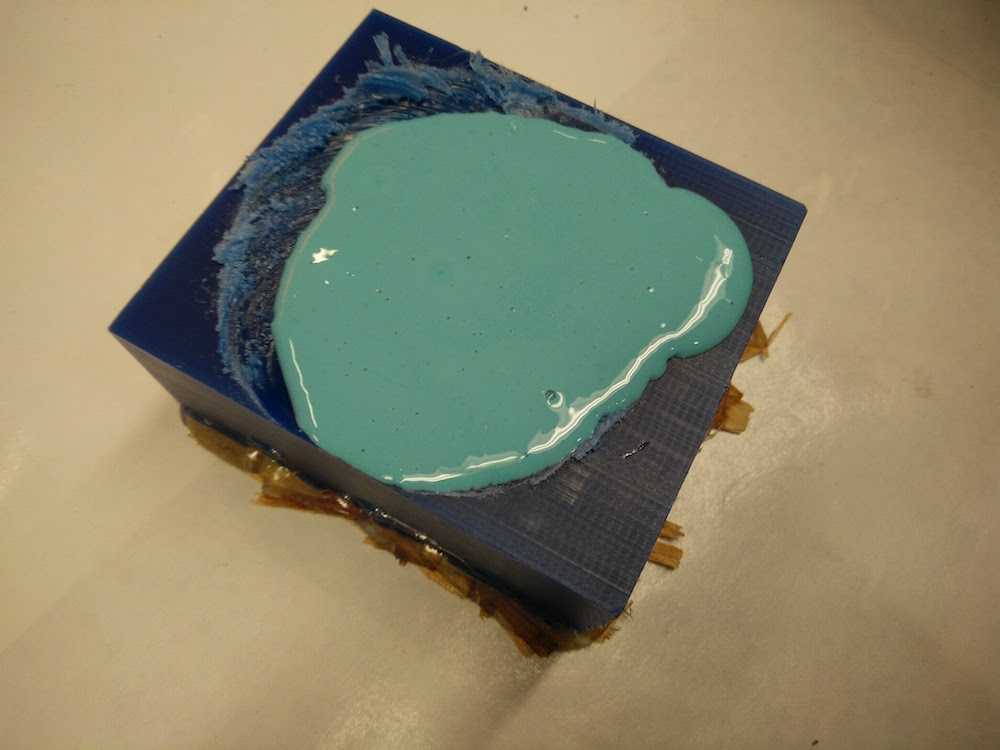
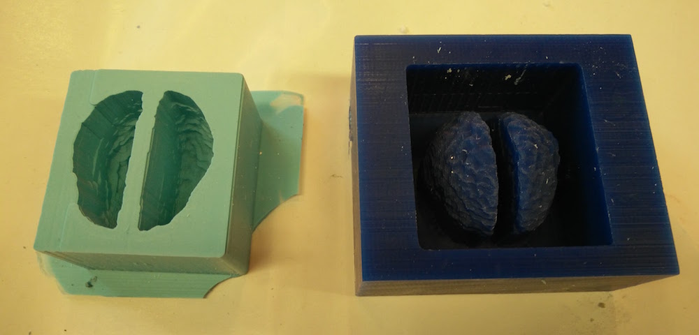
I used oomoo to make the mold. I followed the instructions on the box to mix the oomoo parts in 1:1 ratio and let it set over night.
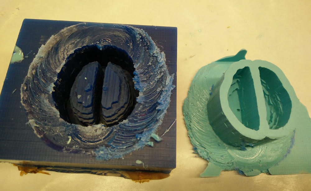
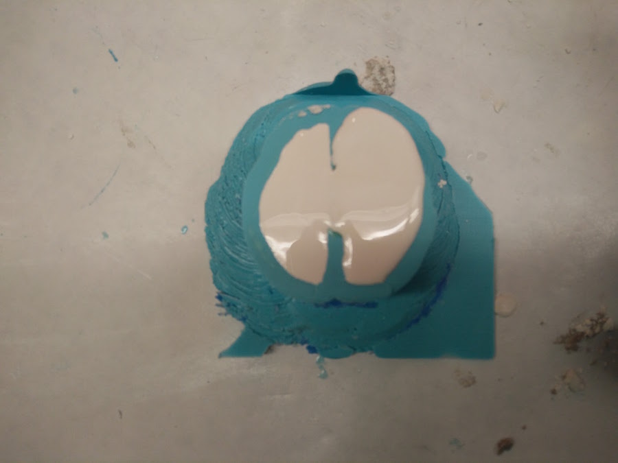
I used drystone for casting the final mode. I forgot to put the oil spray layer for easy removal, but removal was still fairly simple.
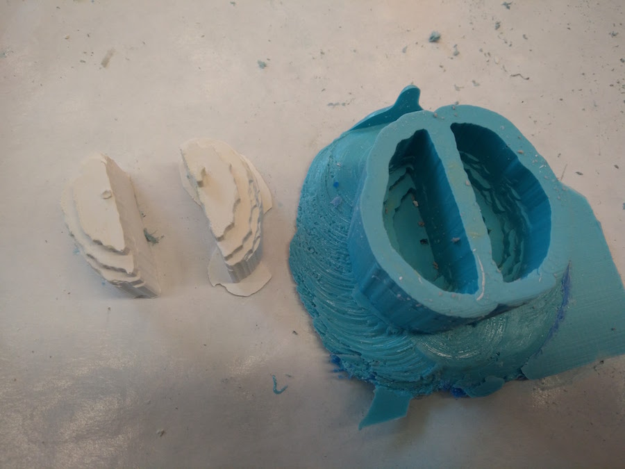
Also, the model came out looking very very rough compares to the 3D model. I was confused about this and asked Tom for help. He asked me to redo it with separate tool paths for roughing and finishing.
Drystone brain casitng attempt 2
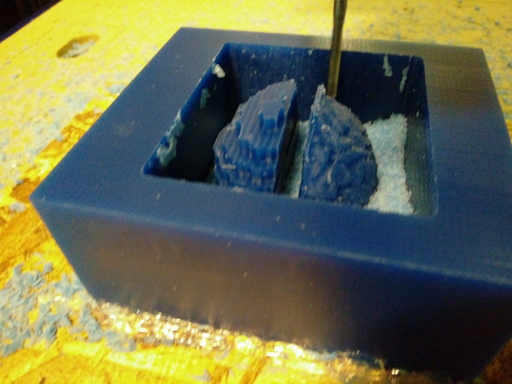
The second model came out looking super neat with good finishing. So I believe either I messed up with a setting in the first attempt, or separating the tool paths was the trick.
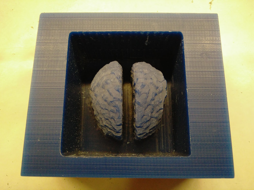
However, an interesting thing that happened was that the machine froze at 96% of the finishing tool path. I lost the zeros, but since I had zeroed fairly precisely, I zeroed again and ran it again, and it again froze at 96%. I just till the remaining details manually, but we were intrigued by this problem. At first we thought it was something with the model because my classmate could mill their model completely. However, Tom ran the cut on the other (big) Shopbot milling machine, in the air with no material, and it completed. So, he diagnosed that it is a problem with the Desktop Shopbot milling machine (small) and that he would look into it.
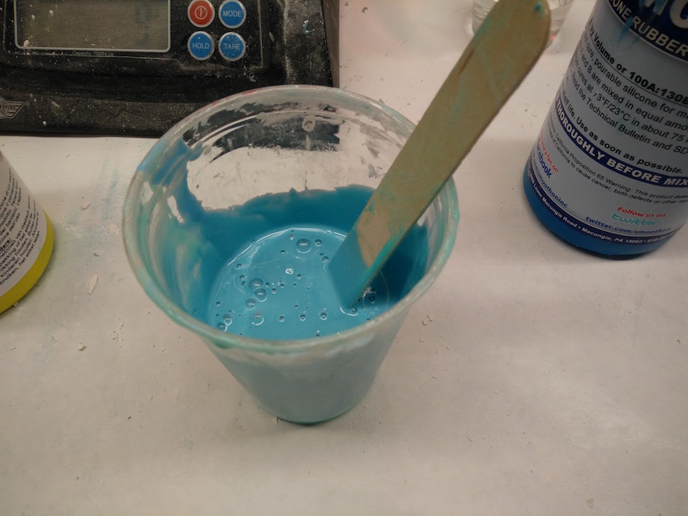
I followed the same oomoo, drystone drill.
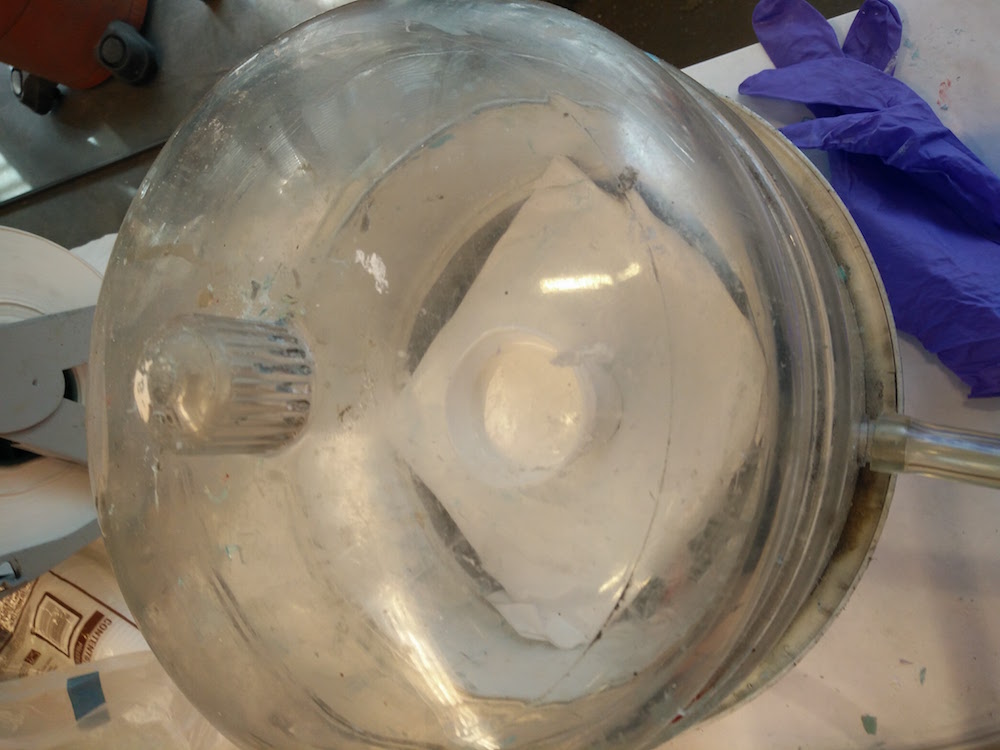
I made sure I used the cool vacuum machine to de-bubble the oomoo as well as the drystone mixture.
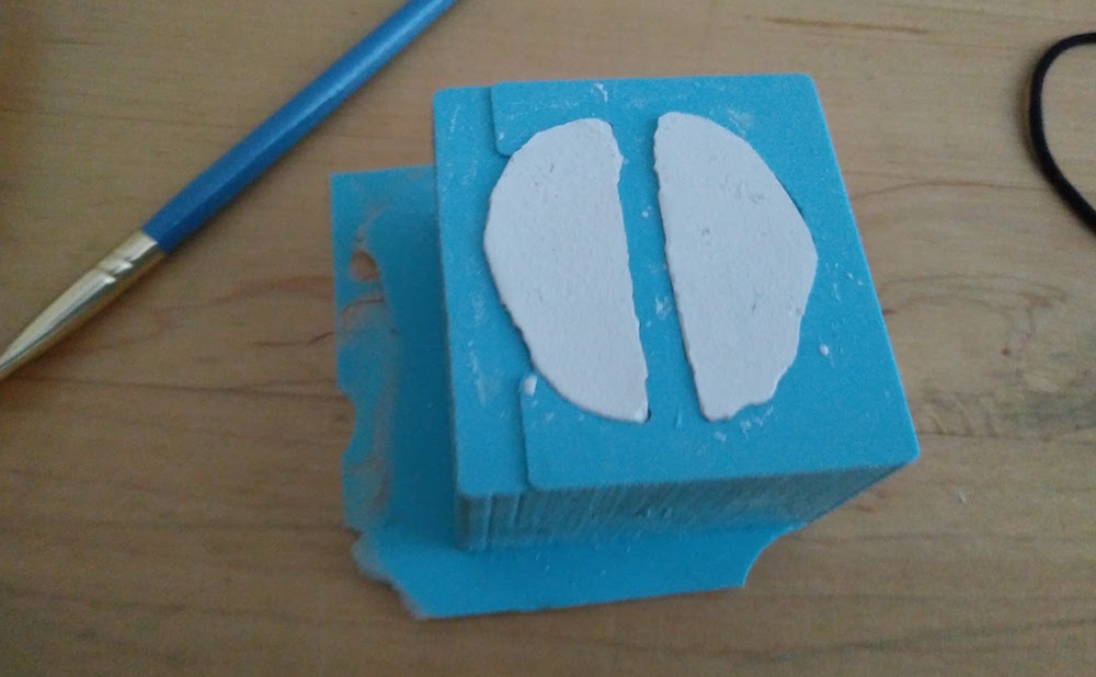
I used the sandpaper machine to smoothen the bottoms of the final mold.
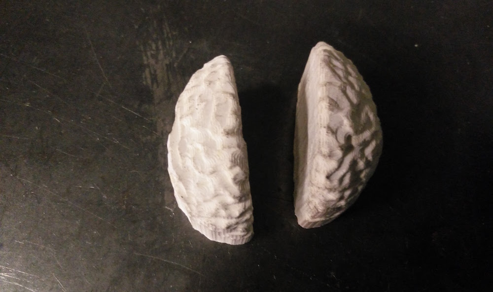
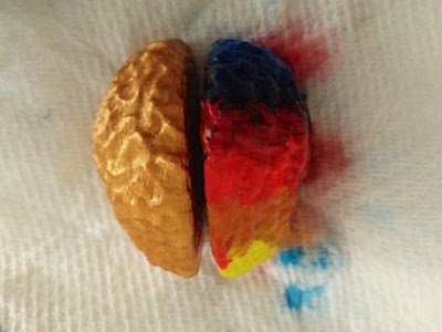
Since this was a left brain, right brain cast, I went ahead and painted them as left and right brain. Also, my final aim was to embed these into a skull, so I wanted them to be nice and bright.
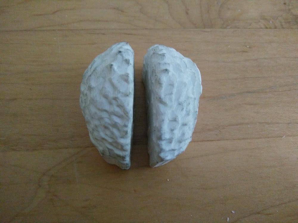
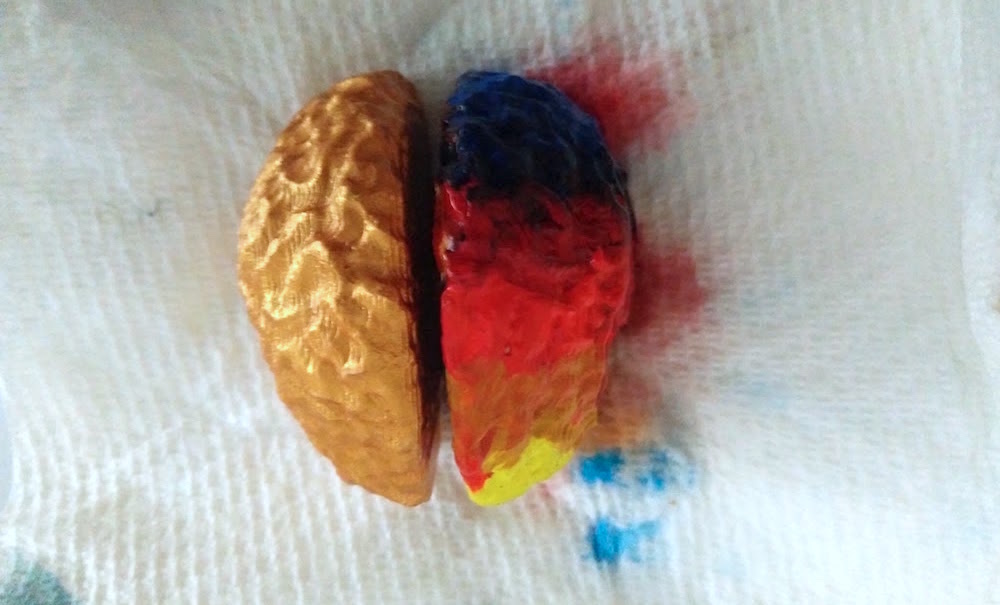
Skull embedded with the brain
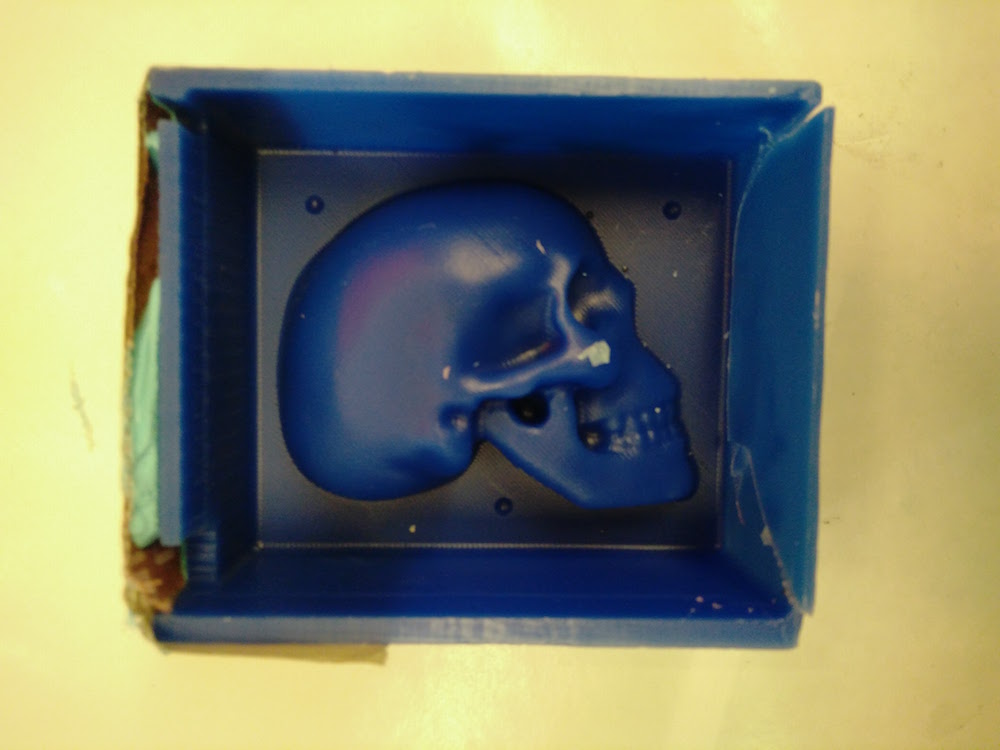
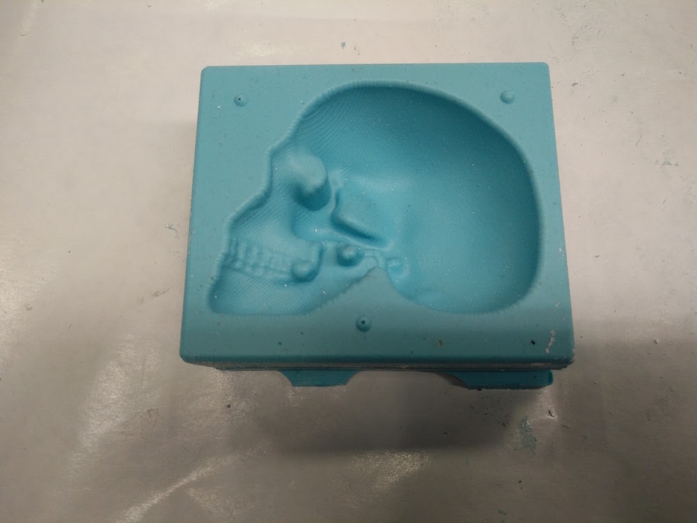
The skull model I was using is a Thingiverse model and not designed by me. I used this model's positive in was, and used Ooomoo to make the mold. The process was exactly the same as the brain.
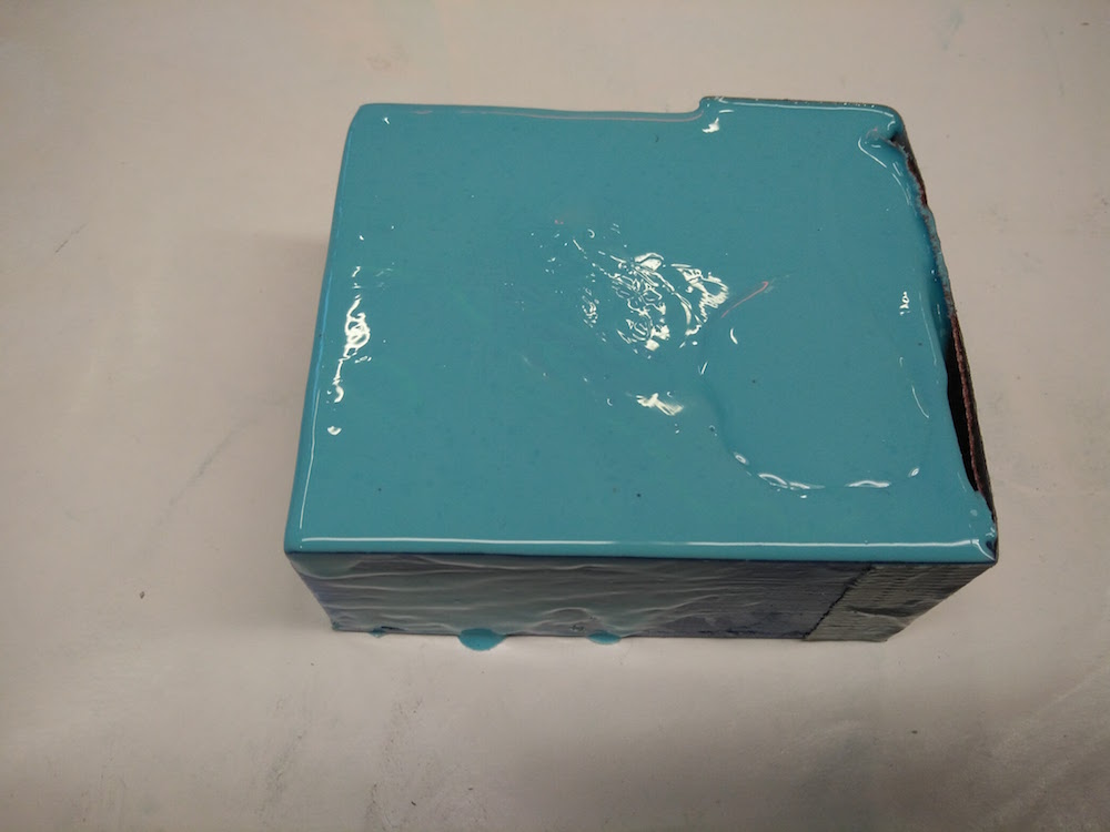
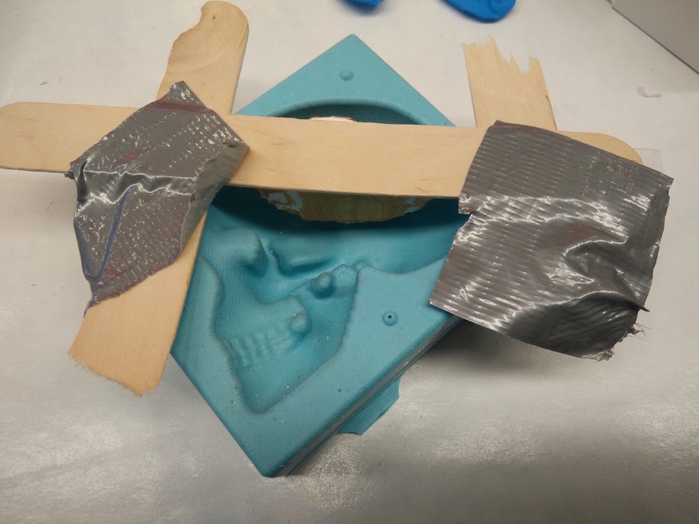
I then used two ice cream sticks, and tape to suspend the golden painted brain model in air within the skull. This was a bad idea and we find out later why.
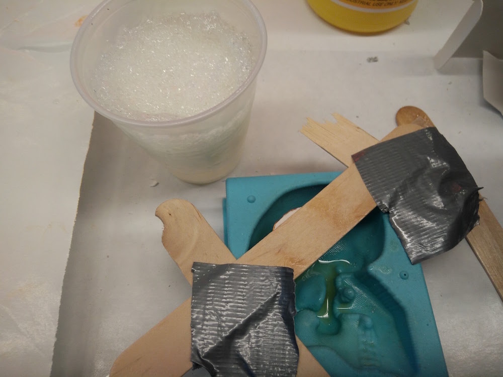
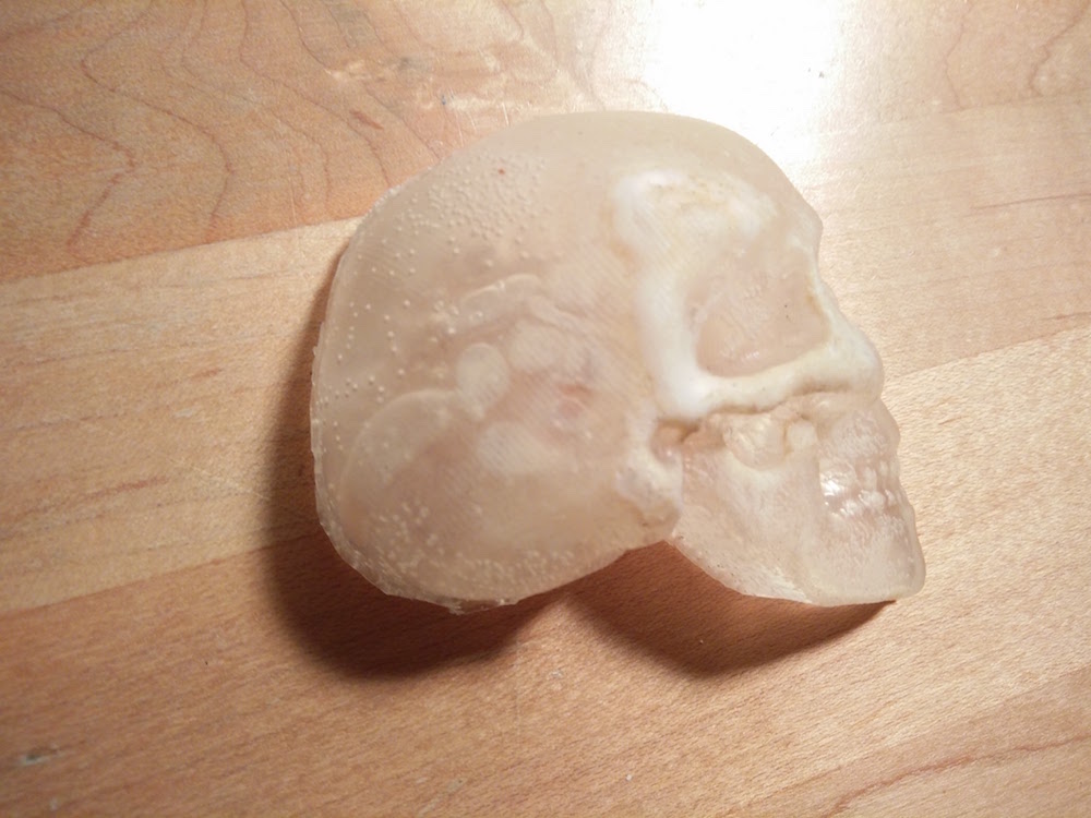
I used the non stick spray to be able to remove it well. I used the The Smooth-Cast™ 325 ColorMatch™ that Ryan from the ACT group gave me (thanks Ryan). It's not exactly transparent since it's made for adding color dyes to it, but that is what I found in the lab. The first time I ade the mixture, it had many bubbles. So I spent a lot of time de-bubbling it. As I took it out of the vacuum machine, it had already frozen, and the cup was very hot. I then realized that this mixture takes 5 minutes to settle. So then I made another mixture and did a quick de-bubble after which I poured it in the skull with the suspended brain. Halloween done right.
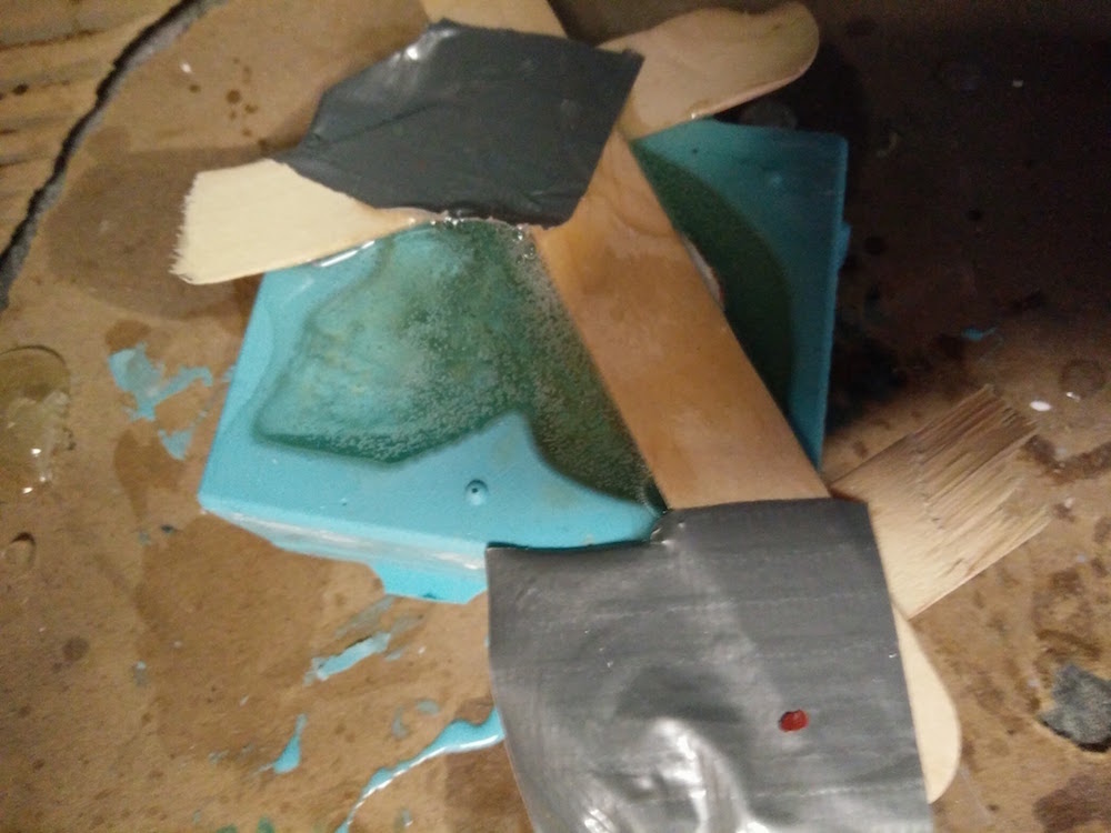
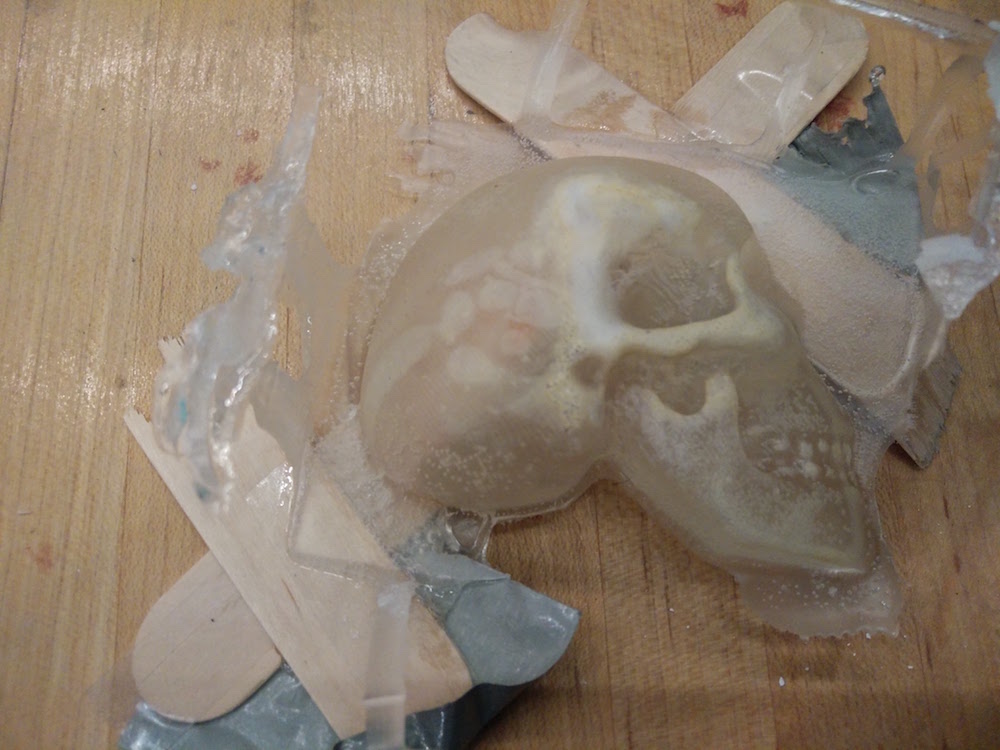
After drying (1 hour), the model poppedout very easily. It was extremely difficult trying to remove the ice cream sticks because they had stuck so well with the cast. Also the non stick spray had sedimented in an ugly color on the surface. Also, the material was very translucent and not transparent as I had hoped. I later learned that I should have used the clear Epoxy resin material to get a transparent look. The brain is slightly visible through the skull, but not completely.
Chocolate skulls and brains
While hanging out in the workshop I met Anna and Pinar and they had extra food safe molding material and were planning on making chocolates. I got excited and joined that venture, because chocolate!
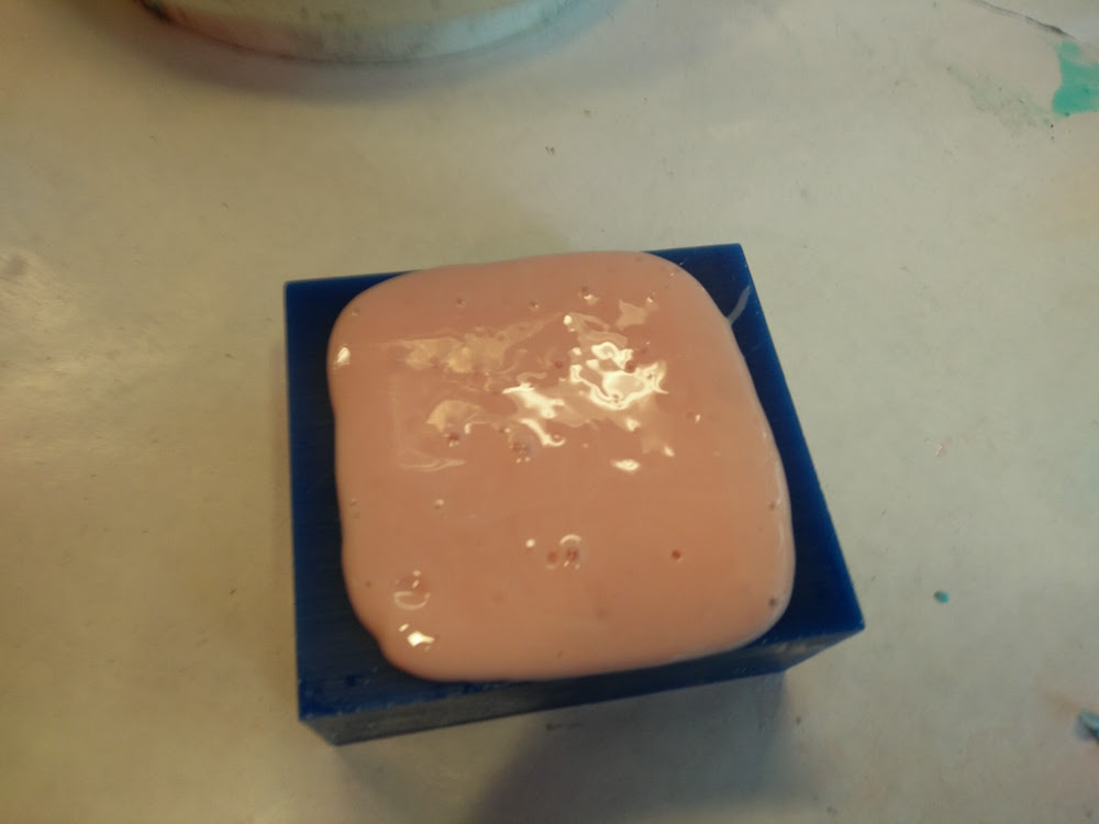
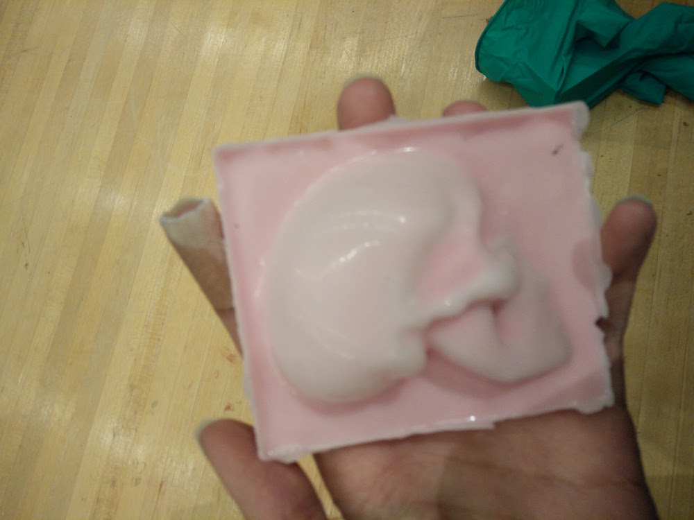
I used the food friendly mold material to make molds of the brain and the skull.
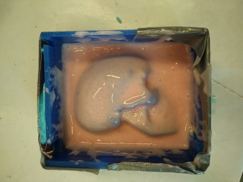
Since we were short of material and I was doing this part for fun, I wanted to experiment if I could just do a thin layer instead of fill in my block with mold mixture and get away with it. And it worked well! In fact the mold it gave out was better than the full-fill molds we have, but I believe it isn't as robust and can't be used multiple times.
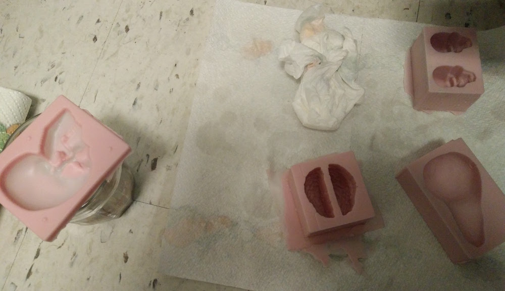
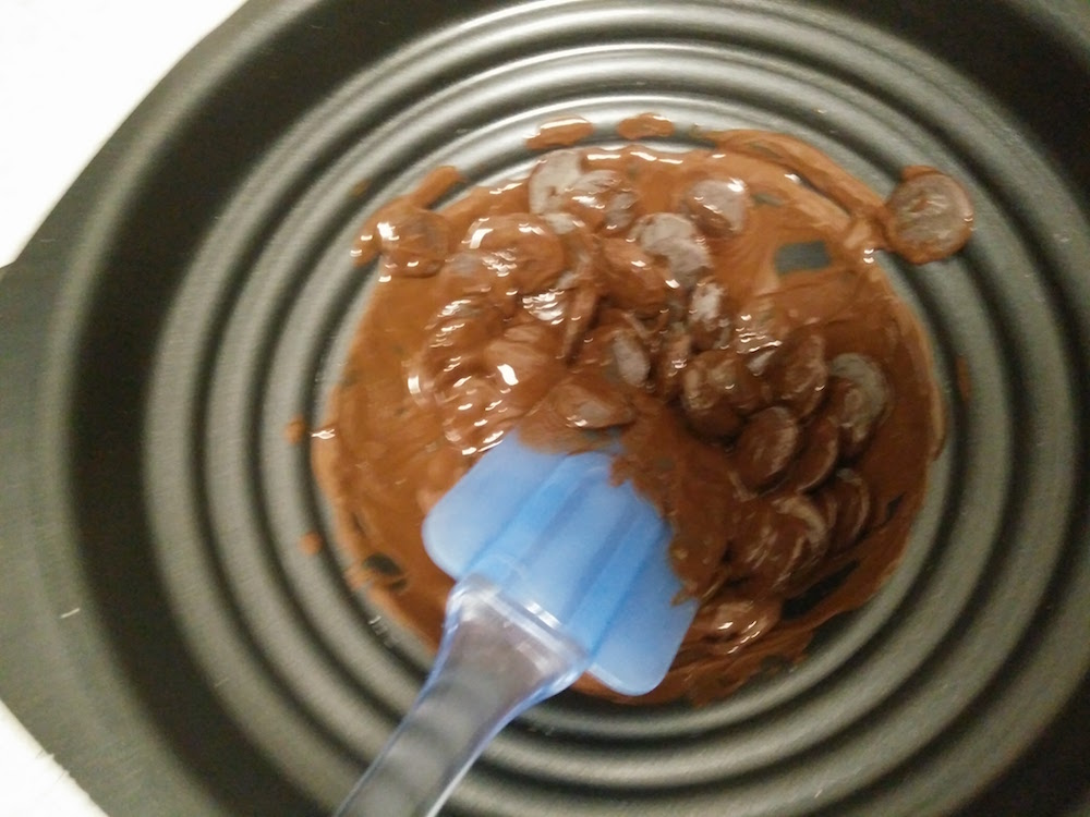
We used chocolate pellets that Anna had at the student center and used a double boiler to melt them. When it was a consistent mixture, we poured them into our molds.
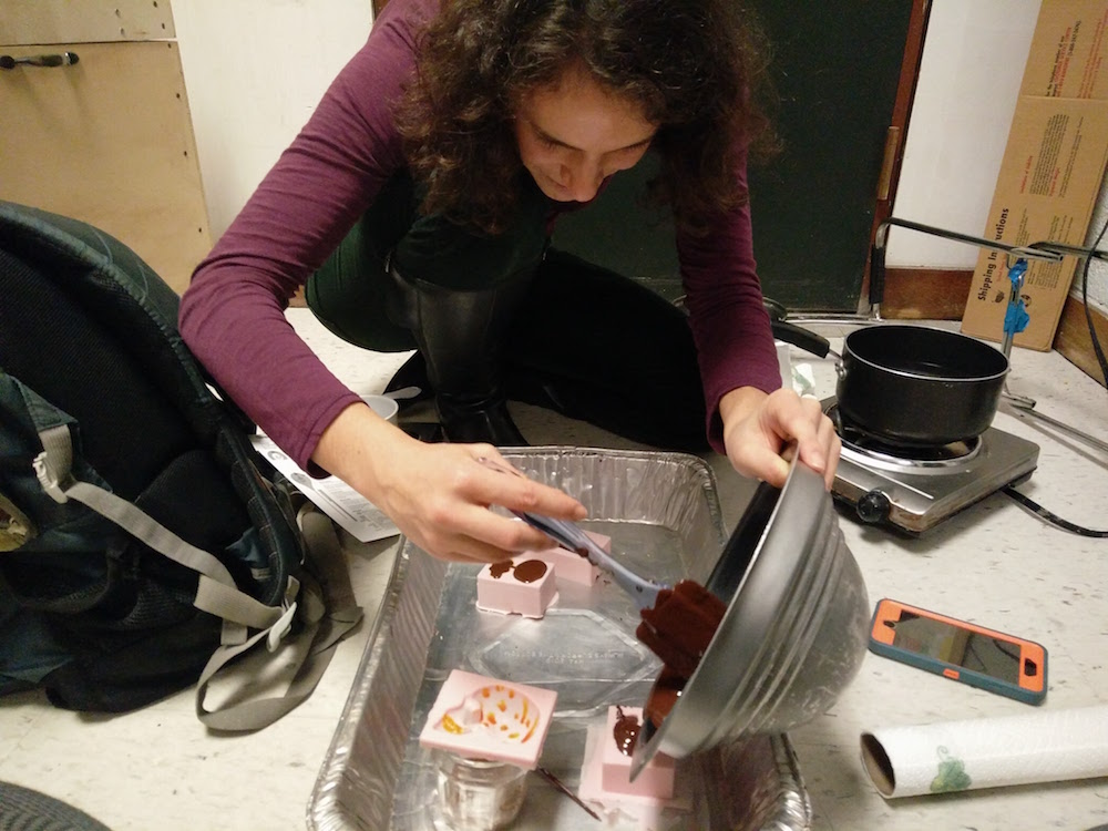
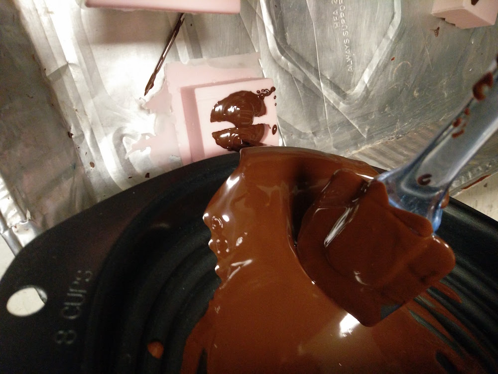
We also used some colored coco butter to paint the insides of the mold to get painted chocolate.
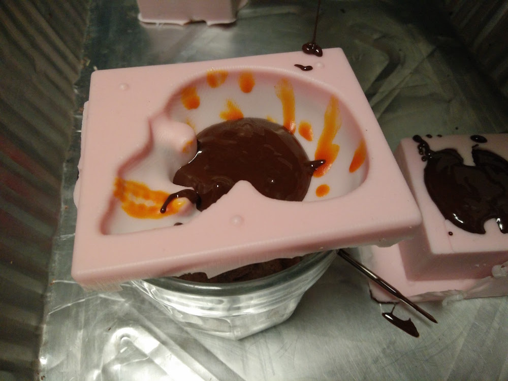
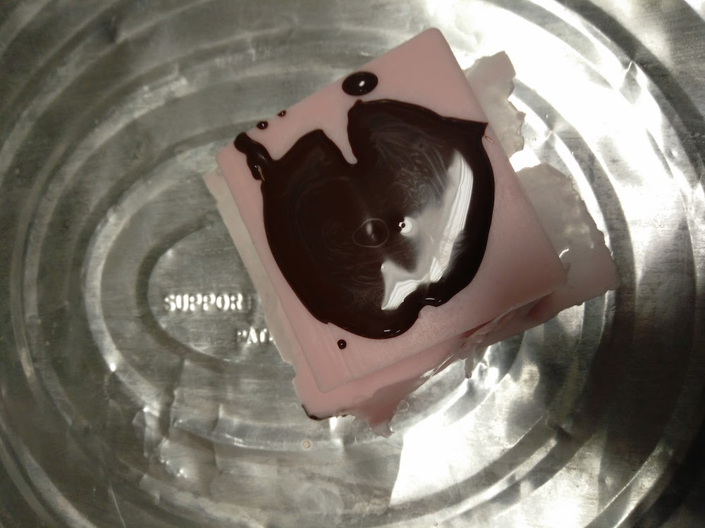
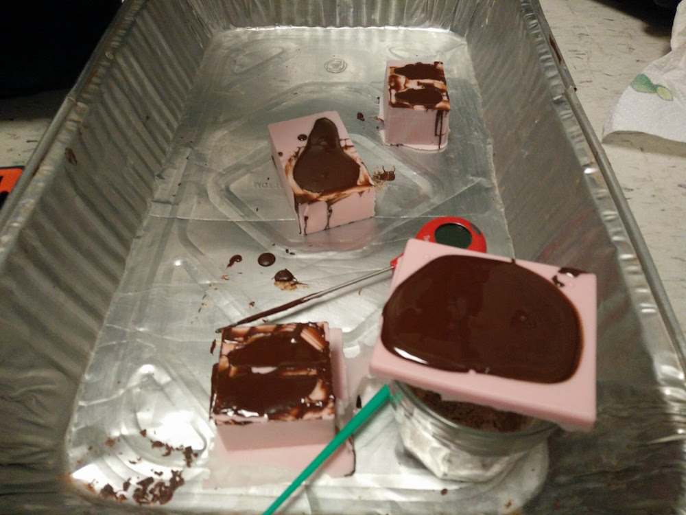
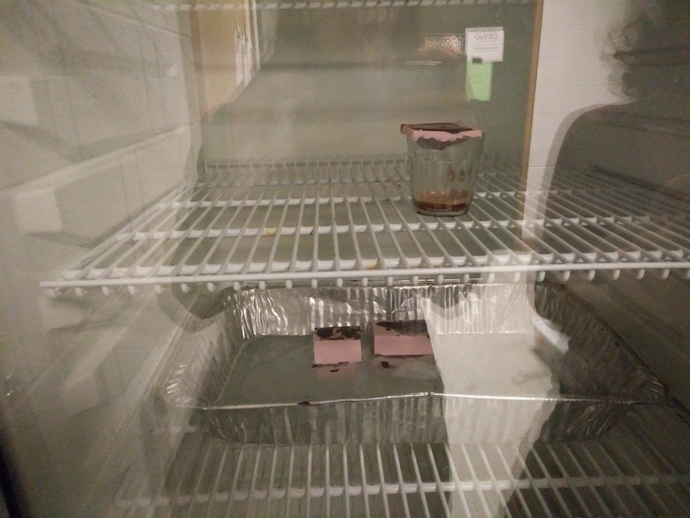
We put the chocolate casts in the fridge for quick setting. Since the skull mold was so thin, we used a cup to balance it on.
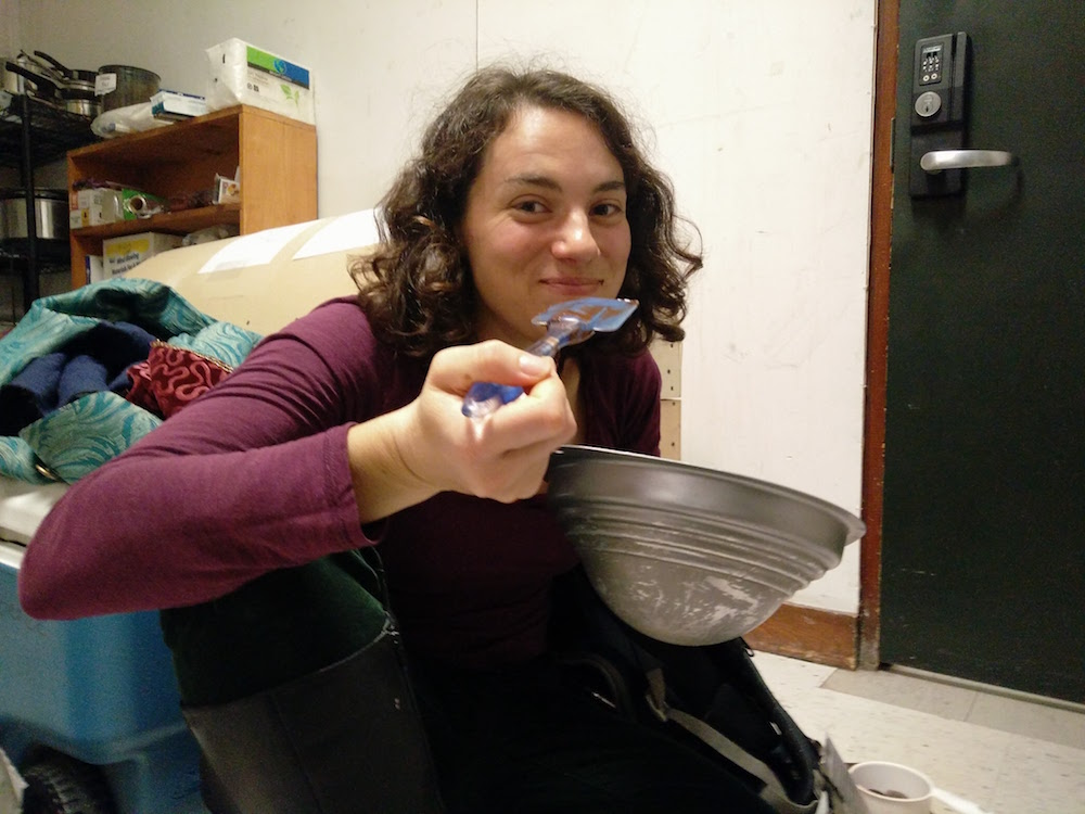
This process was especially fun because it involved eating a lot of chocolate.
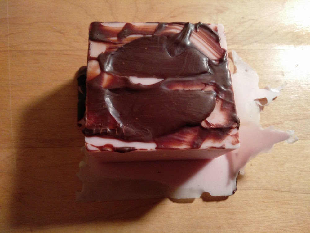
It would be cool to try this with different chocolates and the suspension idea. I could make the skull in white chocolate, and suspend the brain in it, which is made with brown chocolate. I can still make it since I have the molds.
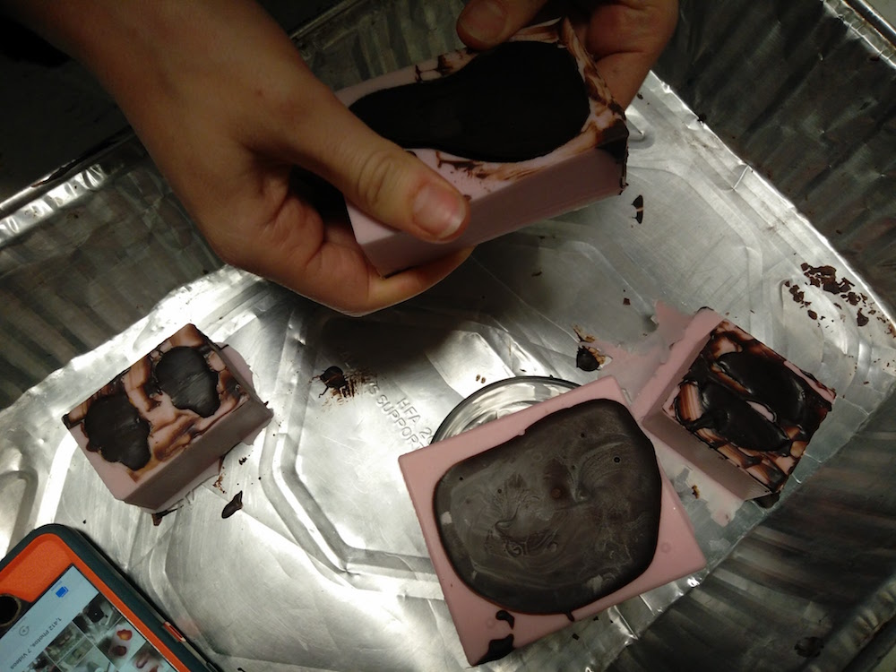
The chocolate molds tool >30 min to settle in the fridge and easily popped out. The thin film of the skull was especially easy to work with while popping it out.
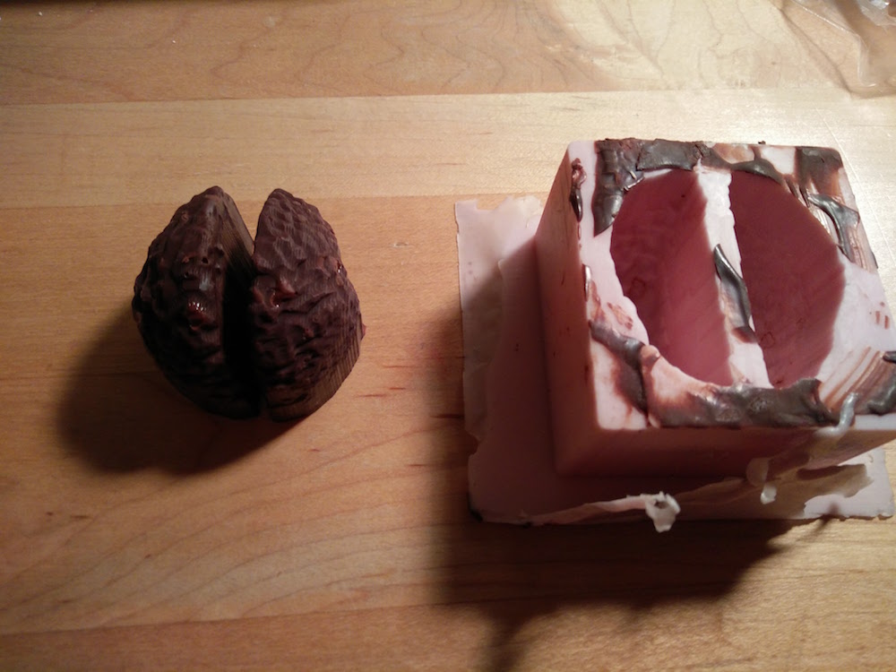
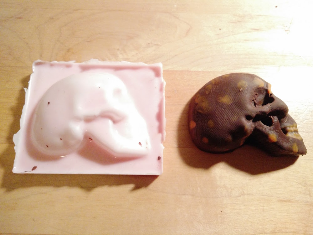
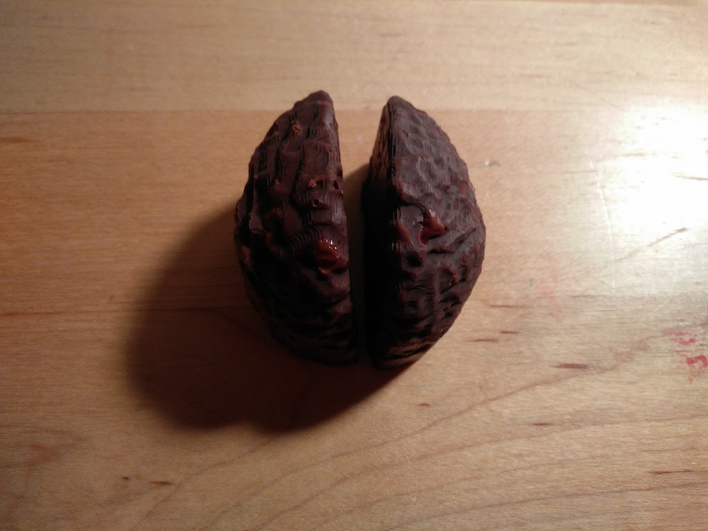
Face masks
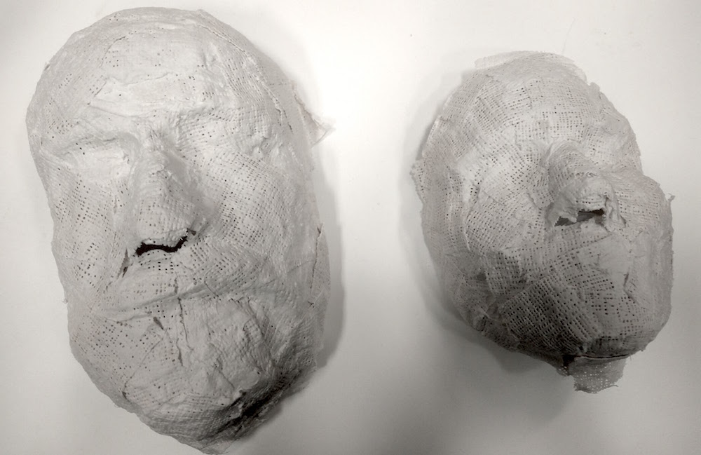
I also wanted to use this week to make some plastic masks of real people. I wanted a thin film mask and brainstormed with multiple people about how to do it. We settled on the idea of making 2 separate molds (positive and negative) of faces, and pouring plastic in between them. But first I needed an accurate skin impression, so I headed to Reynold & Blick's to try to get skin friendly casting material. I bought some gauze strips, and skin friendly plaster to do this.
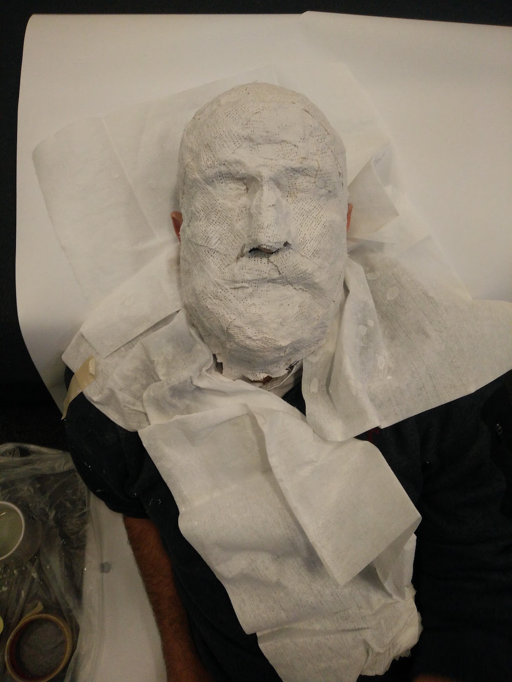
Super grateful to Anastasia and Pedro for volunteering and sitting so patiently through this. I cut the gauce strips into smalled pieces, dipped them in the warm water + skin friendly plaster material, and applied them to the face. I did 3 layers. I left eh nostril portion open so that they are able to breath well. The process was fun. I used a hair dryer for quickening the drying process.
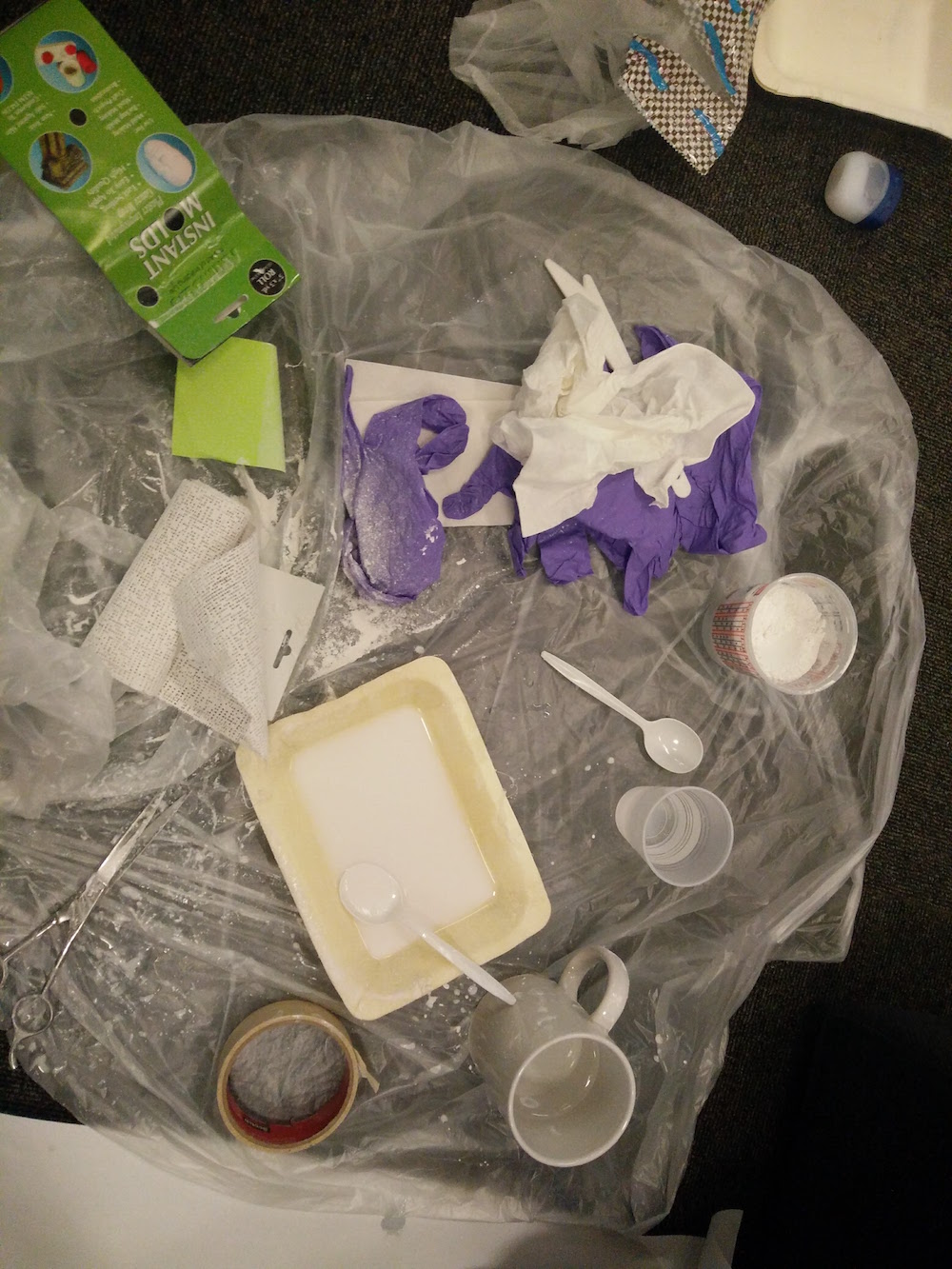
I started by applying a thick coast of vaseline on their face so that the mask comes off easily. Pedro's face was a challenge because he has beard and it was difficult to get the plaster stick to the beard.
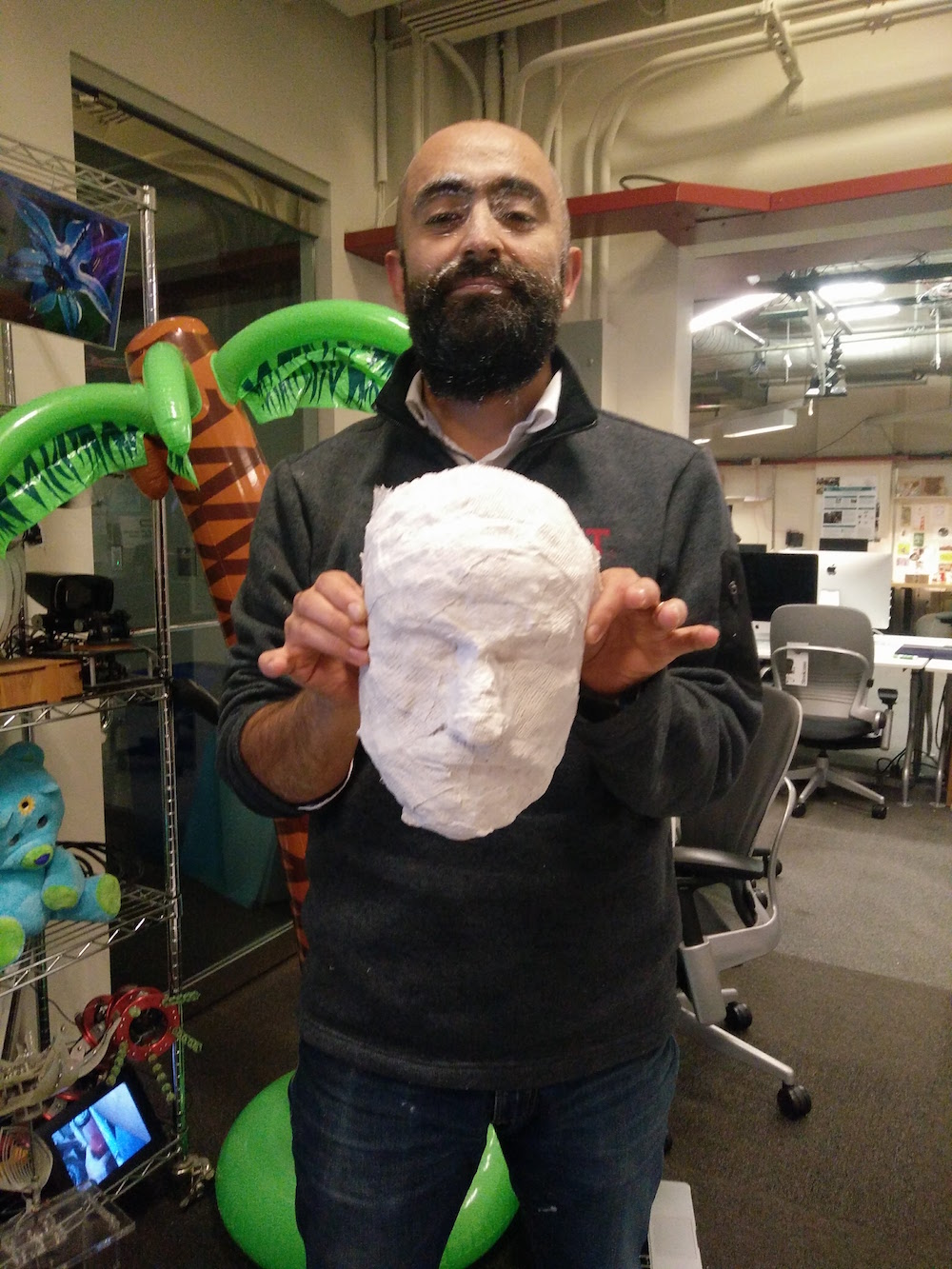
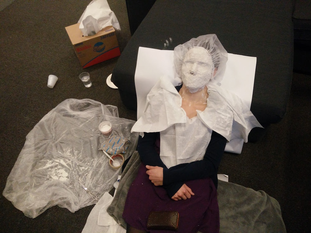
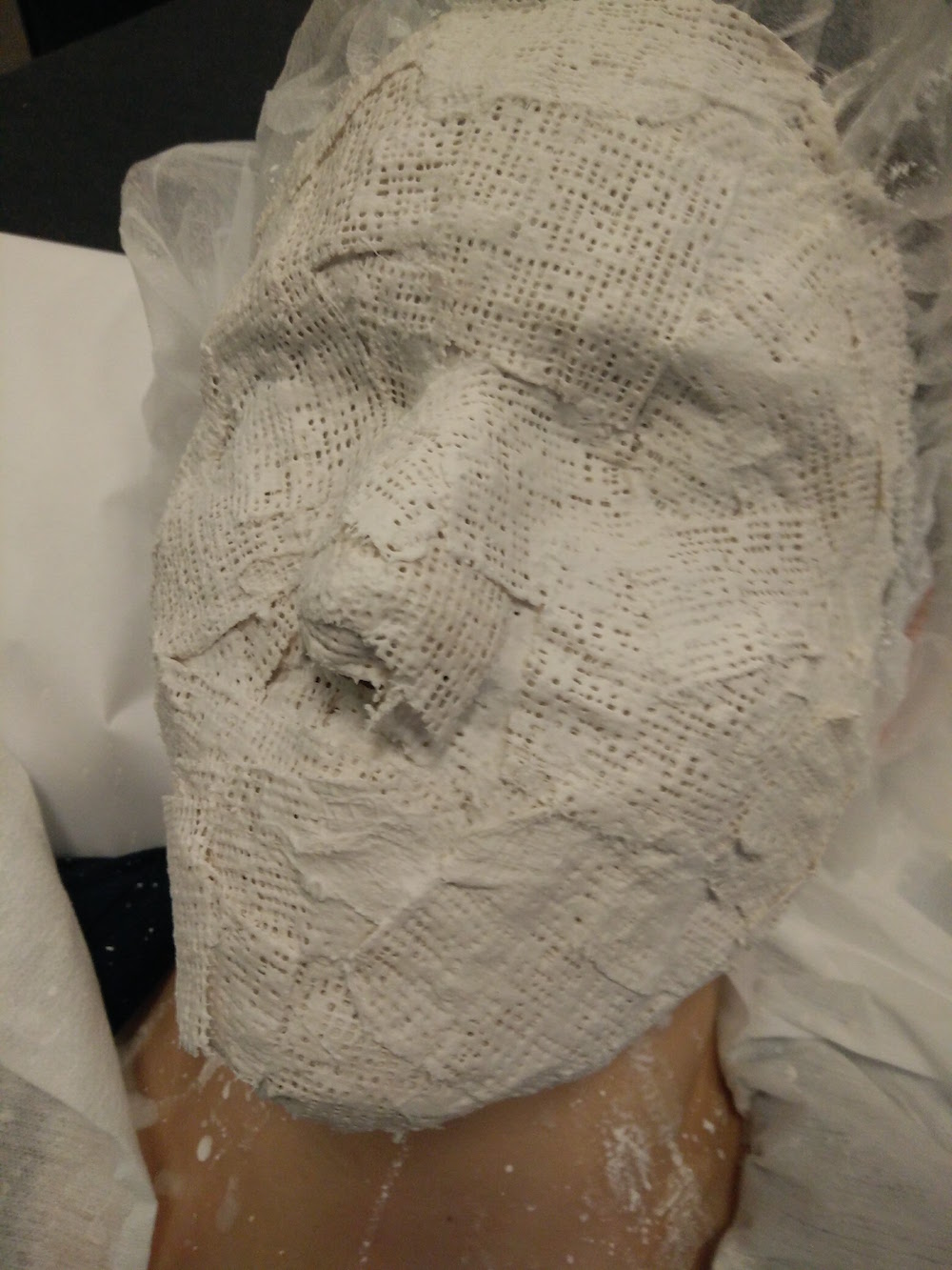
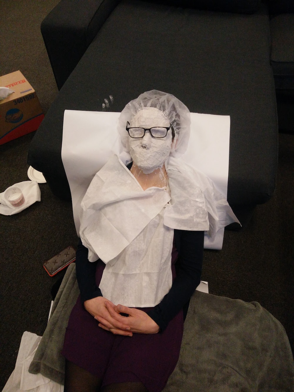
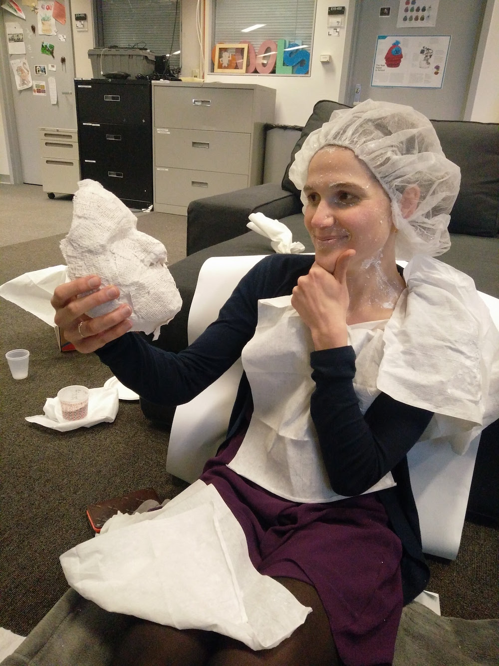
I now have face impressions of Anastasia and Pedro on the inner side of the plasters. I will now use clay to make a positive of the face model.
My next step is to make a positive and negative of the face impression using clay. I want to be able to make translucent plastic / silicon masks and then project different lights behind them to convey emotions.
Output Devices
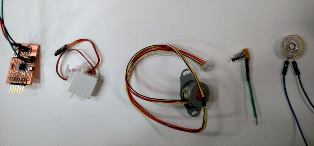
This week's assignment was to use the board I programmed in the Embedded Programming week to program an output device. I got pretty excited about trying my hands on a Servo motor, a Speaker, a mini-vibration motor, and a Stepper motor.
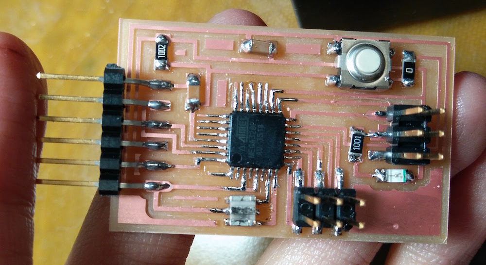
One of my remaining goals from the previous week was to make the hello.arduino.328p board using the Atmega 328p micro-controller. I milled the board using the 1/32" (outlines), 1/64" and 1/100" (traces). I used the 20MHz resonator as seen in the board linked in the Embedded programming week.
After soldering on components, I selected the correct board (Arduino nano in this case, since it uses the Atmega328p), I burnt the bootloader successfully. However, when I tried to upload programs to the board, it gave me the error -
avrdude: stk500_recv(): programmer is not responding
avrdude: stk500_getsync() attempt 1 of 10: not in sync: resp=0x00
 The mistake that I had made was that I did not add the 20MHz version of the board to the boards manager in Arduino. Neil guided me to add the boards using this. I wasn't sure if it was okay to burn bootloader again, so I just replaced the 20MHz resonator on my board with a 16 MHz resonator, and the board seemed to work (I checked it with programming the 13 pin LED).
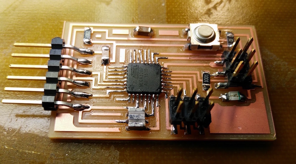
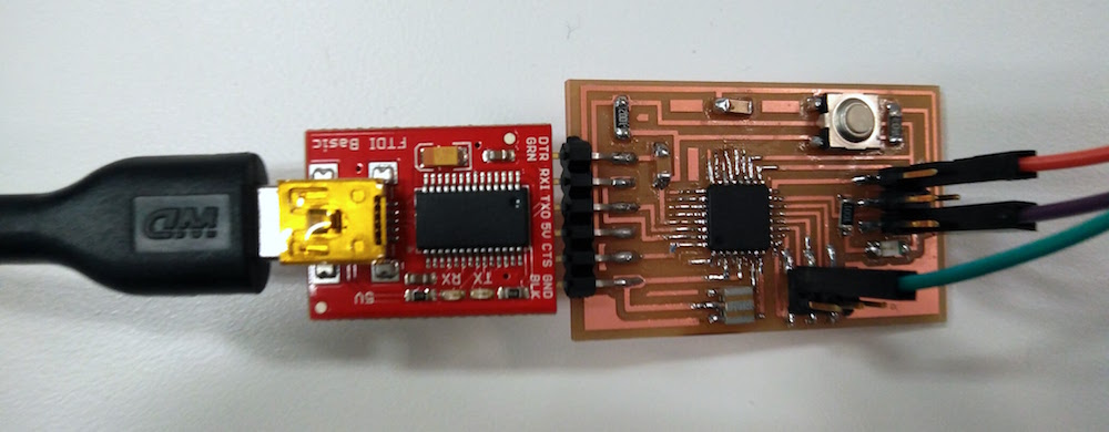
Since I had fabricated the FTDI pins on the board, but did not have an FTDI cable outside of the electronics lab, I used an IC BRIDGE USB-UART 5V MODULE to be able to a USB to program the board. I used the Atmega328p datasheet and arduino pinout map to be able to map the pins to arduino pins.
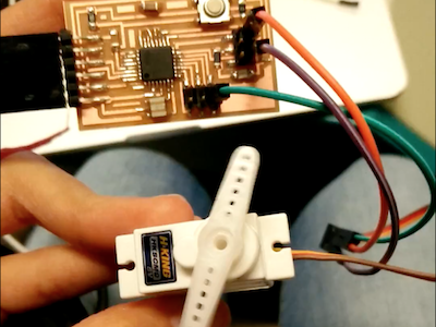
I first started to program the Servo motor, since I plan to use the servo motor with a potentiometer for my final project.
I then programmed the board to run tunes on a speaker. It was fairly straightforward. Only, you need to include the tone.h file to be able to use all standard tomes. I attached the speaker on digital pin 8.
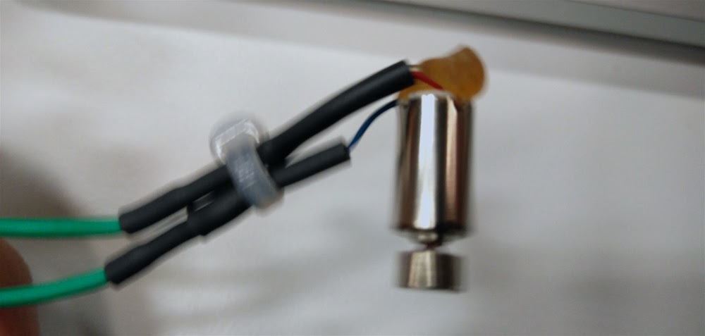
I then programmed the board to run a mini vibration motor with varying duty cycles. I found a mini vibration motor, and programmed it to rotate with a duty cycle of 0 and 180, switching every 2 seconds. I connected the motor to Pin 6.
I used the glue gun to make the vibration motor connections sturdy than what came by default.
Machine Design
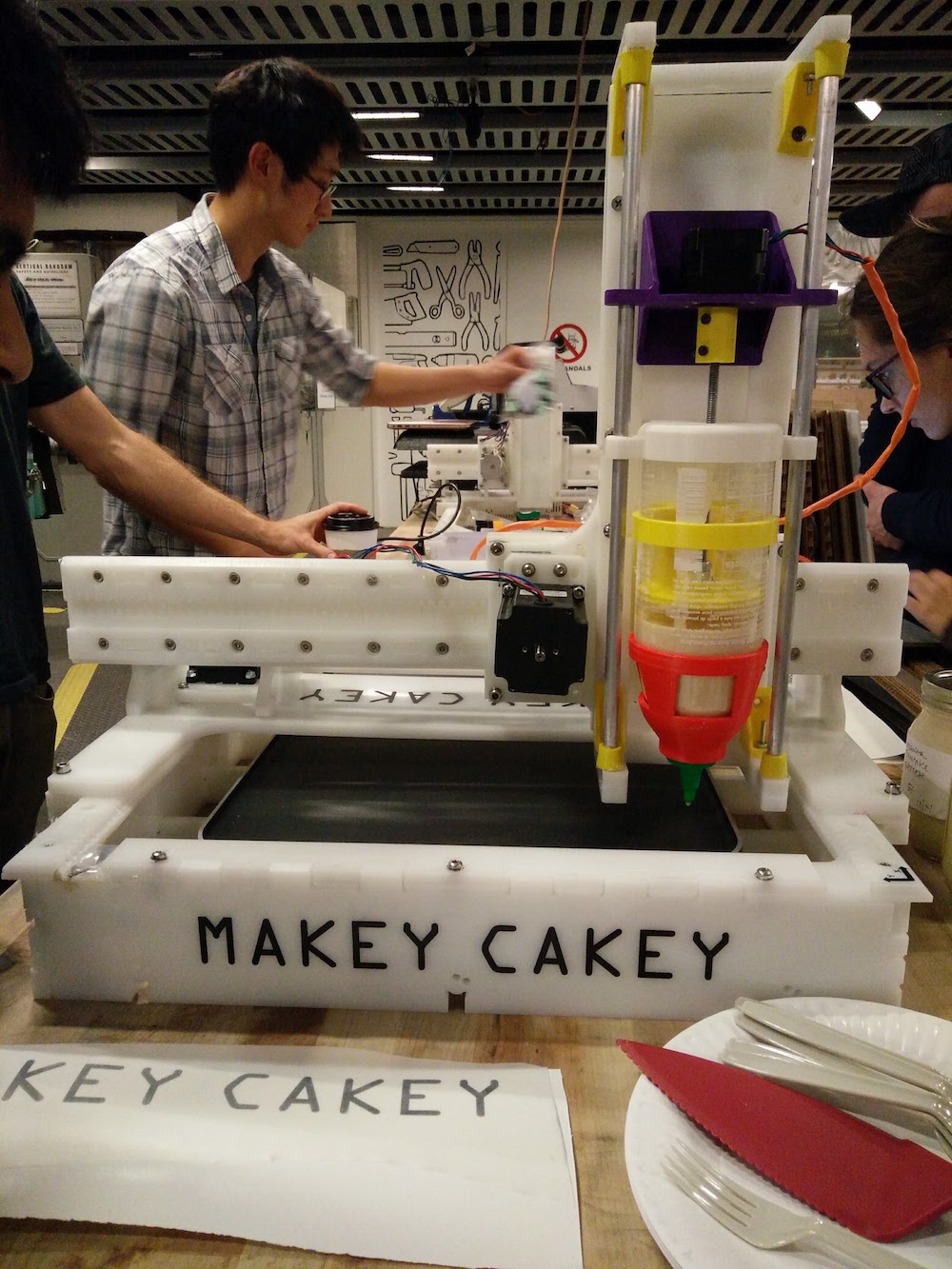
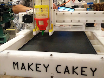
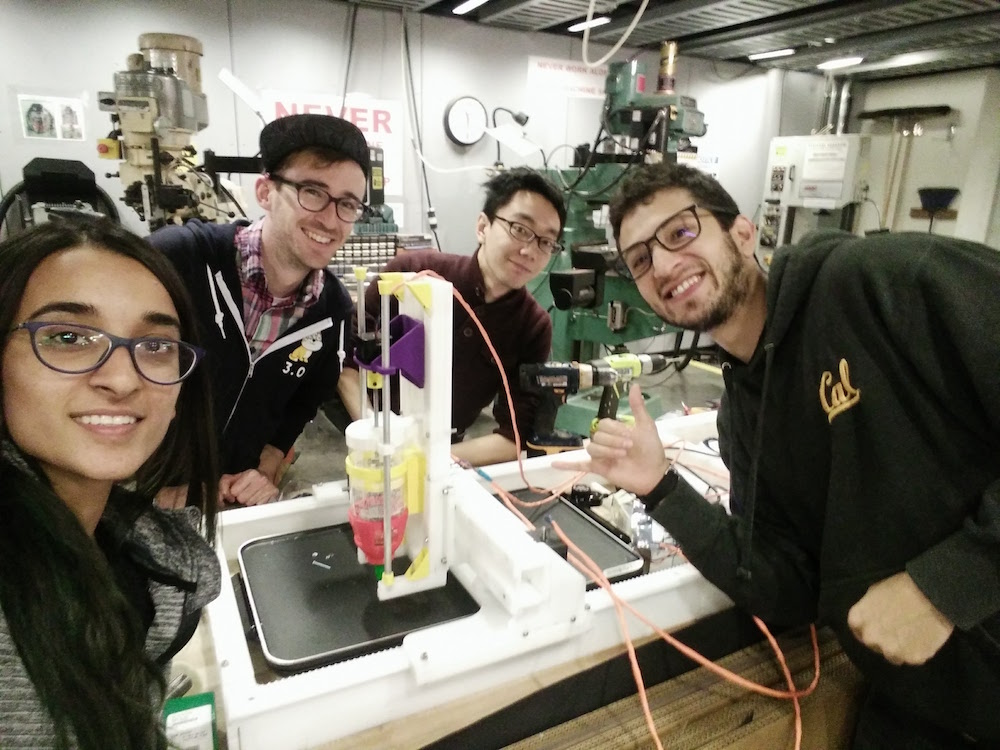
This week's assignemnt was to build a machine (make something, that machines another thing). This was a group project comprising of everyone in the CBA section of the class. After careful brainstorming about what we care about, we came to the conclusion that we all cared about pancakes, and decided to make a pancake machine, ha! We started off very excited about the idea of a pancake maker and divided ourselves into different groups handling different modules of the project. I was a part of the mechanical design. I particularly focused on 1. End effector, 2. Milling (2nd half), and 3. Assembly.
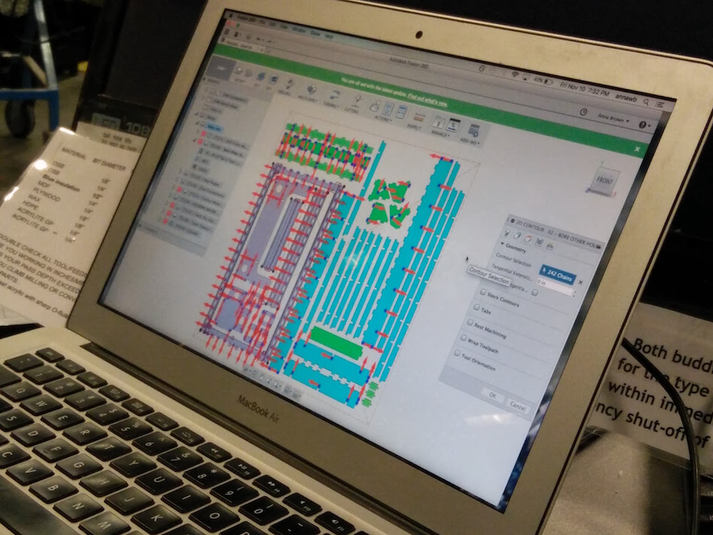
We started by looking at Jake's Fusion files for the machine prototype that he built. Oscar from our team bought a griddle from Amazon that we hoped on using as the base of the pancake machine. Since the griddle size was slightly smaller than the machine bas that Jake designed, Oscar altered the Jake's machine's dimensions to fit in our griddle. But we also realized since the griddle is slightly smaller, we could use the same base size as Jake's. We used the fusion file to lay out all the parts, and Oscar made the edits to some parts. We then used multiple select on fusion to select parts that needed to milled in the same groups (example holes), and used the same order of cutting as Jake's and forme 9 different tool paths. For a lot of the main body, we just used Jake's toolpaths.
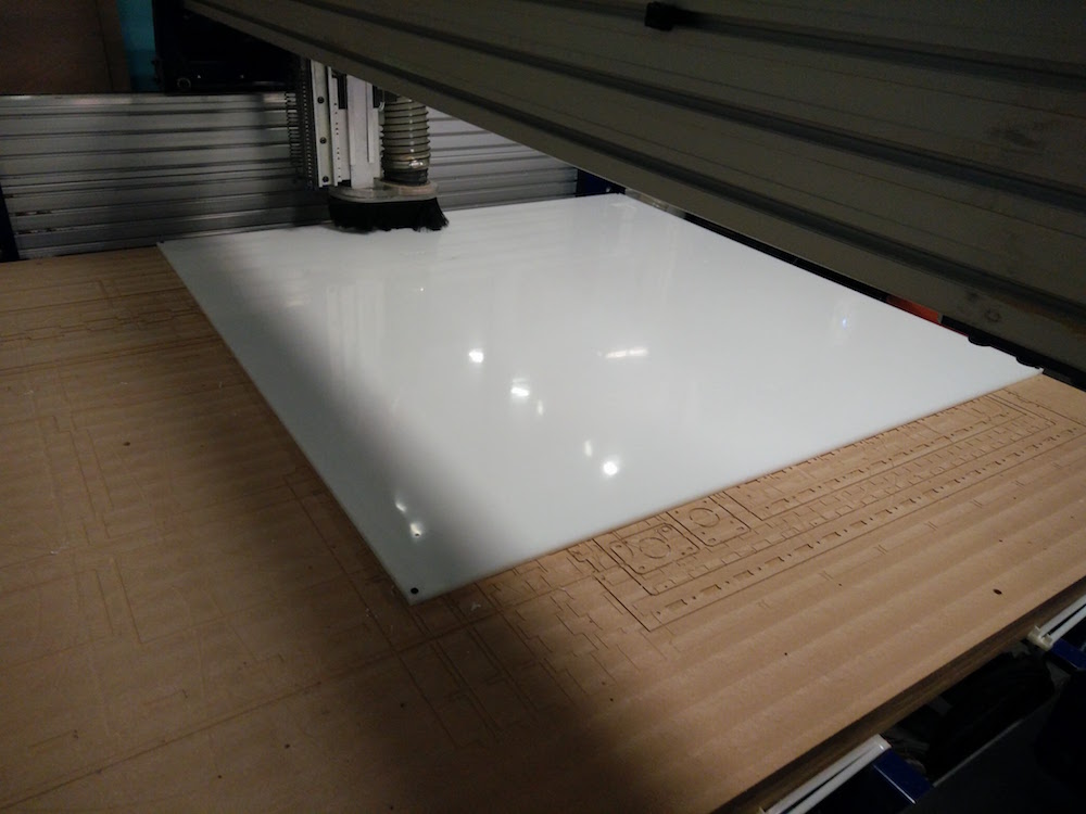
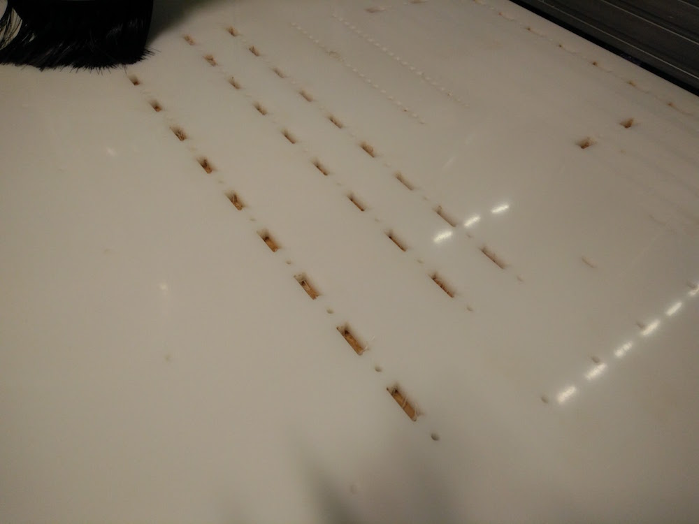
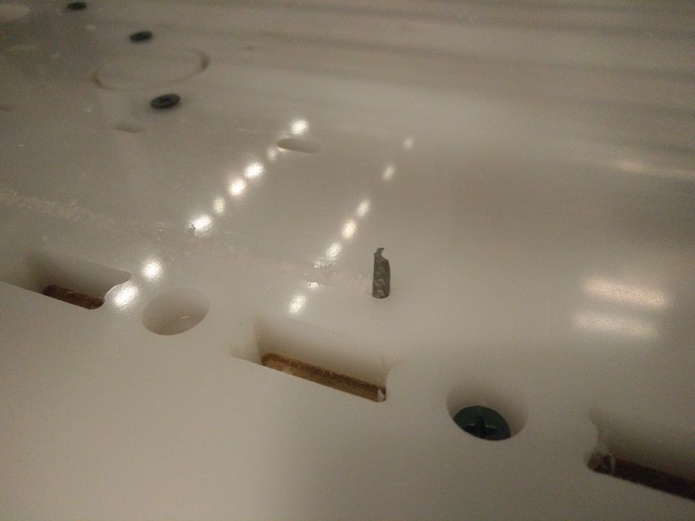
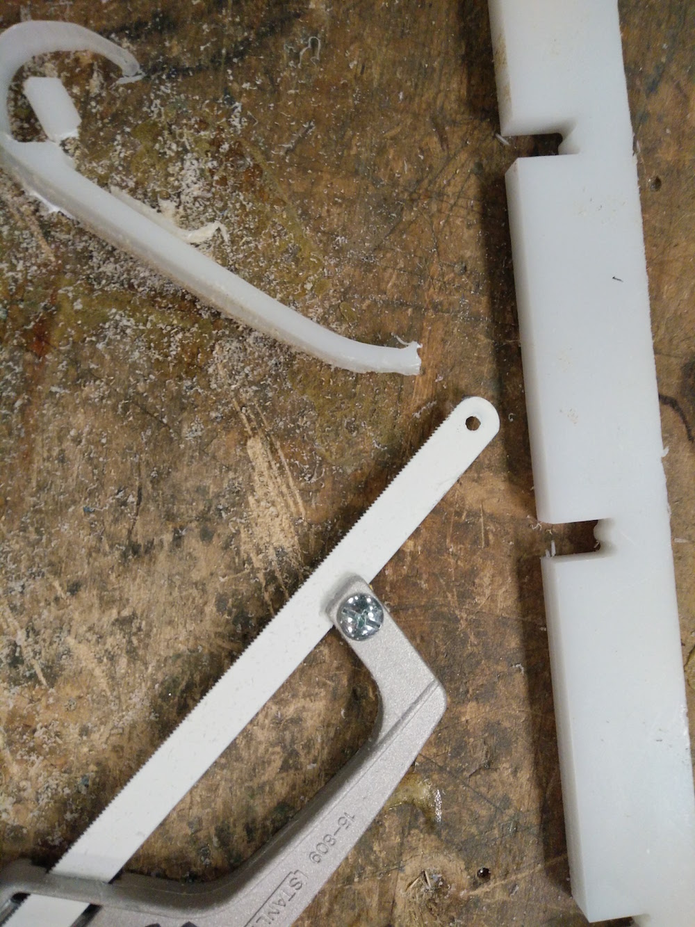
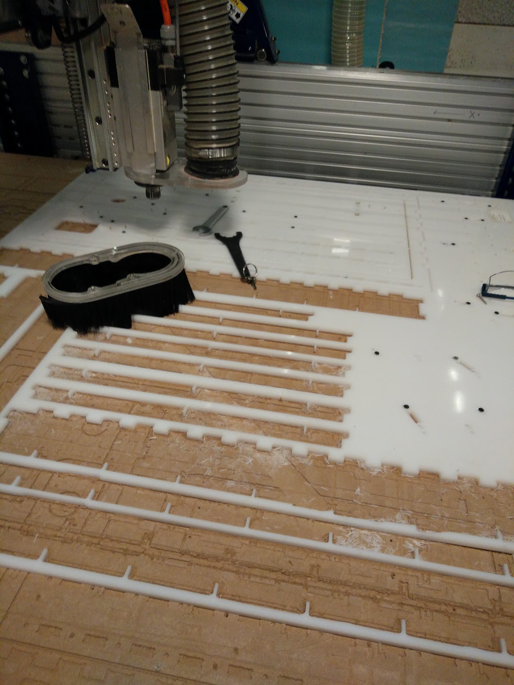
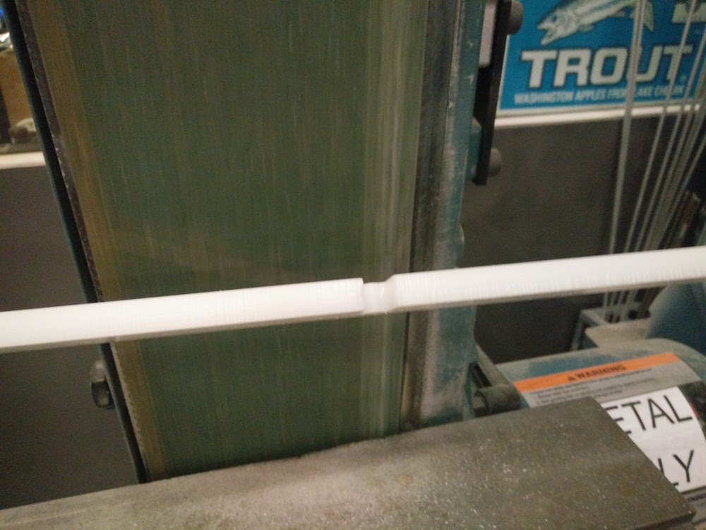
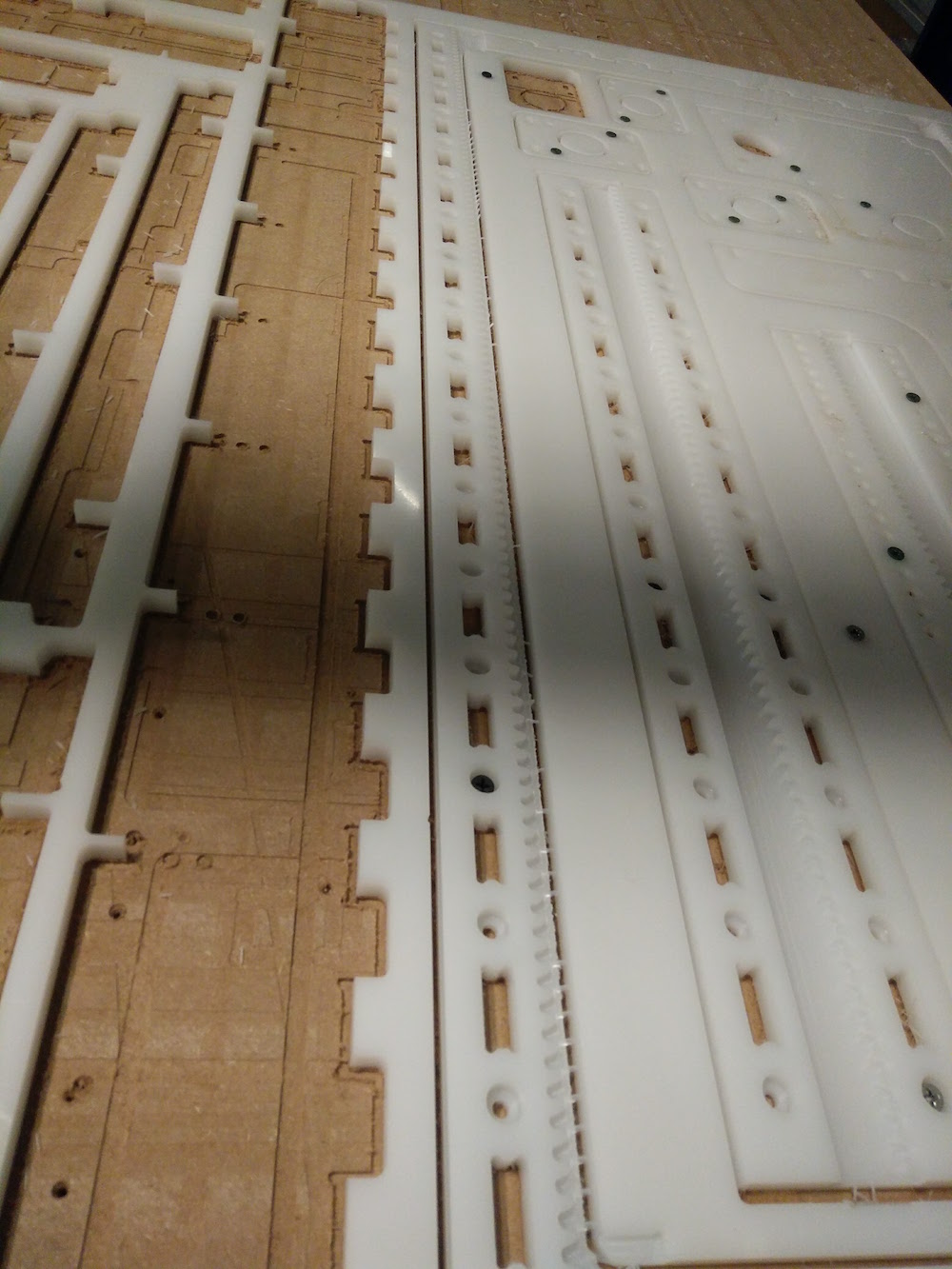
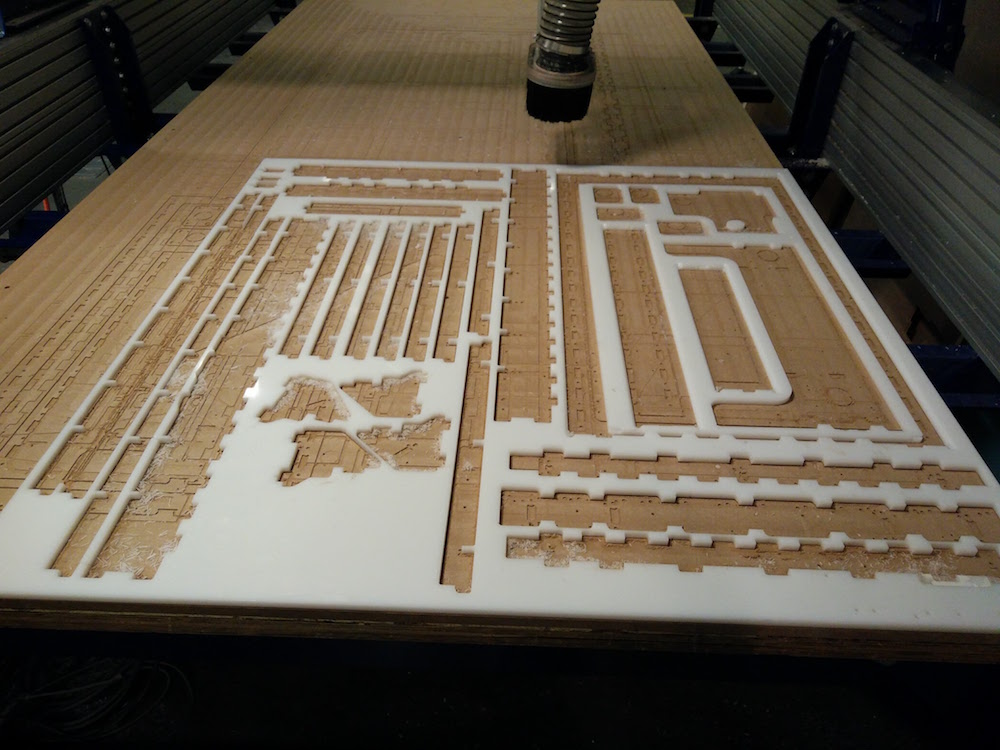
We then started milling out the parts. At first we struggled with some parts flying out and jamming with the drill bit. We also had the zeros move once during the initial hole paths, so you can see multiple hole mill jobs on the parts. So, we drilled in some small parts to the bed using nails. Everything went right till we reached the long parts of the base. They moved slightly since we hadn't made connections in those, and they moved while the mill did the round 2. But we were able to file those parts later using the metal filing machine. We also drilled down all of the other small parts on the sacrificial layer. We ended up breaking the 1/8" tool 4 times while doing our path 6. One of the times we used an incorrect type of tool. One of the times we reduced the RPM. One of the times it did not correctly zero, and we did not restart the cut. Thanks to Jake for lending us his extra tool. We had to manually file all the thin parts of the machine on the sand finding machine. Some parts also needed us to hand saw out extra attachments.
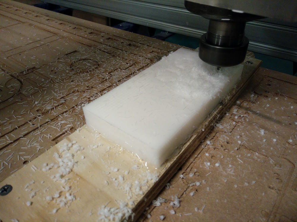
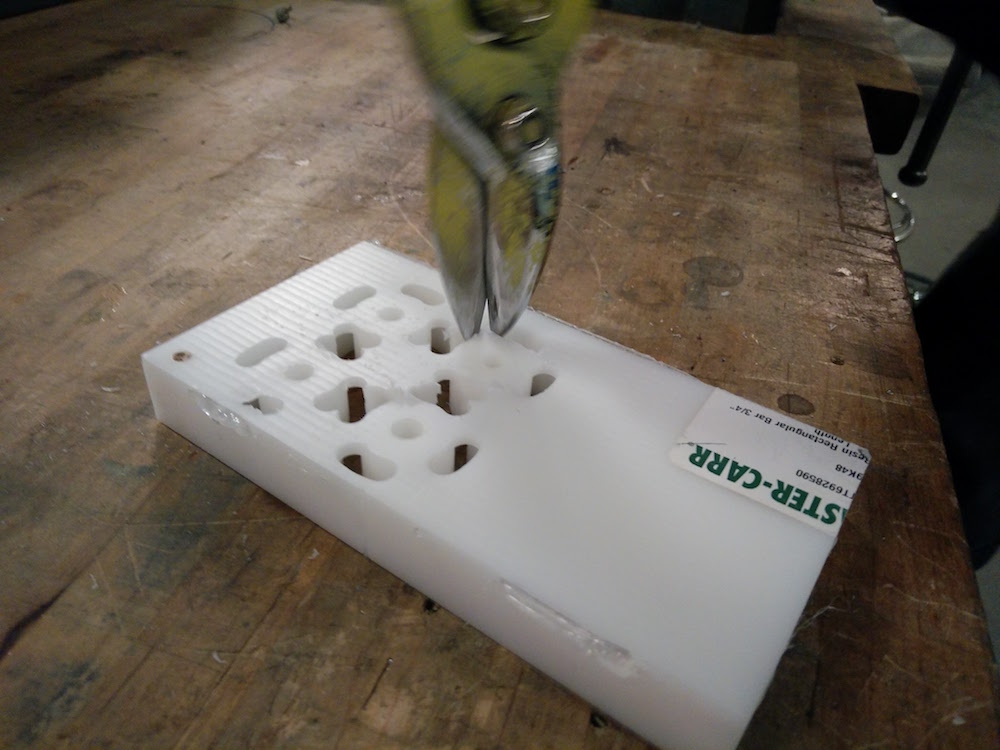
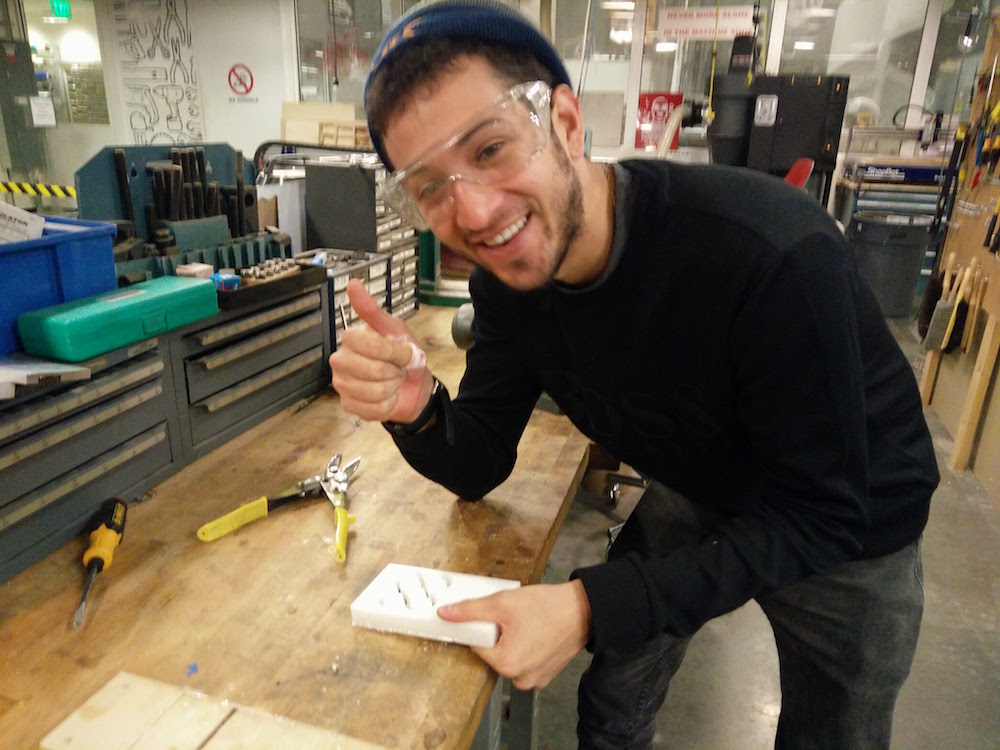
We also used the small Acetal sheet to mill out the motor pinions. They used 3 different tools and were fairly straightforward to mill. The minions were exactly the ones Jake drew. Tomas and I also used a hammer and a knife to remove the oinions from their tabs and I used a metal filer to file the pinions.
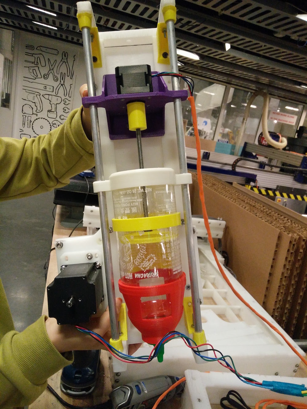
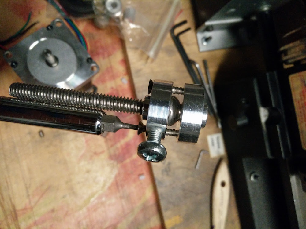
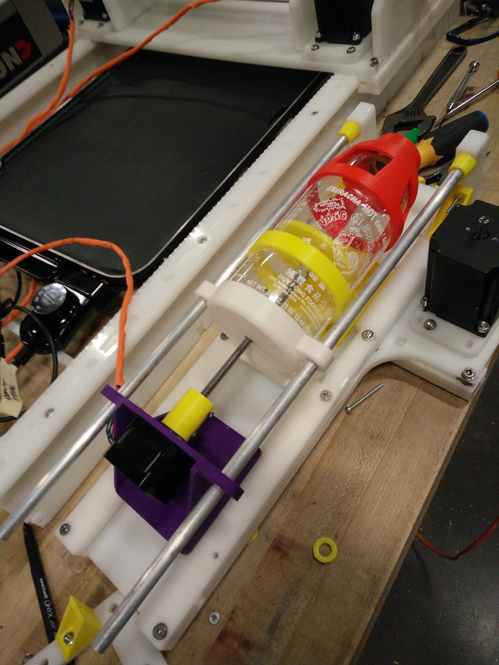
Yun and I took full control of the end effector mechanism for the pancake machine. At first we thought about either using an air pump mechanism or using a tube pressing mechanism. But later we were told by our motors team that it would be much easier for them to control if we just use a stepper motor to be able to use the TinyG. So I have the idea to use a screw and drive mechanism using a stepper motor with a rod extension and a T-nut, and attaching the rod end to a piston that gets pushed down. Yun got in a sirarcha bottle for the pancacke mix. I made a piston of size of the sirarcha bottle by laser cutting and attaching to a rod. I then attached the other end of the rod to the motor using a metal pinion and nuts. We also decided to change the NEMA 23 motor to a NEMA 17 motor model because the NEMA 23 was too heavy. We initially put a little tape around the motor to fix it to the metal pinion, but then since tape bends a little, it was leading to a tilted rod and the piston was not rotating about a central axis, so we ended up 3-d printing a pinion for the NEMA 17 motor. So when the motor runs, it rotates the rod about the t-nut and in effect pushing down the piston since the t-nut is attached in place. Yun 3-d modelled the structure to hold the sirarcha bottle, and I made the motor and rod part of the end effector. We tested it out with the motor controller and it seemed to work!
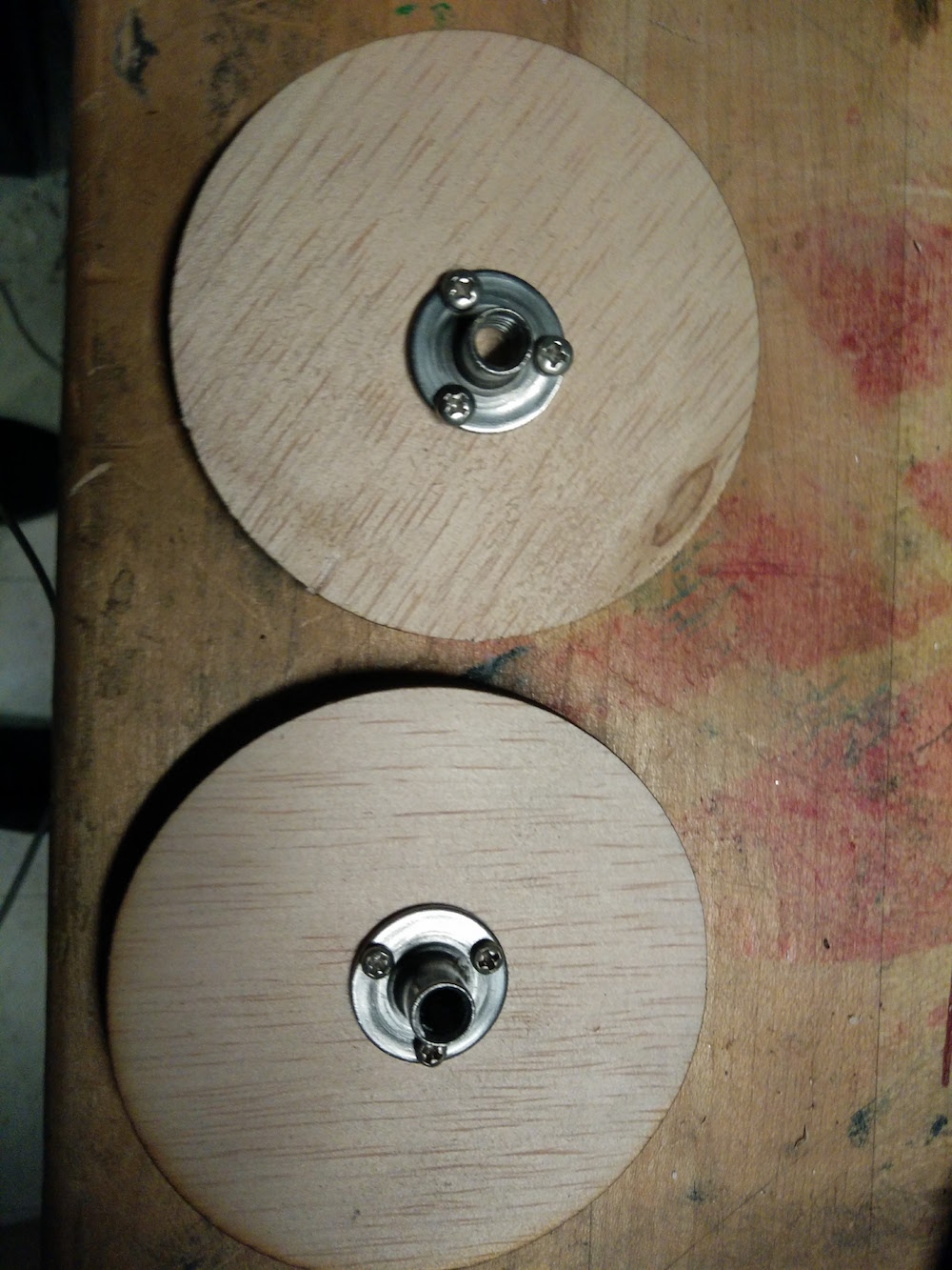
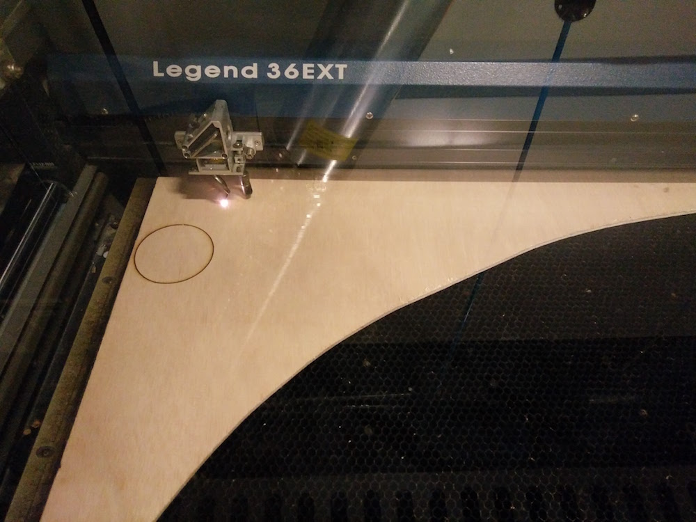
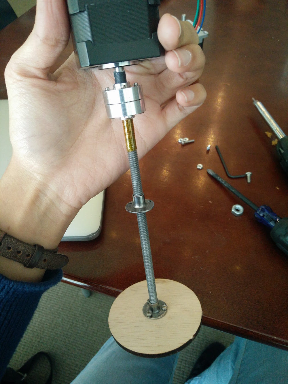
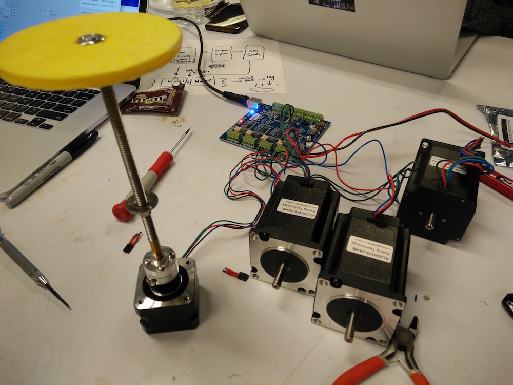
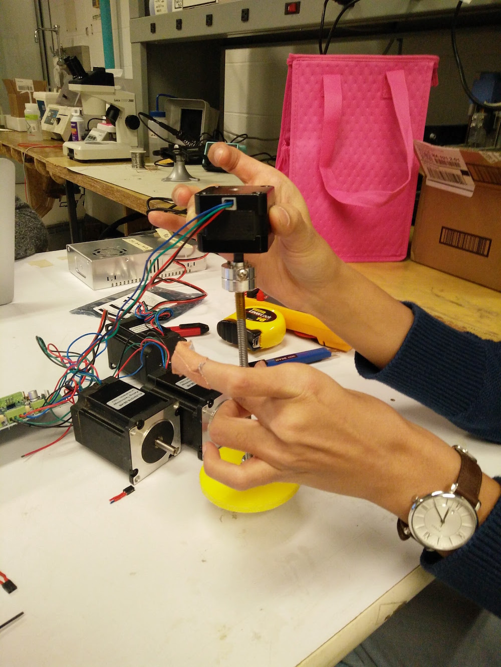
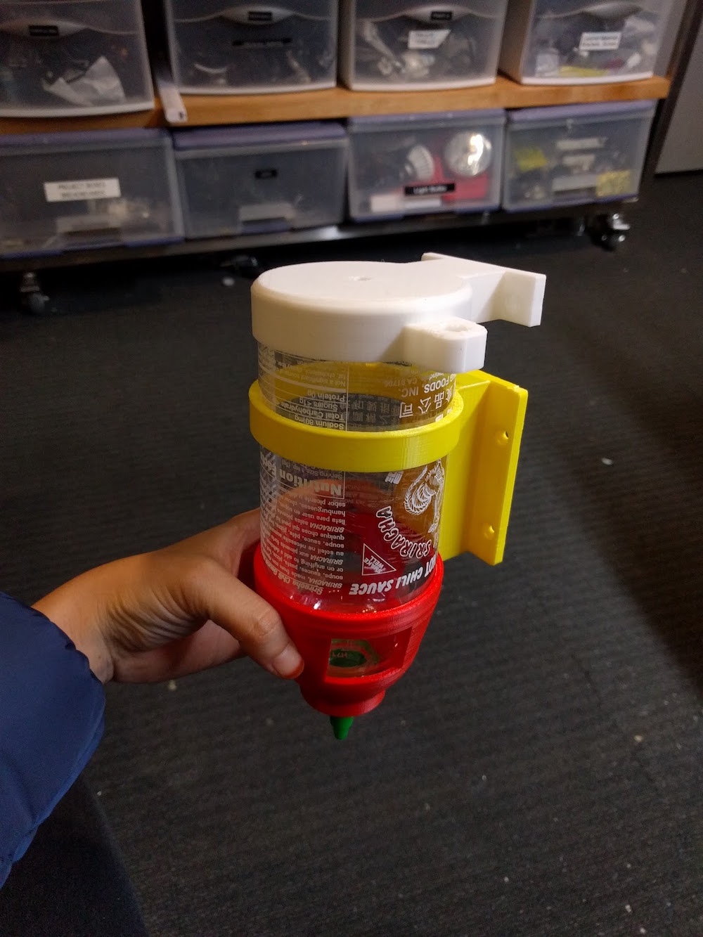
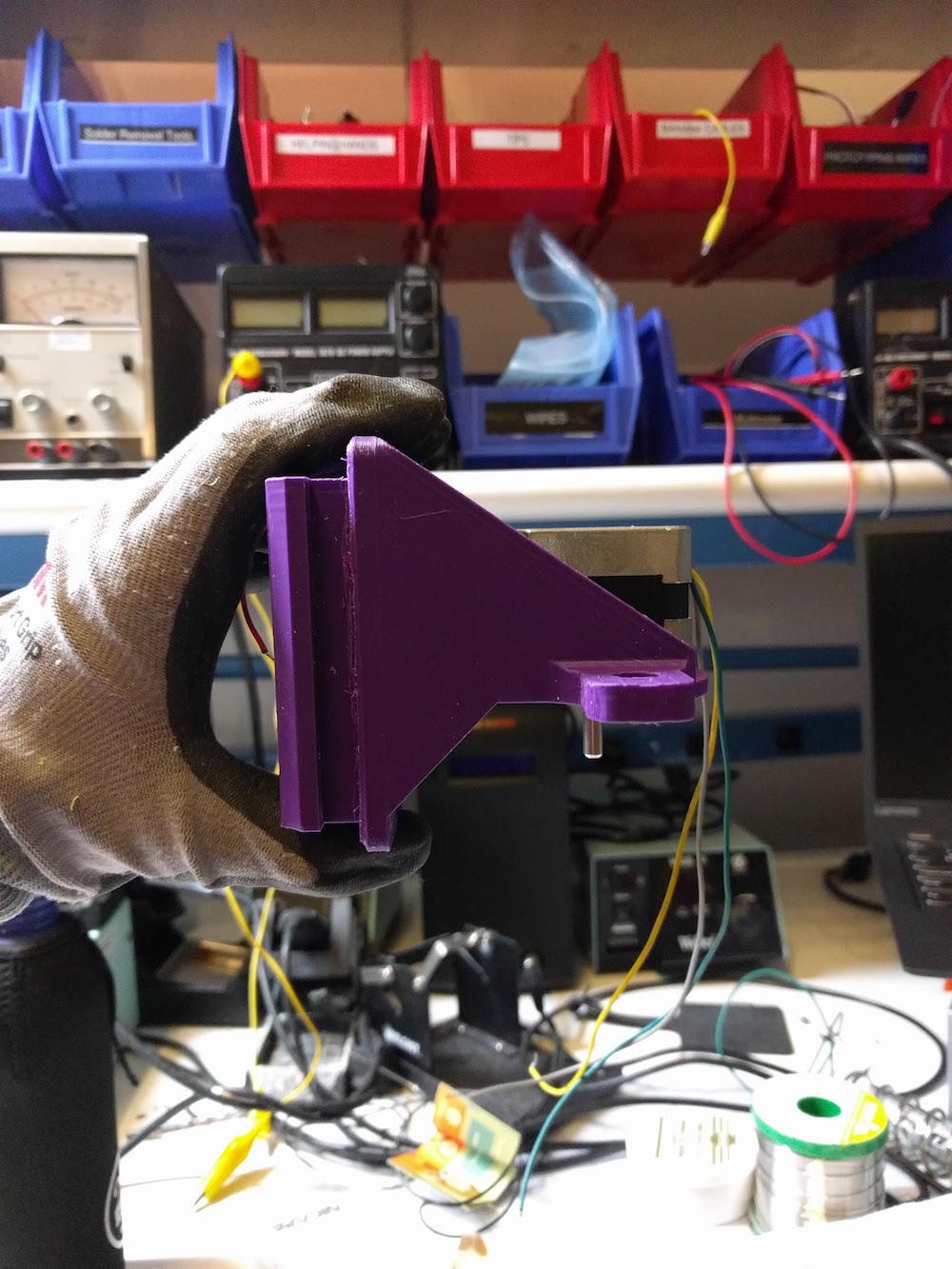
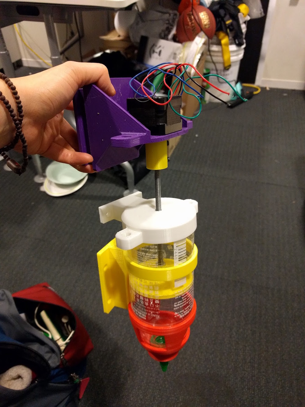
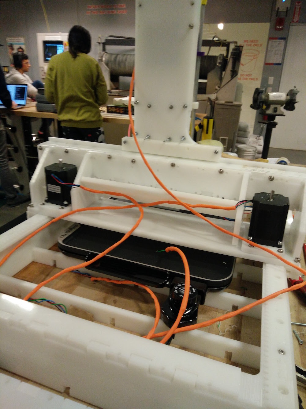
The other part I worked majorly on was assembly. I started with assembling the base the night of the milling. When I attached the walls to the base, it because wobbly. Next morning we decided to let go of the vertical beams as the base was pretty stable on just the walls and the horizontal short ribs. We then made the top two parts, one that holds the y-axis motor, and one that holds the end effector.
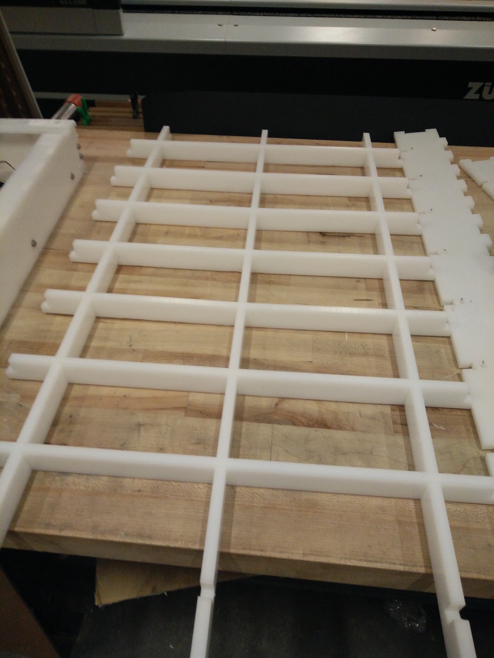
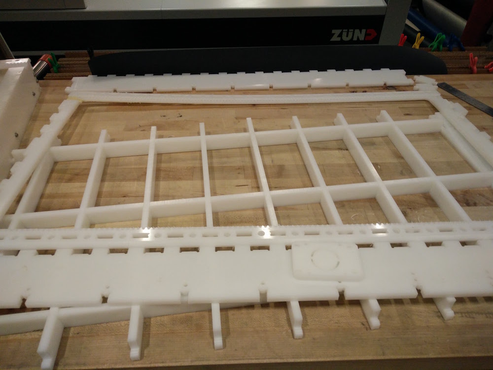
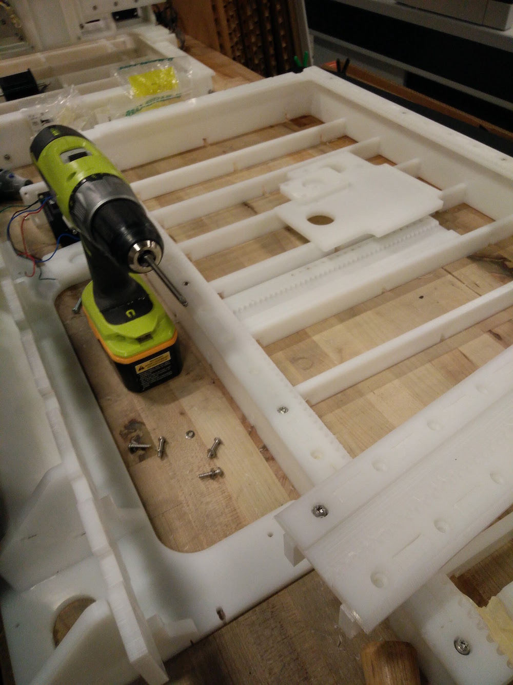
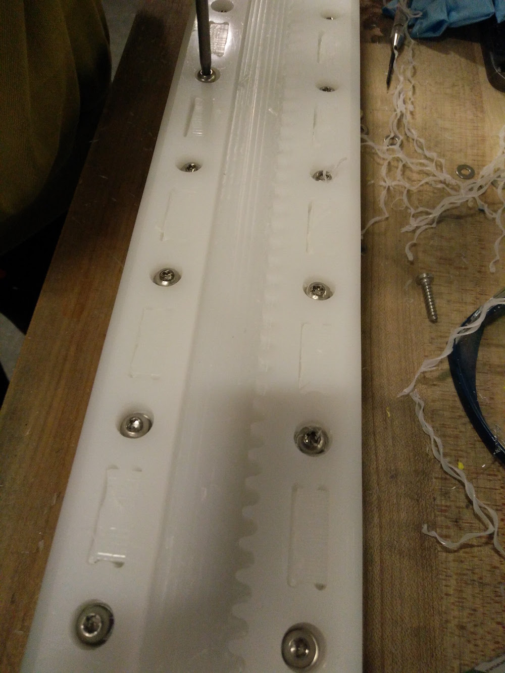
While inserting the y-axis part along with the end effector on top of the horizontal base, we realized that it was getting to heavy and bending the whole thing down towards the base - so we had to nail in the triangular parts to the vertical walls of the y-axis motor part. So as you can see we drilled in extra holes using a hand drill, and put in nails to hold the y-axis motor and end effector in place. We also realized that the pinion was not touching the teeth of the sliders, so we had to remove and move the motor slightly up by half an inch and drill new holes.
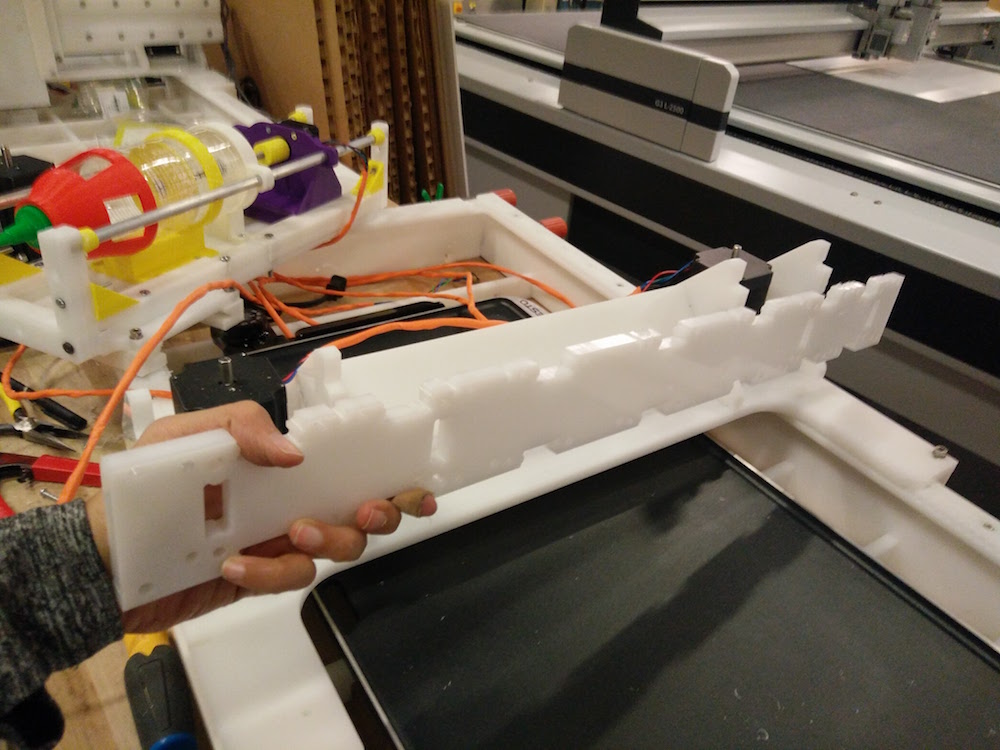
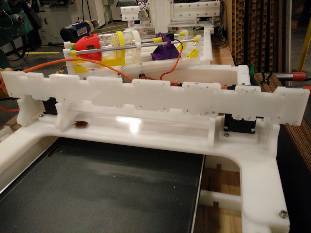
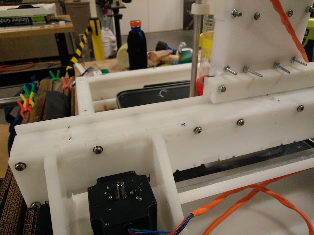
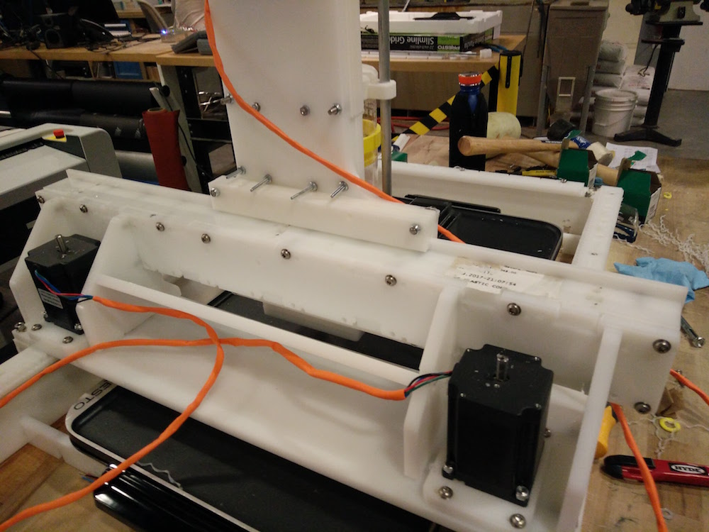
We then put together the end effector part. We needed some amount of removing and glue gunning or the corner yellow triangles since it was tough to hold them in place. Throyghout the body we did a lot of extra nailing to be able to hold the body parts together. I then helped Shawn test out all the 4 motors in the physical structure. The z-axis motor did not work. We tried to troubleshoot by relacing the y-axis with the z-axis extruder motor, and it worked. So, we realized that it only needed reconfiguring of that motor. After configuring it, all the axes worked and the machine was functional.
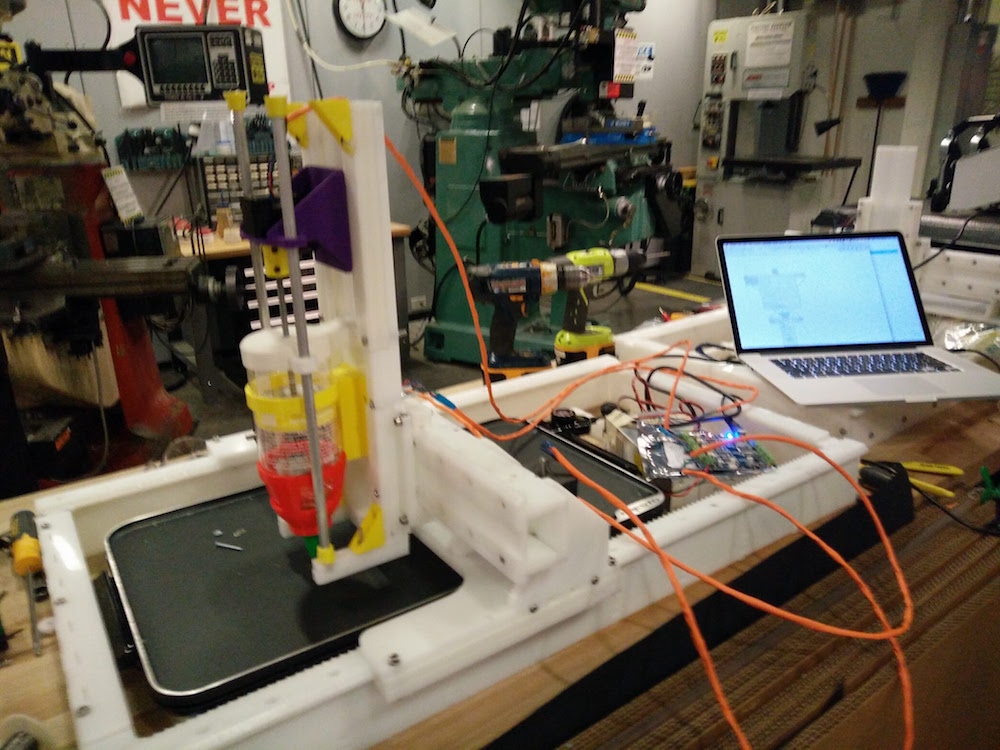
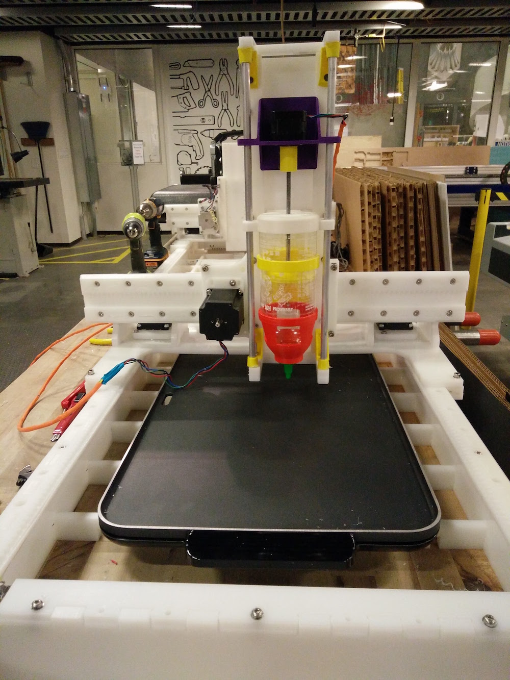
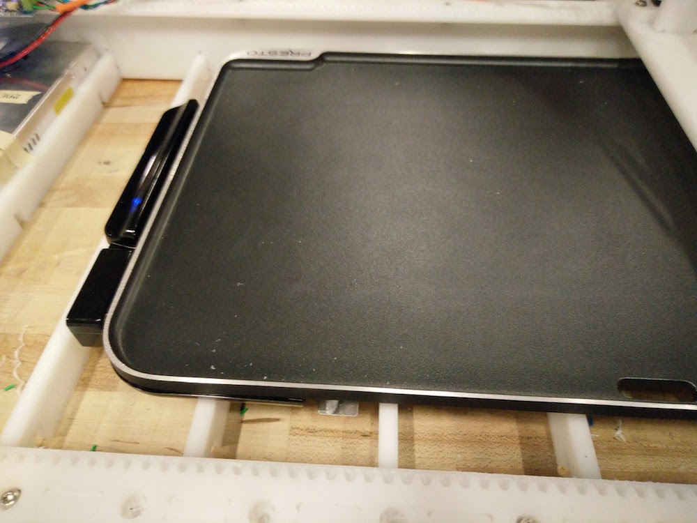
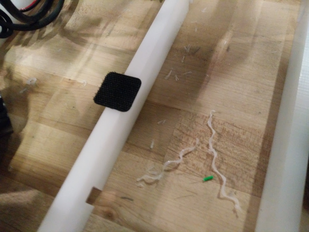
We then used velcrow to stick the griddle to the bade and hold it in place for the pancakes.
Input Devices
This week was about using input devices (sensors) on our boards to get some kind of input information. This week for me was good learning about very basic stuff such as how analog inputs are converted into digital values, what different pins in a microcontroller are meant for I2C communication, which input devices require what kind of communication, etc. For my final project I wanted to explore making an emotional painting machine, so I wanted to play with a heartrate sensor. Apart from that I also explored with an accelerometer for fun, and tried to get the x,y,z values.
First, I wanted to be able to use the old board I had created in the embedded programming + output devices weeks, and make daughter boards for the sensor setup. This is the old board I had, used an atmega328p microcontorller, and is sort of like an arduino (not completely). I did not really have all the arduino pins on it, since I didn't need it till this point. I only realized at a later point that I would be needing the analogue pins, and the board's SCL and SDA pins will need to be connected to the accelerometer's SCL and SDA pins.

I spoke to Amanda about using the accelerometer first, and since we could not find one in the Electronics lab, I grabbed an accelerometer + magnetometer (LSM303DLHC). I also got an MPU 6050 accelerometer + gyro on digikey, that I wanted to try using.
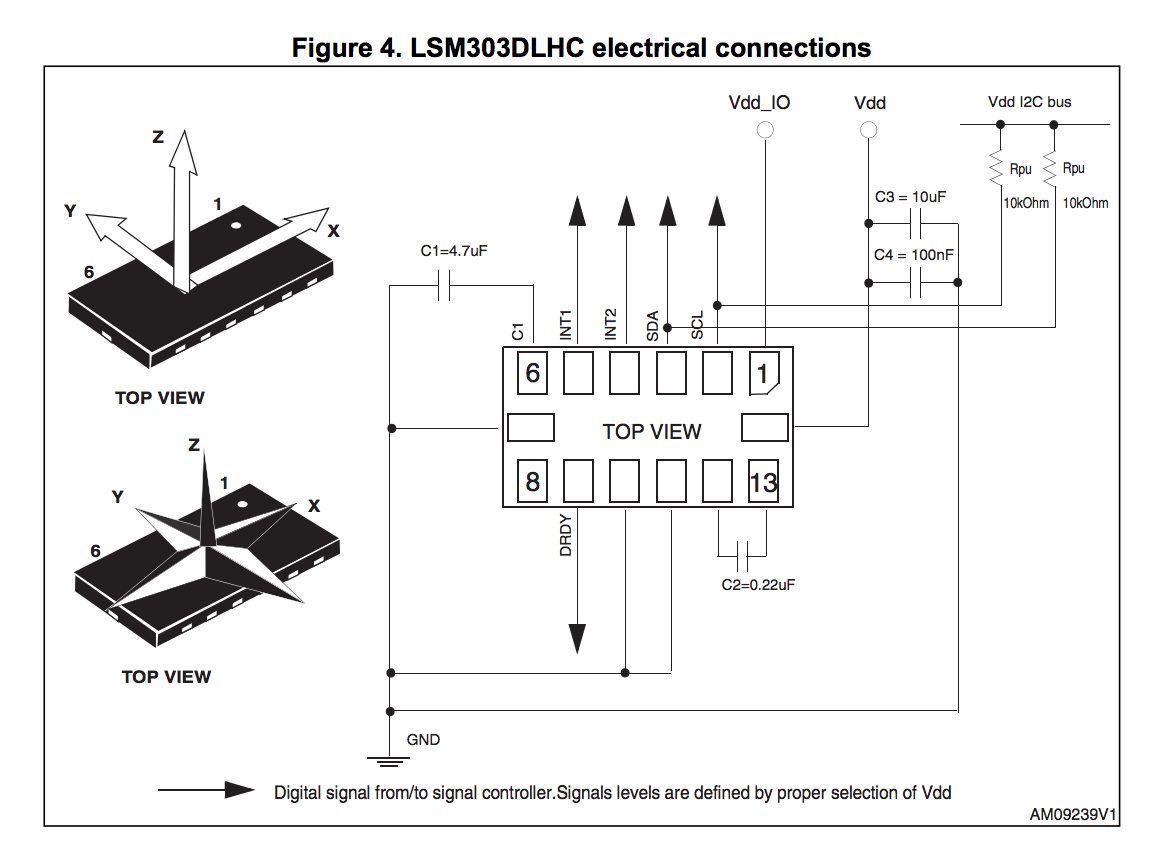
I learned that the pins 2 & 3 on the LSM303DLHC are the SCL and SDA pins, and those would be used for I2C communication. I learned from the data sheet that both of these would require 10kOhm pull up resistors on the 2 I2C bus lines. In addition, I would require a voltage regulator since it is factory caliberated at 2.5 V and can handle a maximum of 3.6 V. SO I first produced the accerelometer board with the LSM303DLHC accelero + gyro. I read some more about how the accelerometer is actually working and turns out it is a ball inside a box with piezos on each wall, and they sense pressure when the box is tilted. Depending on the current produced from the piezoelectric walls of the sensor, we determine the direction of inclination and its magnitude. I thought this was pretty cool, because before this accelerometer was this mysterious cool sensor to me.
Now I had both the accelero + gyro board, and the accelero + magno that I bought from digikey. I had to connect the sensor to my board. I realized that I do not have pins for SCL and SDA on my board. I also wanted to connect the MPU6050 to the interrupt pin of my board (which was pin 32 of my atmega328p, that I had not really produced headers for). Instead of making new boards, I just soldered some header pins and wires directly onto my board. I used some glue gun to do the fastening on the board. Soldering wire onto the traces of the atmega328p was fairly difficult because the traces were so tiny, but I borrowed the 30 wires from Conformable Decoders and could do it. On retrospect, I should just have made a new board.
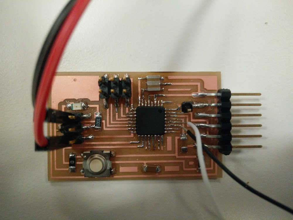
I first plugged in the MPU6050 to edited board. I connected the SCL , SDA pins to the SCL (pin 28), SDA (pin 27) on the atmega328p. I also connected the MPU6050's interrupt pin to atmega328p's interrupt pin (pin 32). I tested the MPU6050 with a simple arduino test code, that uses the serial plotter to plot the xyz values. The sensor worked fairly well - only it needs a little time to stabilize (around 5-10 seconds), and is very very sensitive.
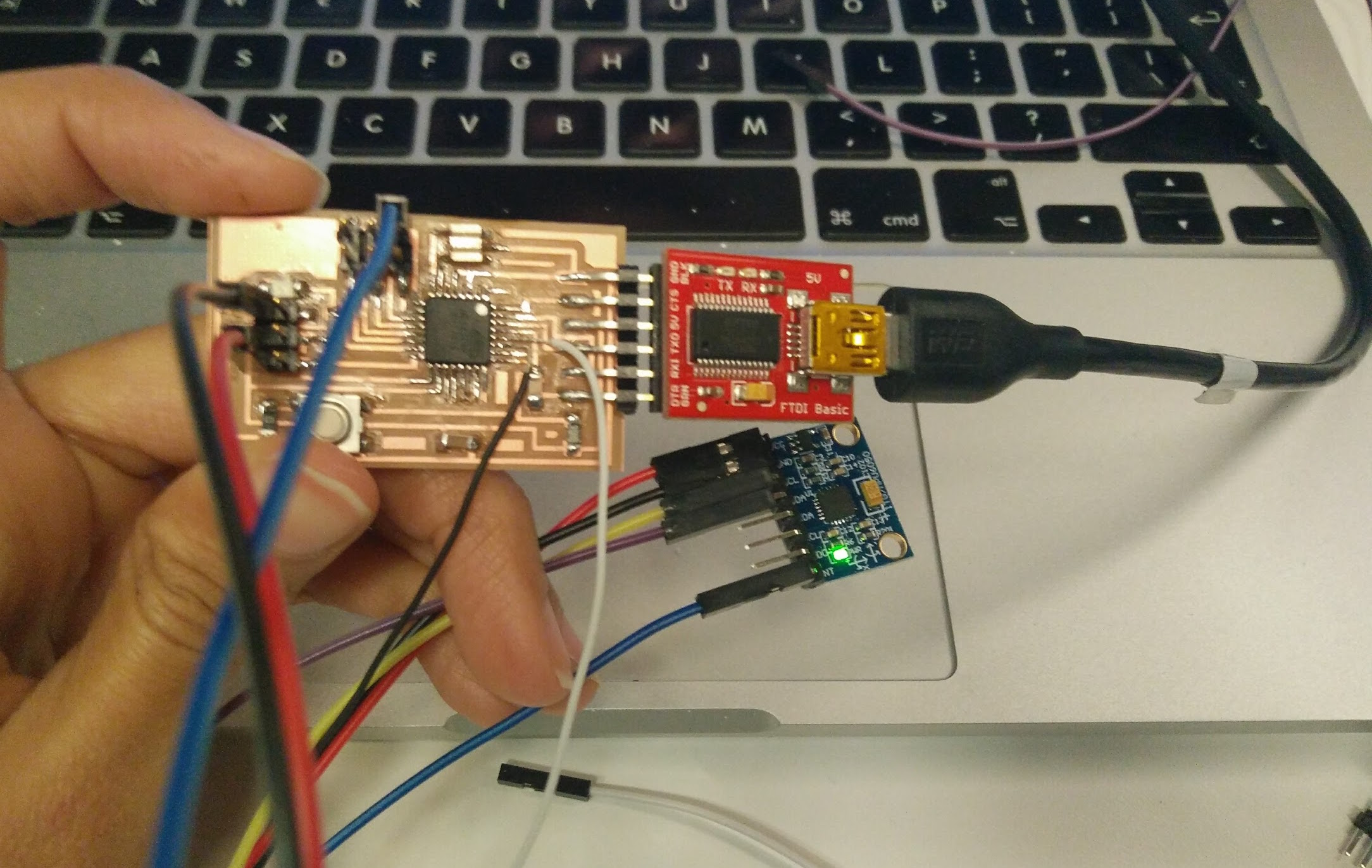
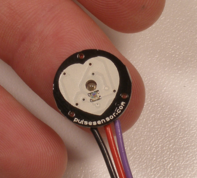
I also wanted to play with the heart rate sensor. At first I thought about making my own heartrate sensor, and found this tutorial that uses an LED as an excitation source and a photoresistor as a method of measuring variation due to heartate. I used this tutorial to get started. However, I also could not find the photoresistor they used, and decided to go ahead and get the more robust SEN-11574 Pulse Sensor from digikey, because I will need it later too.
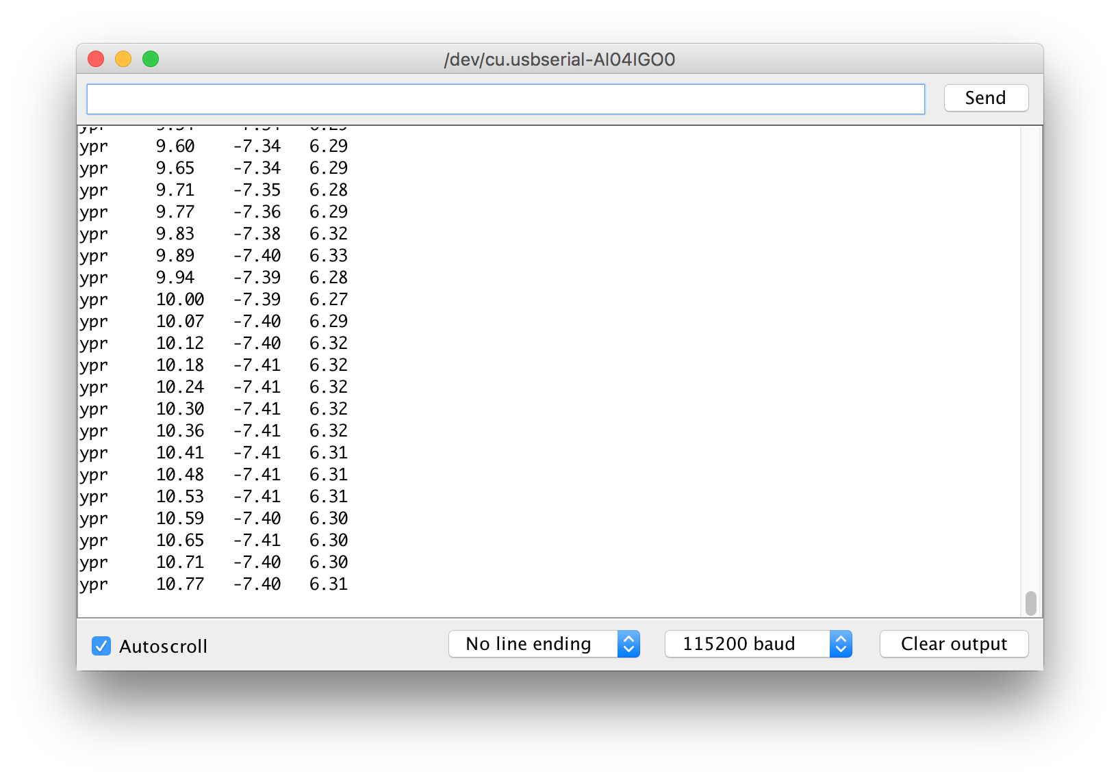
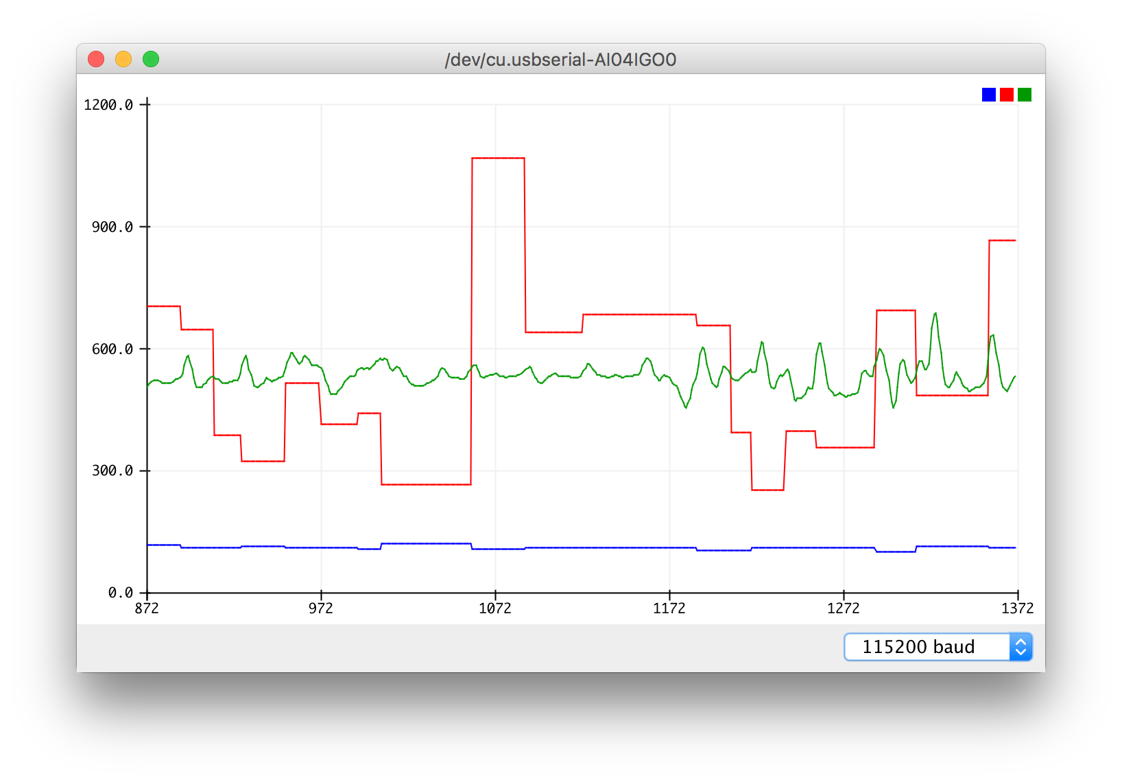
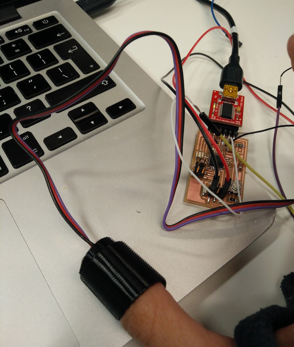
Since I had already edited my board to add extra wires on analogue pins to accommodate SDL/SDA, I used one of those to (pin 28) on the atmega328p to get analogue input from the heartrate sensor. I tweaked someone else's arduino code of using the serial plotter to plot the heartrate of the user. I also did a Processigng sketch that visualized the heart and variations in heart rate. However, I also noticed that the heart rate sensor is not completely reliable, and some times stops detection for no reason. I now plan to go back to creating my own heart rat sensor, and have it be more robust.
Interface and Application Programming
This week was about programming a software application that interfaces with an input or output device from previous weeks. Since I want to be able to visualize affective data, I chose to interface with 1. Accelerometer, 2. heart rate sensor (I used my board from the embedded programming week and the heart rate sensor that I got for input devices week) and 3. camera (I just used my computer webcam). I also wanted to learn to use processing to be able to visualize data I am getting from serial communication.


With the accelerometer, I did the most basic x, y, z monitoring in Arduino's serial monitoring interface to make sure I am getting the correct values. I was communicating using the I2C pins on my board that I fashioned (since I had initially not made those pins). I used Arduino IDE's serial monitor and serial plotter to look at the data. Note that you need to set the baud rate correctly to 115200 baud.
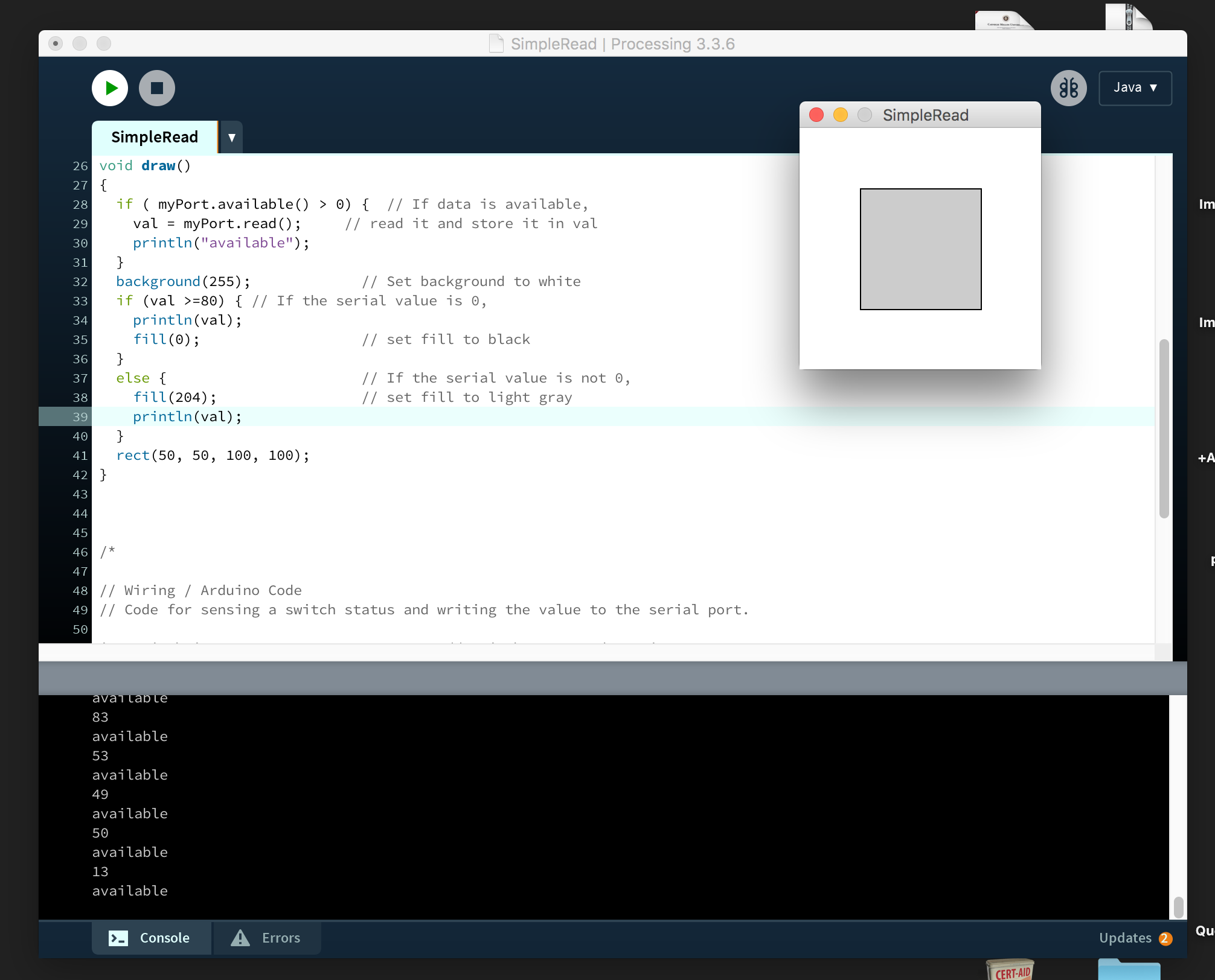
With the heart rate I first used the Processing IDE and used the SimpleRead example program to simply read from a serial port. It took me some time to figure out how to number the serial ports, but it recognized the sensor and printed our sensor values. I made a simple rectangle that changes color whenever there is an input value greater than a certain base value that you can change.


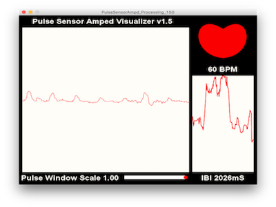
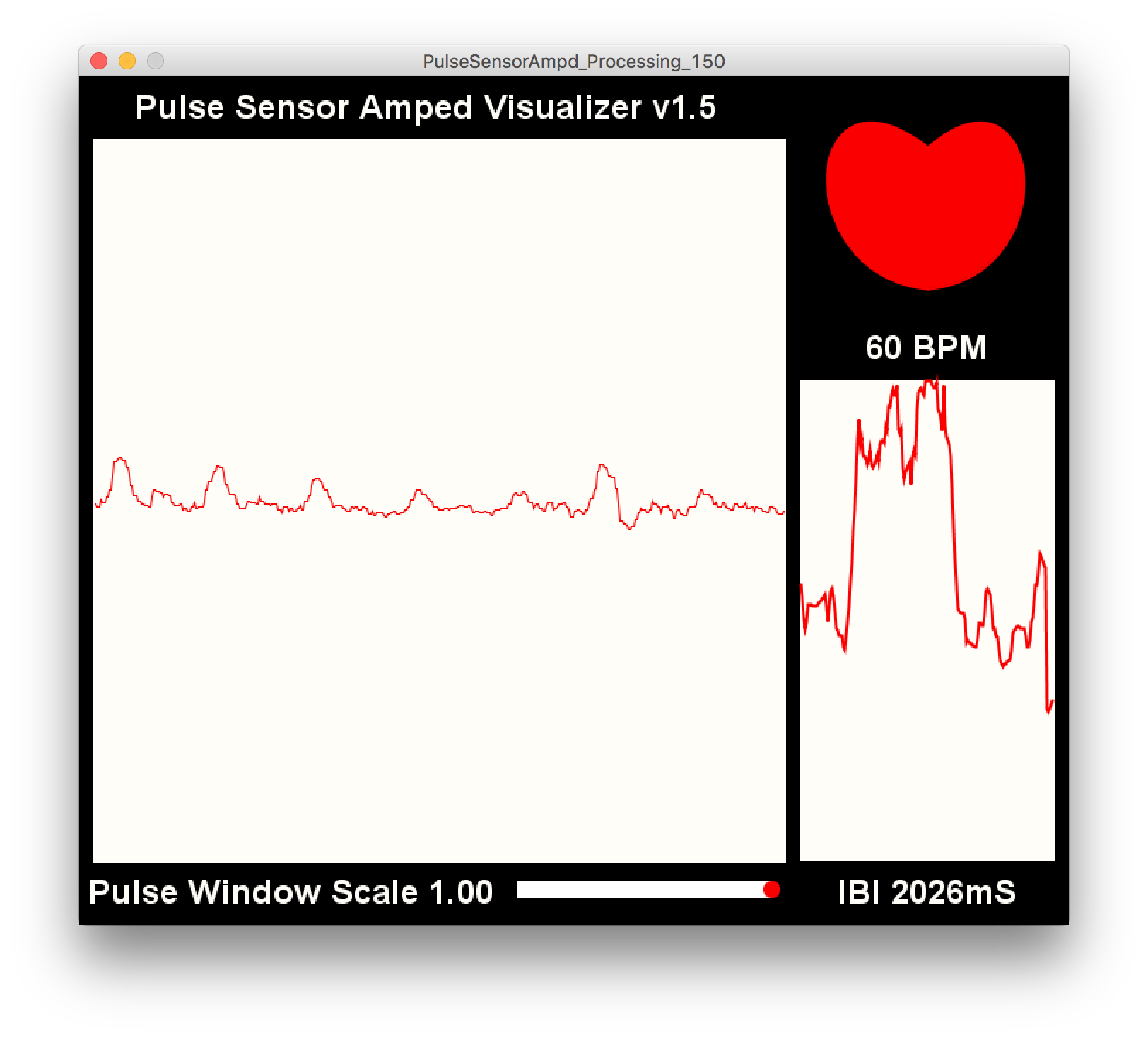
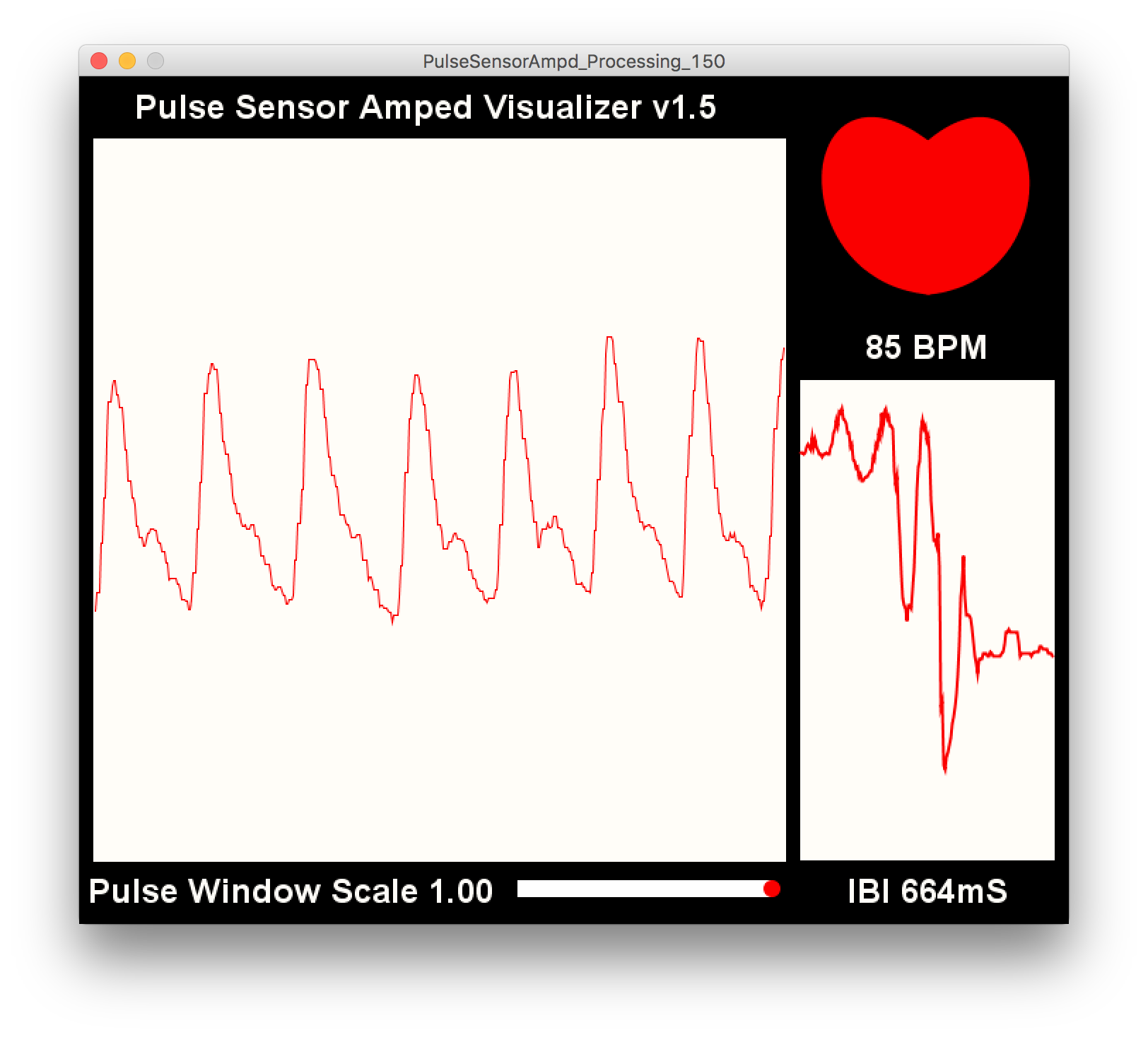
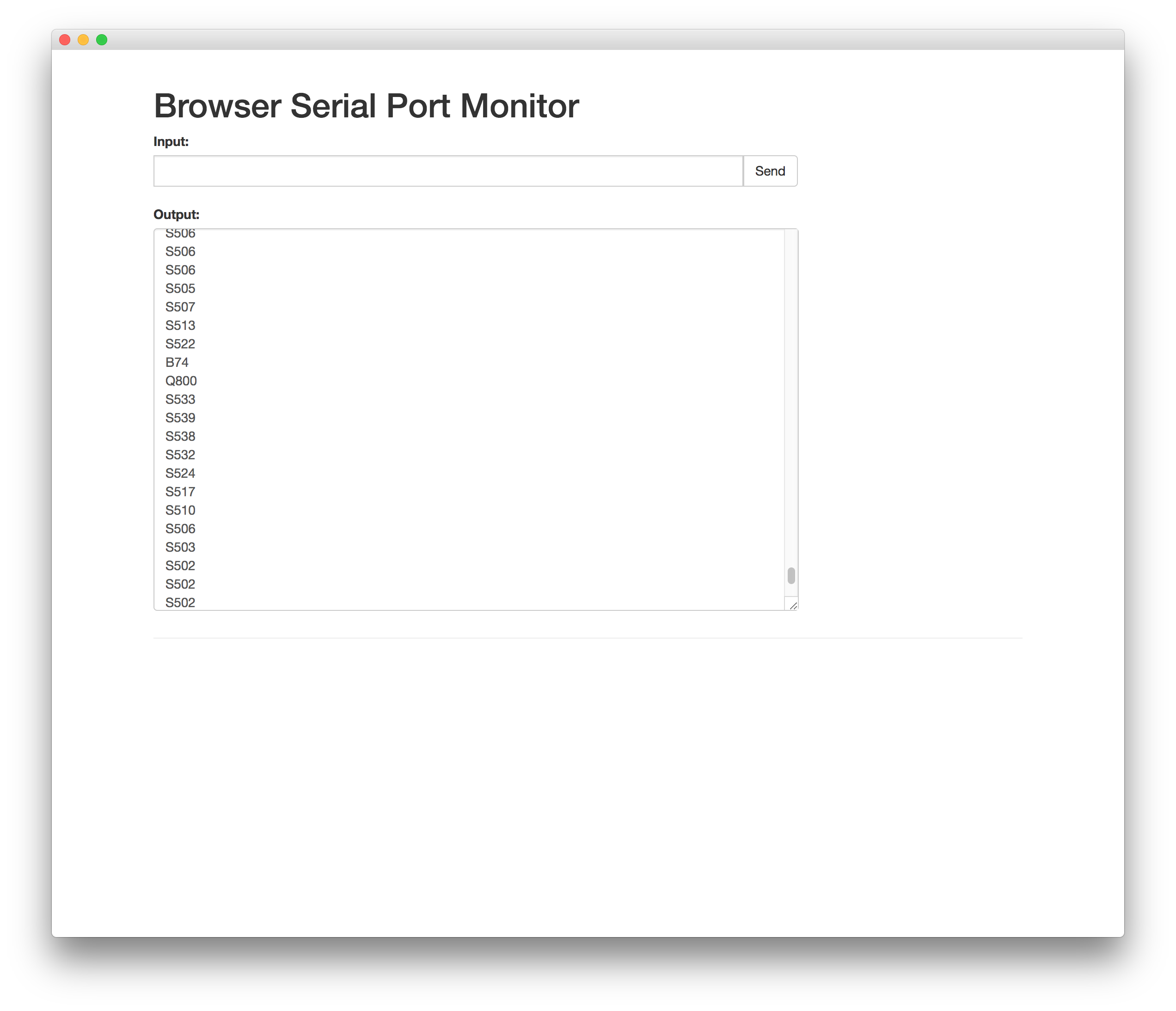
With the heart rate sensor, I used the Processing IDE to visualize heart rate data. The sensor is basically an IR light + receiver that shows high when the heart beat is detected. I am blinking the pin 13 on the LED whenever high signal is received. It then takes the frequency of high to calculate the BPM value. The Processing sketch beats the heart every time the heart pulses, and the displays the BPM. The graph shows the beats. The second mini graph visualizes the time interval between any two beats (IBI). If you look in the serialEvent part of the Processing code, it takes the raw sensor values (that begin with B, S, Q), removes their first character, converts them into a usable int. This gives you the sensor data, BPM and IBI.
 Processing Source Code
I also used Serial Monitor, Chrome's serial monitoring plugin called Serial Monitor that reads from serial ports, with the heart rate sensor. It seems to work fine, just be careful about your port path. It is super easy to use and I am hoping to use it for future web apps that need talking to external input/output devices.
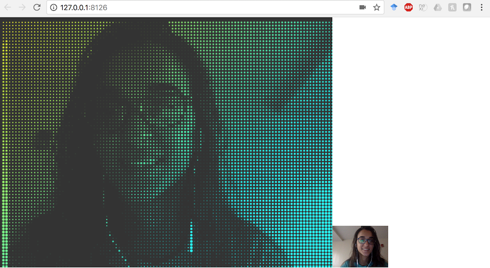
I also wanted to make something that uses affective data and visualizes it. I thought Processing would be an interesting took to make this. So I took affect data from the webam live video input and analyzed it using the Affdex SDK. I also converted this live video into a pixel mirror. I then changed the aesthetics of processing particles based on the person's affect. For example, in the images below, the colors of the partciles change based on how happy the person is.
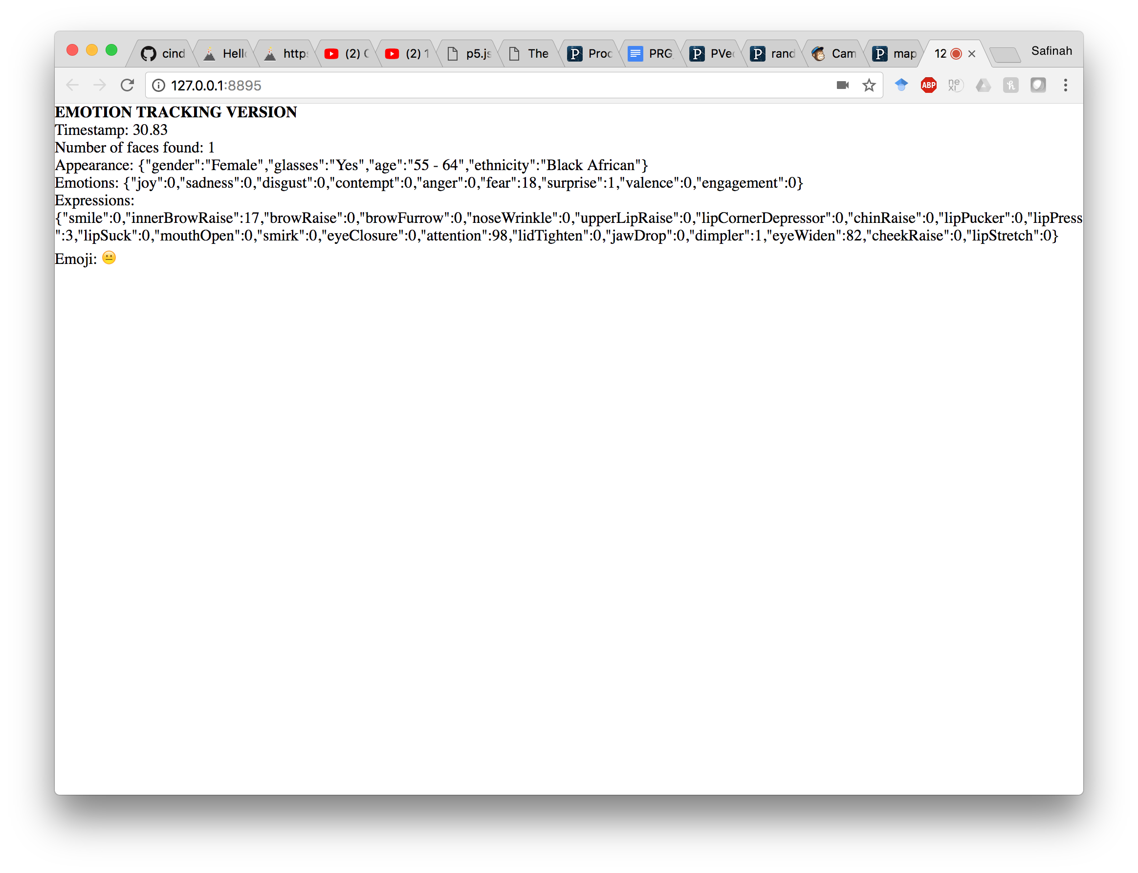
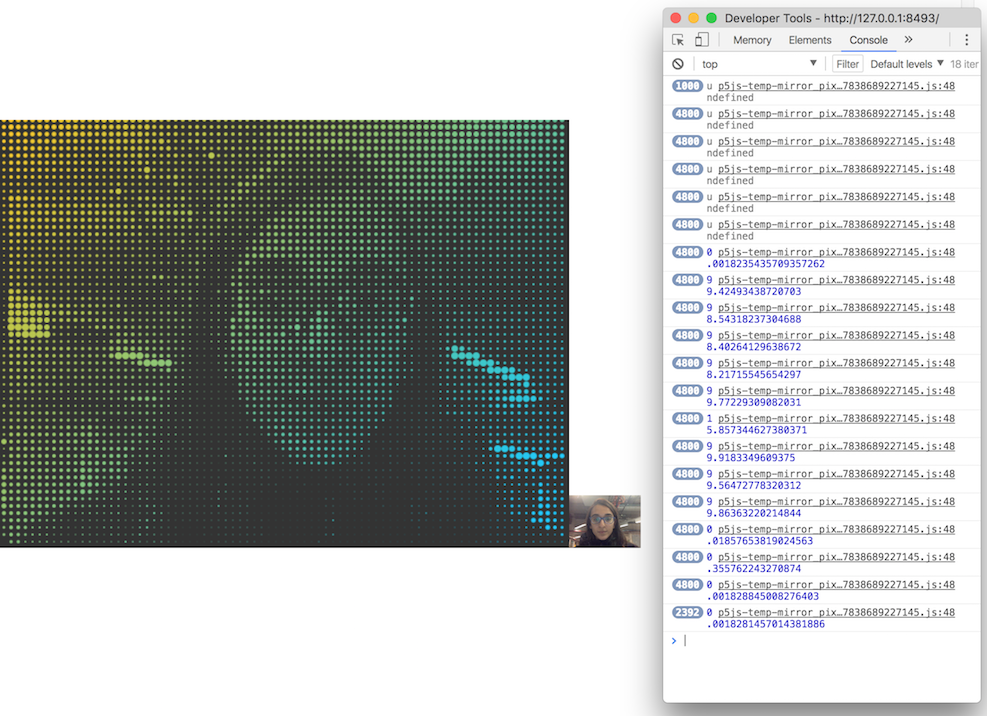
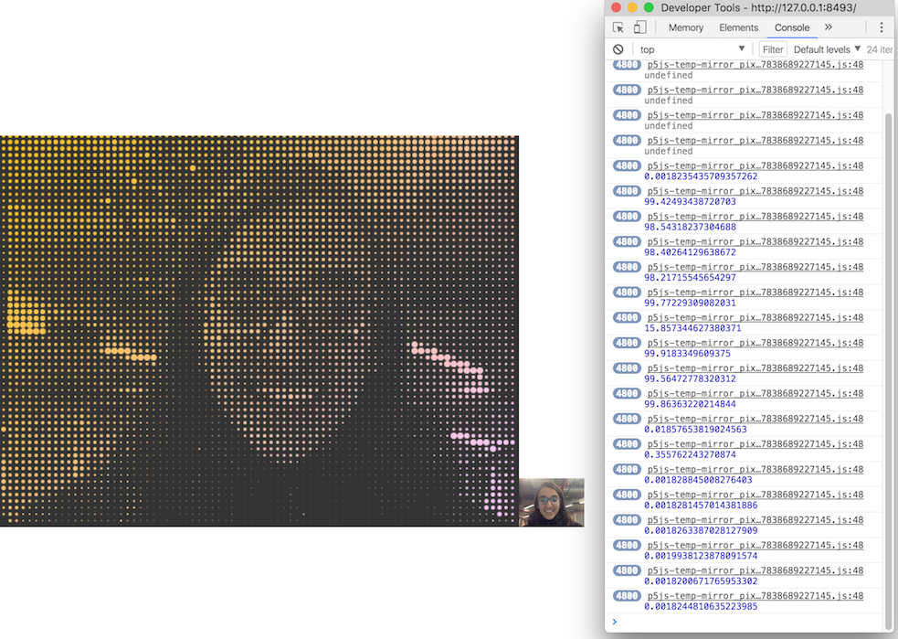
I plan to integrate the affect analysis from heart rate and audio into other forms of visual aesthetics such as particle motion, speed, etc. I also plan to move this to LED's instead of Processing.
Processing + Affdex in JS source codeNetworking
This week was about learning the very basics of Networking for me. I explored the I2C networking, what the I2C pins are on the Atmega chips, how to get two boards to talk, and how the information flow happens.
At this stage, I was trying to use the heart rate sensor and accelerometer for my final project to be able to make an emotional physical machine (that I did not end up doing because 3d maps got me excited last minute), that uses heart rate for arousal, and accelerometer for motion. So a lot of what I did this week was a repetition of the Input devices week, where I used the I2C networking protocol. I went into more detail of the Atmega328p chip, and connecting the SCL and SDA pins to the 1. LSM303DLHC accelerometer + magnetometer board, 2. MPU 6050 accelerometer + gyro board, and 3. Pulse sensor. Find below my documentation of Input Devices week, that use all these. Further, I also explored the Wifi module for wireless communication.
From input devices week
This week was about using input devices (sensors) on our boards to get some kind of input information. This week for me was good learning about very basic stuff such as how analog inputs are converted into digital values, what different pins in a microcontroller are meant for I2C communication, which input devices require what kind of communication, etc. For my final project I wanted to explore making an emotional painting machine, so I wanted to play with a heartrate sensor. Apart from that I also explored with an accelerometer for fun, and tried to get the x,y,z values.
First, I wanted to be able to use the old board I had created in the embedded programming + output devices weeks, and make daughter boards for the sensor setup. This is the old board I had, used an atmega328p microcontoroller, and is sort of like an arduino (not completely). I did not really have all the arduino pins on it, since I didn't need it till this point. I only realized at a later point that I would be needing the analogue pins, and the board's SCL and SDA pins will need to be connected to the accelerometer's SCL and SDA pins.

I spoke to Amanda about using the accelerometer first, and since we could not find one in the Electronics lab, I grabbed an accelerometer + magnetometer (LSM303DLHC). I also got an MPU 6050 accelerometer + gyro on digikey, that I wanted to try using.
I learned that the pins 2 & 3 on the LSM303DLHC are the SCL and SDA pins, and those would be used for I2C communication. I learned from the data sheet that both of these would require 10kOhm pull up resistors on the 2 I2C bus lines. In addition, I would require a voltage regulator since it is factory caliberated at 2.5 V and can handle a maximum of 3.6 V. SO I first produced the accerelometer board with the LSM303DLHC accelero + gyro. I read some more about how the accelerometer is actually working and turns out it is a ball inside a box with piezos on each wall, and they sense pressure when the box is tilted. Depending on the current produced from the piezoelectric walls of the sensor, we determine the direction of inclination and its magnitude. I thought this was pretty cool, because before this accelerometer was this mysterious cool sensor to me.

Now I had both the accelero + gyro board, and the accelero + magno that I bought from digikey. I had to connect the sensor to my board. I realized that I do not have pins for SCL and SDA on my board. I also wanted to connect the MPU6050 to the interrupt pin of my board (which was pin 32 of my atmega328p, that I had not really produced headers for). Instead of making new boards, I just soldered some header pins and wires directly onto my board. I used some glue gun to do the fastening on the board. Soldering wire onto the traces of the atmega328p was fairly difficult because the traces were so tiny, but I borrowed the 30 wires from Conformable Decoders and could do it. On retrospect, I should just have made a new board.

I first plugged in the MPU6050 to edited board. I connected the SCL , SDA pins to the SCL (pin 28), SDA (pin 27) on the atmega328p. I also connected the MPU6050's interrupt pin to atmega328p's interrupt pin (pin 32). I tested the MPU6050 with a simple arduino test code, that uses the serial plotter to plot the xyz values. The sensor worked fairly well - only it needs a little time to stabilize (around 5-10 seconds), and is very very sensitive.

I also wanted to play with the heart rate sensor. At first I thought about making my own heartrate sensor, and found this tutorial that uses an LED as an excitation source and a photoresistor as a method of measuring variation due to heartate. I used this tutorial to get started. However, I also could not find the photoresistor they used, and decided to go ahead and get the more robust SEN-11574 Pulse Sensor from digikey, because I will need it later too.


Since I had already edited my board to add extra wires on analogue pins to accommodate SDL/SDA, I used one of those to (pin 28) on the atmega328p to get analogue input from the heartrate sensor. I tweaked someone else's arduino code of using the serial plotter to plot the heartrate of the user. I also did a Processigng sketch that visualized the heart and variations in heart rate. However, I also noticed that the heart rate sensor is not completely reliable, and some times stops detection for no reason. I now plan to go back to creating my own heart rat sensor, and have it be more robust.


Further, I also looked at using the ESP8266 Wifi module. I read in the datasheet that it specifically need 3.3V and will fry if I don't use a voltage regulating circuit. For this purpose I made the voltage regulating circuit, but later learned that I could just have used the 3.3 V FTDI cable. I used the ESP8266 to establish a wireless connection with my hello arduino board. I could control blinking of the wifi module from the board (through the button). But I did not get very far with the wifi module, or put it to real use.
Composites
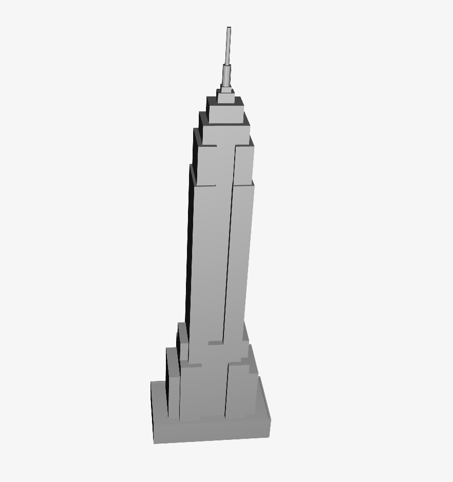
This week we learned how to make composite structures using fiber and epoxy. For this week I initally wanted to make tiny hollow building models with composites. I made the following mode, and its dimensions were 7"*1"*0.6". Tom mentioned that there is no way Shobpot can mill to that level of detail, so I should find other ways of making my buildings.
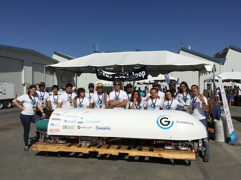
I then recreated my friend Vik's scaled down model of the hyperloop vehicle he made, to get the composites assignment done and learn the process.
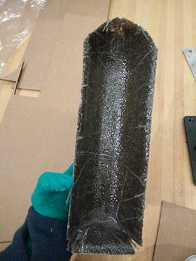
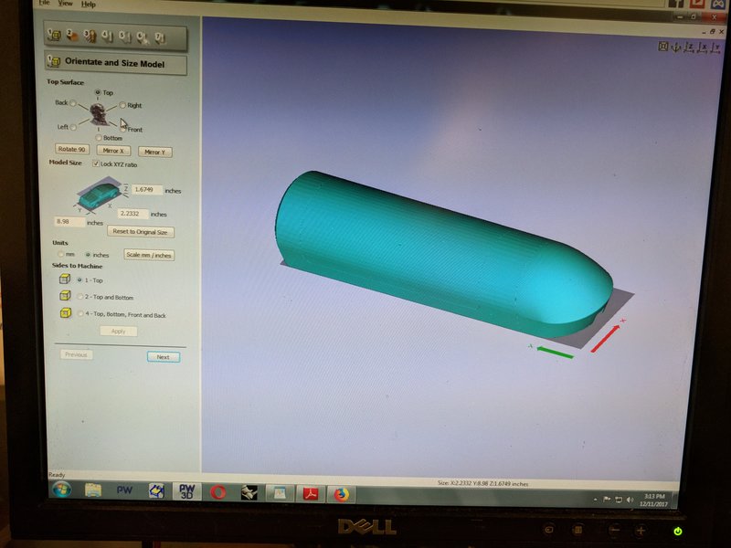
First, we had to mill out the structure we want to make a mold of in the ShopBot. Note the origin is set according to where the Shopbot sees X=0 and Y=0. Add a 0.6in symmetrical buffer around the structure so the ShopBot will mill around the outside.
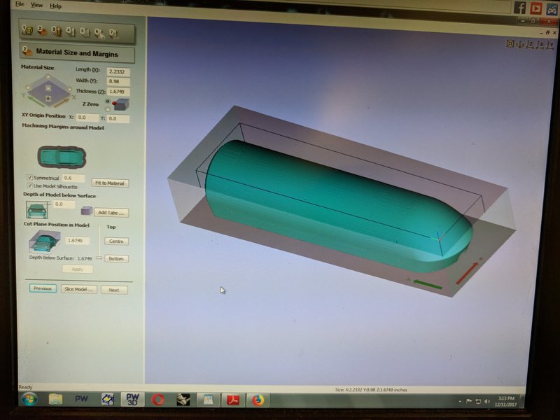
Set the Roughing and Finishing Toolpath with a 0.5in Bull Nose Bit. Raster along Y in this case to reduce the amount the ShopBot has to move. Spindle Speed, Plunge rate, etc are given by the shop instructor.
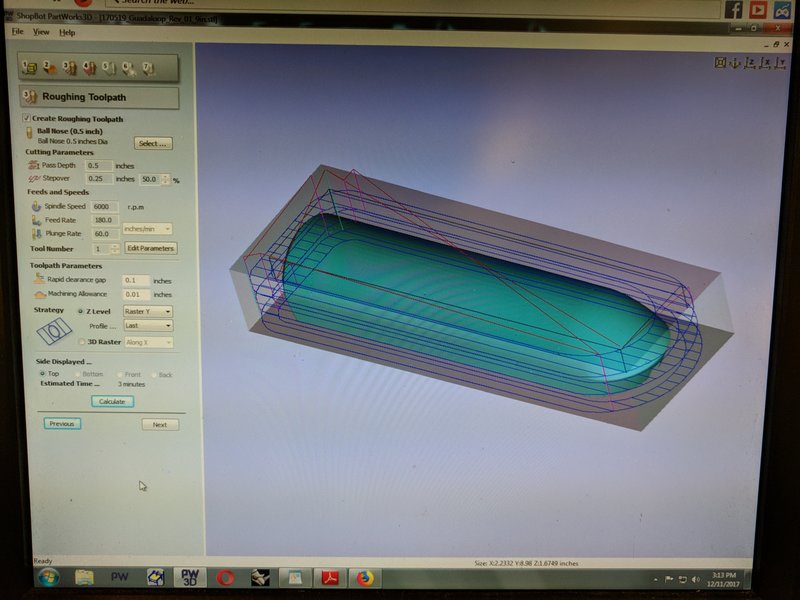
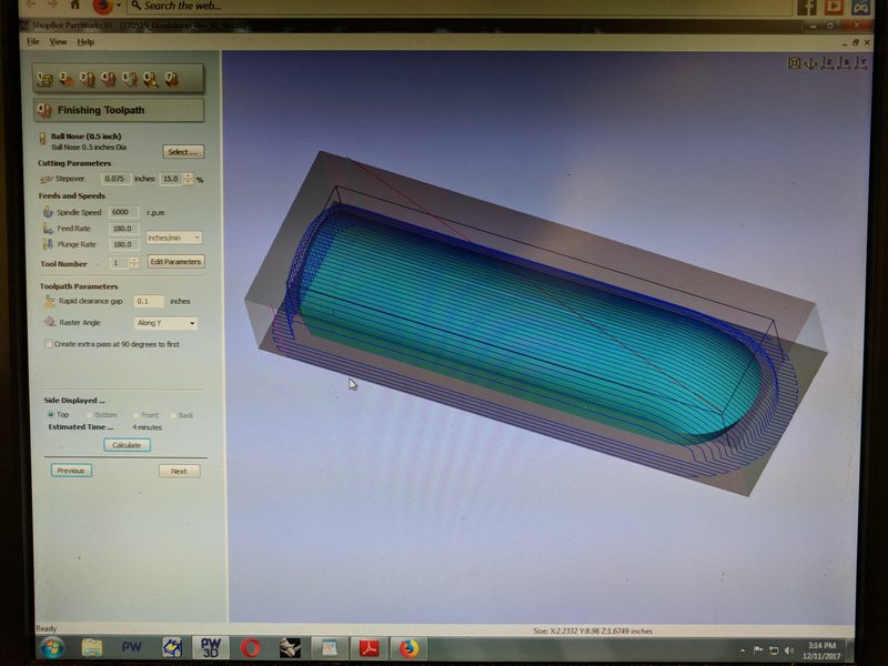
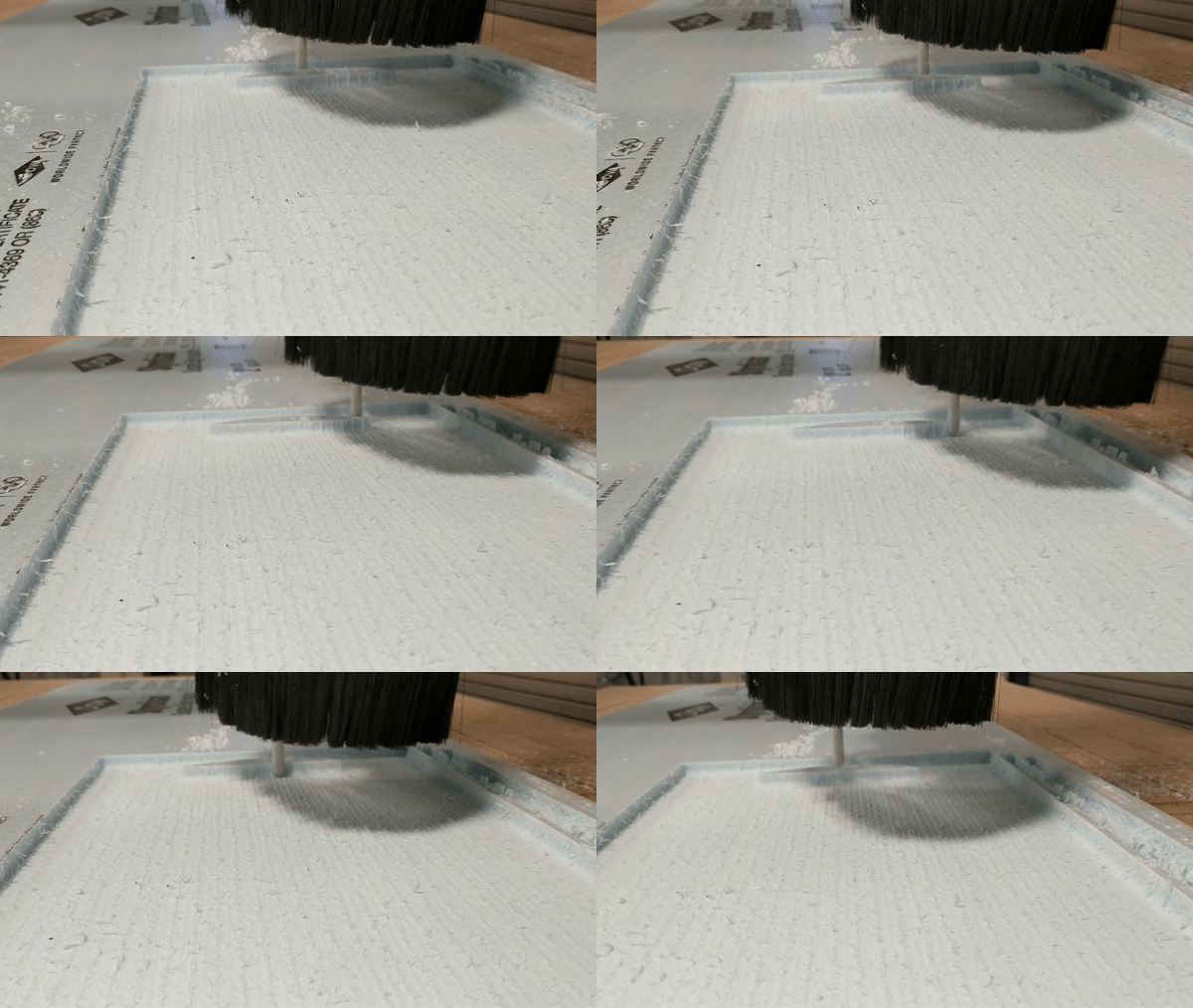
Cut out the mold from styrofoam!
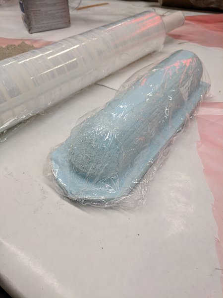
Wrap mold in sticky plastic wrap.
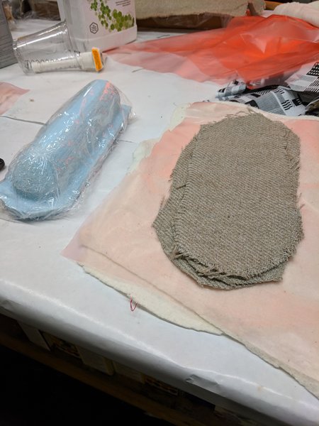
Obtain fabric for epoxy time! Ratio is 100:40 for epoxy mix. After drenching all layers over mold, add a plastic paper (with holes) and a cloth fabric around the entire structure.
Vacuum Form!
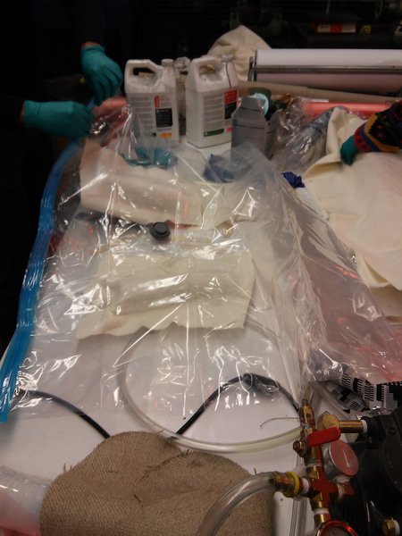
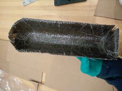
Finally, trim the edges and you're done.

Special thanks to Tom Lutz and Vik for helping me with this week's work. Now onto the final project!
Final Project Idea
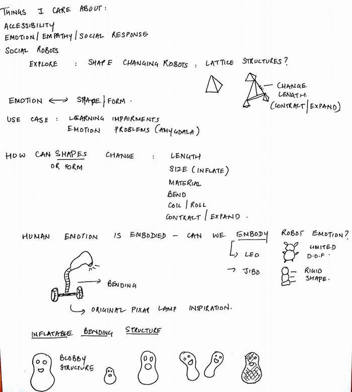
I was overall interested in exploring how emotion can be elicited using shpe changing robotic characters. I want to explore ways in which we can change the shape of a character, and correlate it to embodying emotions in the robot.
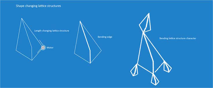

I have started to explore some things in manufacturing shape changers. 3D printing seems like a neat idea. I redid an old jack raise, to explore how we can make it run without falling apart. The exact same mechanism can be used in shapre changing robots, only, we can have a motor that roates the screwn.


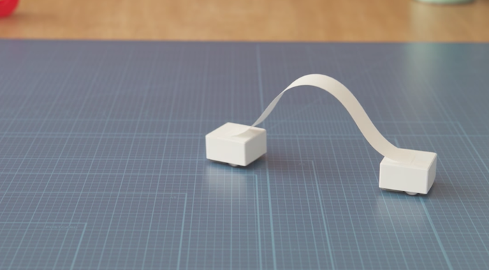
I also got some chance this week to play with Cozmo, and look at Sony's new inventions in simple social robots. I especially likes Sony's blocks, that can use other kind of mateirals (example, paper here, and express a bucnh of things by just moving the blocks.
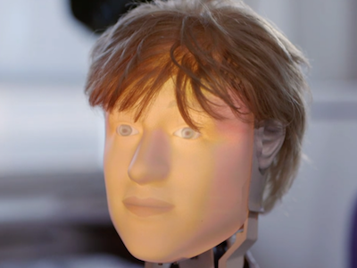
This week I got a chance to attend a molding and casting workshop. I got excited about the possibility of making masks of people, mounting it on a simple motor platform that allows for rotation and use light projection of their faces inside. This might allow me to make actual human like robots low cost. I also found people at Disney Pittsburgh who have been doing this and spent some time looking into their work.
I went back to my initial inclination of working on assistive robots, and am choosing to go slightly tangential to the shape changing idea. I plan to build a movable support for elder care - a support structure that moves to an elder when a fall is detencted. It shoudl be sturdy enough for the elder to hold it and get up. This is an attempt to go a step beyond detecting fall and alerting others.
I came across this work on how we can use a wearable sensor (and make use of the accelerometer) to detect a fall. I can then detect the location of the device, and can drive the structure to that location. The project would involve a. Physical structure building - something that can move + something that can stand sturdy, and b. An accelerometer, on a device, which can talk to this physical structure. Excited.
The project would involve the following sub systems :
I also got interested in being able to make a physical painting machine, where the brushes are all controlled by motors, and based on physiological data, we change brush pressure, types of stroke, and colors used. This would involve getting physiological measures (example, heart rates) and used to those values to control the speed, location, and pressure of the brushes. This could involve a setup with 1 servo and multiple stepper motors.
After the machine design week, where we built the Pancake Making Machine,I am fairly excited about making the emotional painting machine. I looked up a bunch of ways I can have an easier 3 axis machine (like using delta robot). I also looked at a lot of research on aesthetics and vision, which talk about emotions and certain elements within painting such as color, brush strokes, etc. I plan to integrate these two, and make a painting robot that correctly depicts the person's current emotion.
During the last two weeks I went back to all my project ideas, and again got interested in making 3D interactive maps. i thought about laser cutting multiple map layers and casting buildings with embedded lights. I explored various ways of making tiny buildings. Read more in the final project tab.
