Week 6: Embedded Programming
"Priyanka Learns HOW TO MAKE a PCB Do Something!"
For my sixth assignment for How to Make (Almost) Anything, I am going to be making an embedded system where I used my board from two weeks ago to program it to blink the when pushing the button on the board. Throughout this process, I learned to program in C, I learned what a MakeFile and HexFile was, how to create a HexFile from a MakeFile, how to use command line in Terminal, and use a AVR programmer to actually program my board with my code. This was not at all a trivial task for me, as I am extremely new to programming, despite being at MIT for quite some years. Nevertheless, a really exciting and empowering experience!
I was first recommended by TA Mike to start learning the programming language of C by reading (and doing the mini tutorials from) a really useful book on C by Brian Kernighan and Dennis Ritchie (printed in 1988)
Even though learning C was a helpful exercise, I still needed to really understand what it means to do "embedded" programming, where software talks to hardware. The first thing I needed to do was to read the Data Sheet for the microcontroller (ATTiny44A) that I am using. (Throughout this whole process, I really learned just how important reading data sheets are!)
From the datasheet, I came across probably the most useful diagram in the whole document -- a diagram of what each pin on the microcontroller is allowed and capable of doing. Below you can see the pin description diagram for the ATTiny44A.
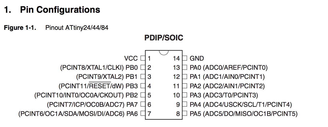
Figure 1: Pin Configuration for the ATtiny 44A Microcontroller
I used this diagram to design and fabricate my board from two weeks ago, but the board is also really useful to determine how to program the board as well. The letter number combinations closest to the pin markings became critical information for me as I progressed in programming my board in C. Knowing which physical components connected to which "PB" or "PA" was absolutely mandatory for me to program my board correctly.
I realized that what I needed to do was to break down what I wanted my board to do into "micro steps" and then program each step line-by-line and to make sure that the pins I am "calling" to do the commands are the ones actually connected to the physical devices that need to either take in information or output it.Throughout my process of programming the board, I came across this very useful website from a former HTMAA student who was also new to programming and embedded systems, yet who documented her process really nicely:
Kelly Shaw's Awesome HTMAA Week 6 Page Link
On Kelly's page, she goes through her process of board design and milling to then using the Arduino environment to program a blinking LED>I took some hints from Kelly, and decided to create a C file where when I pressed the button on the board, it would blink for a second and turn off. I went ahead and first identified which pins on the microcontroller are connected to the LED and the Button. Looking at the datasheet diagram again, I realized that, on my board, the LED was connected to pin PB2 on teh ATTiny44A and the button is connected to PA7. In my code, I will need to call both of these pins.
To do this, I identified two header files --> one from the AVR IO and the other from a Utility macro (which apparently can be shared between several source files).
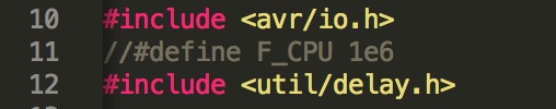
Figure 2: Initializing the Header Files to Use in C File
I then went ahead and initialized the button as an input device and the LED as an output device using the "DDR" register and locating them to be "on" using the "PORT" pin-mapping register.
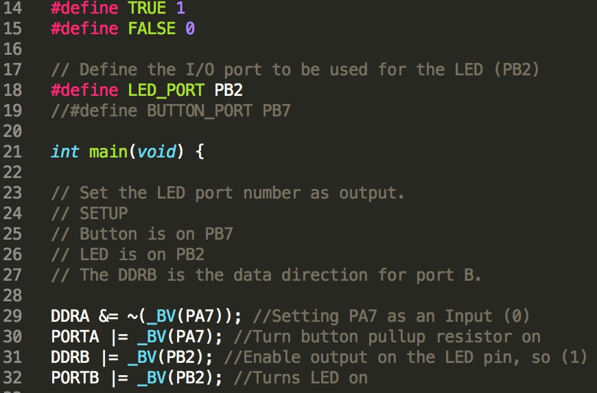
Figure 3: Defining What Pins are being Read and How using Bit Shift Commands
I then finally wrote my C code that actually dictates how the button is to blink. I got some inspiration from Kelly's page and tried it myself!
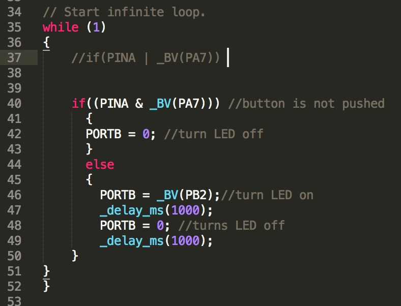
Figure 4: Code for Blinking LED when Button is Pushed
Now that my C file is complete, I then used Neil's makefile to create the HEX file required to send commands from my computer to my board. I then connected an AVR programmer to ran the following commands and see what comes of it:
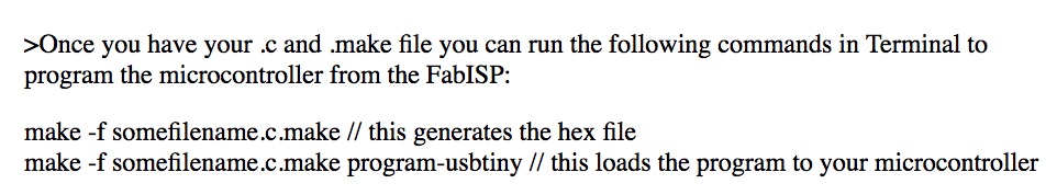
Figure 5: Terminal Commands
After giving it a first try (and the LED actually turned on!!) I nevertheless realized that something was off in the timing. I checked in with my classmate Ben to see what can be done about this and he explained to me how the clock frequencies were off and that the board was using the internal clock from the microcontroller instead of the external one from the resonator that I have soldered onto the board on Pin PB0 & PB1.
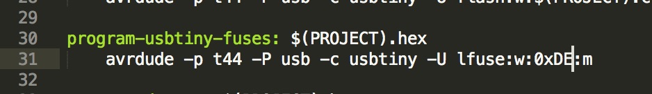
Figure 6: Changing the Fuse Type to DE in Neil's Makefile
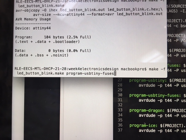
Figure 7: Running the Code with the New Clock Frequency
Now that the frequency that is being used to power the microcontroller is coming from the external resonator, it should work exactly as planned! *crossing fingers*
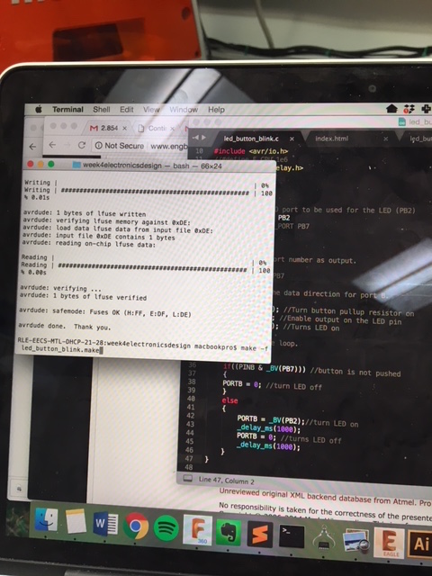
Figure 8: Code Runs Successfully!
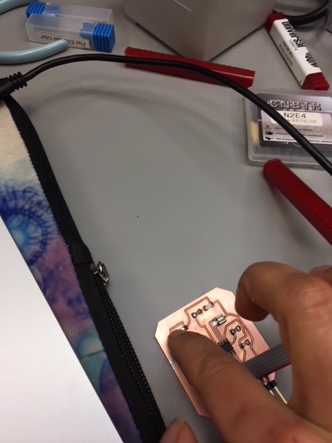
Figure 9: Pressing the button! Dun, dun, dun!
Figure 10: It Works!!
Cheers to my first (and albeit super simple) embedded systems programming project! More excitement on this front to come!