HOW TO MAKE (ALMOST) ANYTHING
MAS.863 / FALL 2011
KELLY SHAW
M.ARCH LEVEL III
03 / PCB DESIGN, FABRICATION, AND ASSEMBLY
04 / WATERJET CUTTER AND CNC MILLING
11 / INTERFACE AND APPLICATION PROGRAMMING
12 / MECHANICAL AND MACHINE DESIGN
13 / NETWORKING AND COMMUNICATIONS
WEEK 07 / EMBEDDED MICROCONTROLLER PROGRAMMING
This week we programed an ATtiny44 microcontroller using the FabISP Programmer we
created from Week 03. We were asked to add a push button and LED to a modified PCB
layout from Eagle.
01. Designing the PCB
We used Eagle to add our button and a LED to the schematic. I missed the tutorial but Neil
was nice enough to take some notes which I've included here. I found that the best way to
learn the UI for Eagle was to look at some existing schematics from previous years and
try to replicate them, while switching to the layout view to better understand how the traces
and components are laid out.
[schematic view]
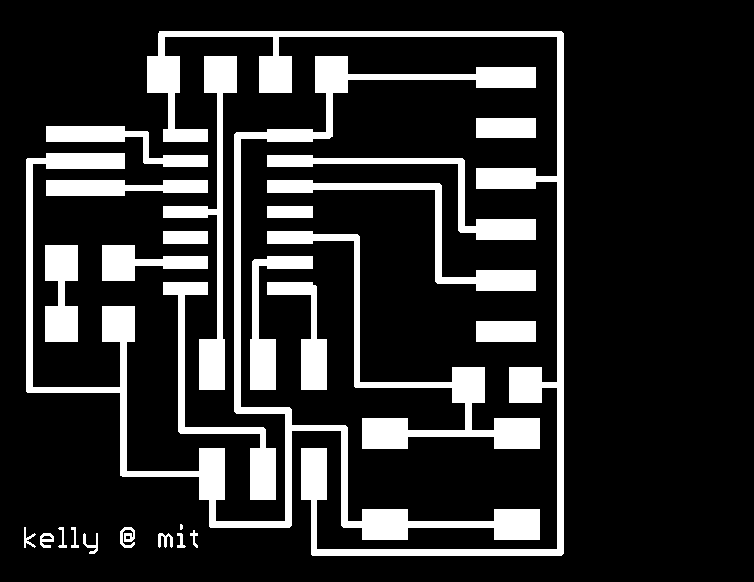
[exported .png of traces from layout view]
02. Milling and Stuffing the PCB
I used the default settings for a 1/64'' bit for milling the traces. For the depth of cut, the default
value was 0.1 mm but after one pass, my traces appeared to only be partially milled.
[partially cut copper traces]
On the second attempt I successfully re-cut my traces with a depth of 0.2 mm. To do the cut-
out with the 1/32'' bit you have to remember to double check the 3D settings. The min Z-cut
should be 0 mm, but the maximum depth of cut should be about -1.8 mm to ensure you cut
completely through the board. The Z-step should be at 0.5 mm.
[milled board]Stuffing the boards was pretty straight forward but it was important to check the orientation of
the LED and the ATtiny44 microcontroller. On my first attempt I had soldered my LED in the
wrong direction. The green line on the LED should be pointing away from the resistor and
the resistor should be limiting the current going into the LED. I was able to check if my LED
was working properly by using the FTDI cable and running the Blink program example from
Arduino.
David Mellis ran a good session on programming the ATtiny with Arduino and most of the
steps can be found on the high-low tech site.
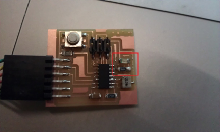
[problem area on fabricated board]
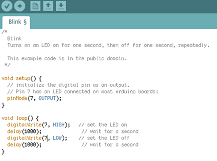
I edited the Blink.c example to work for my board. In my case, the LED was located on Pin 6,
which in the Arduino environment referred to Pin 7.
[Arduino Blink example]
[LED working]
03. Programming the ATtiny44 in C
Programming the board to turn the LED on when the button was pushed seemed like an easy
task in theory...until I realized that I didn't know much about C libraries, bits, bytes, registers, the
difference between WinAVR and CrossPack , or what a .c, .make. or .hex file was.
The debugging session David held became my opportunity to ask as many questions as possible
and here's what I learned [thanks David!]:> It's good to understand the syntax for the language. Some good places for understanding
the basics include:AVR Libc
HLT Wiki
> The .c, .make, and .hex business. The code you write is saved as a .c file. I used TextEditor
to write and edit my code. With the .c file you need to create a .make, file which includes a
compilation of program commands that translate your code (.c files) into machine code
(.hex files) for the microcontroller.
>Once you have your .c and .make file you can run the following commands in Terminal to
program the microcontroller from the FabISP:make -f somefilename.c.make // this generates the hex file
make -f somefilename.c.make program-usbtiny // this loads the program to your microcontroller
My steps to learning how to program in C included getting the LED to turn on, getting it to blink,
getting the button to control the LED, and finally getting the LED to turn on and stay blinking
when the button was pressed. Here's the final code:
// LED Button Blink Program
#include <avr/io.h>
#define F_CPU 1e6
#include <avr/delay.h>#define TRUE 1
#define FALSE 0int main()
{
//SETUP
//Button is on PA3
//LED is PA7PORTA= _BV(PA3); //Turn button pullup resistor on
DDRA = _BV(PA7); //Enable output on the LED pin
PORTA = _BV(PA7); //Turns LED on//LOOP
while (TRUE)
{
if ((PINA & _BV(PA3))) //button is not pushed
{
PORTA = 0; //turn LED off
}
else
{
PORTA = _BV(PA7); //turn LED on
_delay_ms(1000);
PORTA = 0;
_delay_ms(1000);
}
}
}
[FabISP programming the ATtiny44]To see everything in action:
LED BLINKY BUTTON VIDEO