The Plan
The plan this week was to play around with computer controlled cutting machines, namely the laser cutters and vinyl cutter. For the laser cutter, we were tasked to create a press-fit construction kit that contained parts that could be assembled in multiple ways. Immediately my mind went to geometric shapes and polyhera. What's awesome about regular polygons is that they act as fundamental building blocks of our own world, and coincidentally, also the world of CAD (computer aided design). So for this project I started with desiging the pieces I would need to construct an icosahedron, knowing that if the building blocks were designed properly (read: parametrically), then I could make simple modifications to expand the designs to different polygons and connectors of different angles.
For the vinyl cutter, I wanted to create a personal logo of sorts that symbolized me, and then cut that our of vinyl to create a personal sticker for my laptop.
Laser Cutting - Group Project
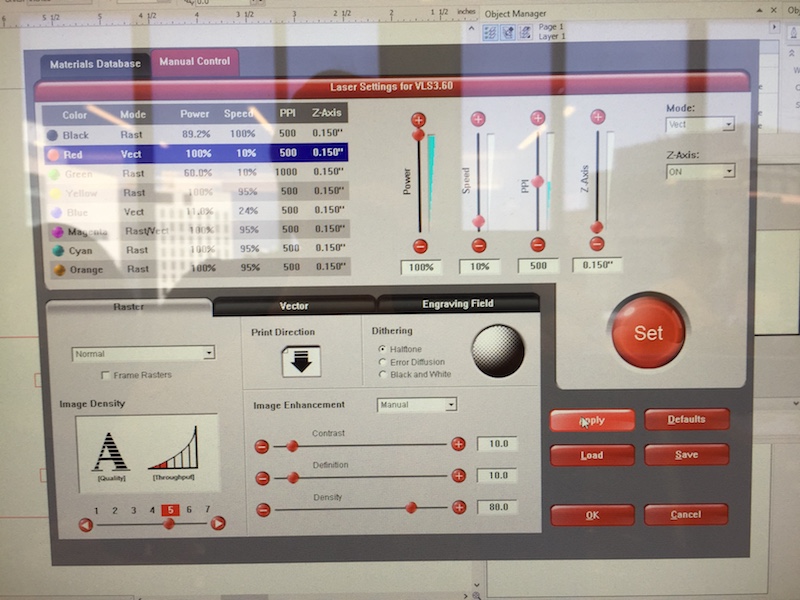
As a group (or subgroup) in the EECS lab, we started our adventures laser cutting cardboard by first gaining a better understanding of the different setting in the laser cutter. Properly laser cutting a material means finding the right balance of speed and power to cut, engrave, or raster your material. Additionally, since we were all creating press-fit kits, finding a reasonable joint mechanism (using chamfers) and finding the best widths for the slots (to deal with kerfing) was really important.
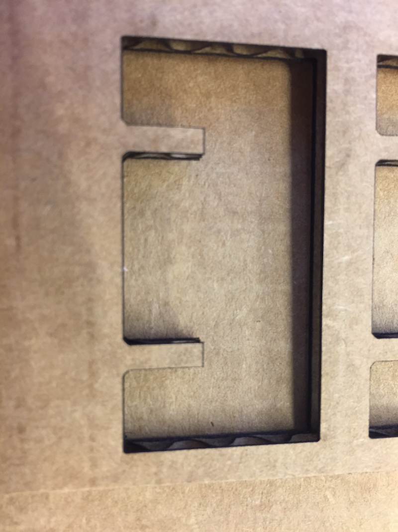
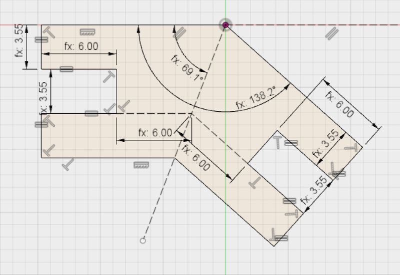
The first step in testing the laser cutter is to have a design. After looking at the joint picture shown in class, I felt like modeling a simple press-fit joint with chamfers would be a great start. In fusion 360, I wanted to create a simple slot with 3.5mm gap with a 0.5mm chamfer.
* Note: If you're interested in learning how to use Fusion 360, check out the resources section at the bottom of this page and at the bottom of my Week 1 page
To start off, I created a sketch will all the dimensions I wanted for the slot. Adding a dimension to a side or angle will start to contrain the sketch and prevent the user from freely moving it. While dimensions can be added manually (for example, saying 3.5mm everywhere I have a slot), a much better design practice is to use user-defined parameters. This is the key concept that makes parametric design and programs like Fusion 360 so powerful. Essentially, instead of saying 3.5mm multiple times in my sketch, I define a parameter called "thickness" that is 3.5mm. Then, everywhere I want the sketch to be 3.5mm I just put "thickness." Now at this point, that might seem like extra work, but if we cut this slot out and realize it's too tight or too loose, then all we have to do is modify "thickness" to a new value, and all instances of "thickness" will update and propogate through the component I'm making.
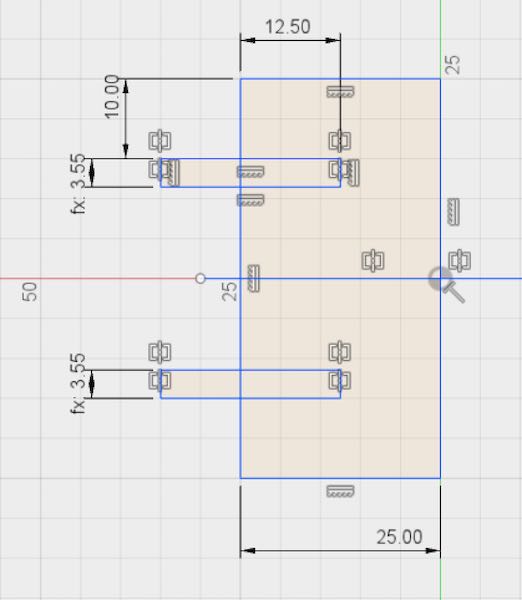
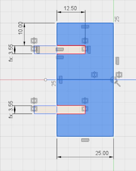
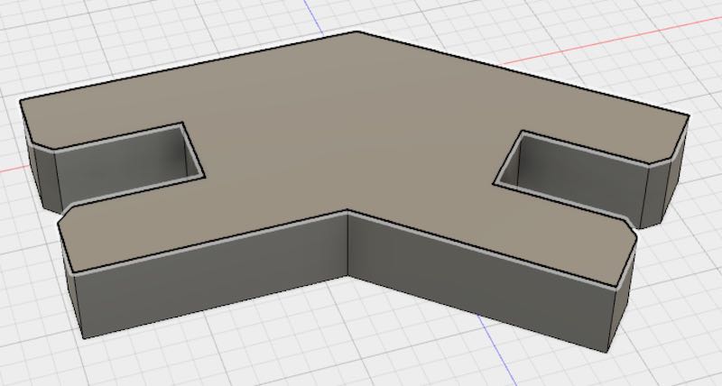
When the sketch is lookin' good, we exit sketch mode, and extrude the highlighted part of our sketch out to a distance "thickness." This looks like the following:
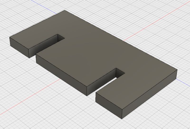
Adding in the 0.5mm chamfer to the edges where slots would slide into each other made the end object look like so:
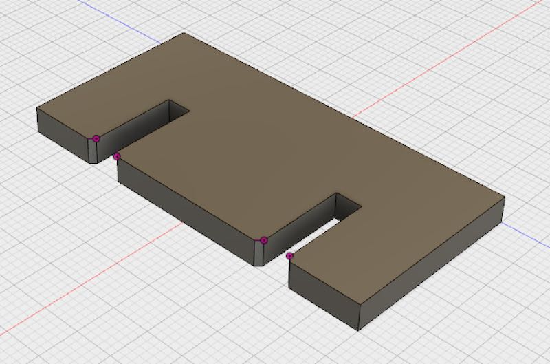
Now originally I was very confused as to why anyone would want to model an object in 3D for something they'd end up cutting in 2D. With some previous experience using a laser cutter, I knew they took 2D vector files like .pdfs, .ai, and .dxf. This is still true, and in fact you do have to essentially extract the 2D sketches that you'll be using to laser cut out of your final component. Thankfully, this is as easy as clicking "Create New Sketch" and clicking on the face of the edge I want to cut. Then I can right click on that sketch and "Export As DXF."
The benefit of modeling it in a program like Fusion 360 as opposed to Adobe Illustrator or some other 2D vector drawing program is twofold: 1) You can use all the sexy parametric modeling techniques to be able to quickly and easily modify designs later on. 2) You do get a much better sense of what your structure will actually look like in 3D after you cut out the pieces and assemble. (Granted, this little edge piece is relatively simple, but if you had multiple components with extrusions in multiple dimentions, modeling this in 3D is super helpful)
Now, let's cut this slot out! I used a universal laser cutter that comes with fairly easy to use software that allows oneself to manually set speed and power parameters for the laser, or choose from a list of presets based on the type of material and thickness. Sending a job to a laser cutter is about as easy as printing out a picture, but with the additional step of modifying the "Print Preferences" before hitting go. Once the preferences are set, you can do your last-minute checks.
Last minute checks include things like:
- Focus the Laser: to focus a laser cutter, there's a little tool that essentially helps you move the laser to a particular distance above your material.
- Make sure the air vents are open: this is critical to keep any gasses produced by melting your material from building up inside the laser cutter.
- Make sure your compressor is on: the compressor is important because it helps more forcefully remove gasses and also debree created around the laser's focal point. For cardboard, this make the difference between the cardboard catching of fire, and it being alright (maybe).
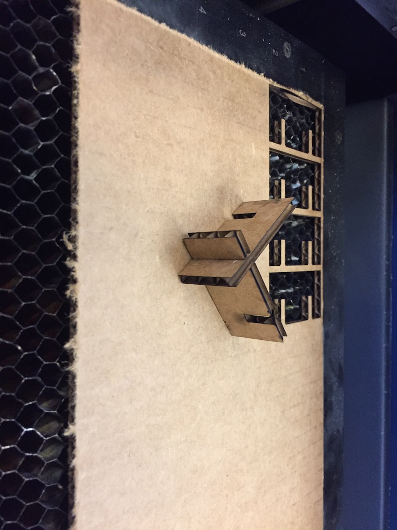
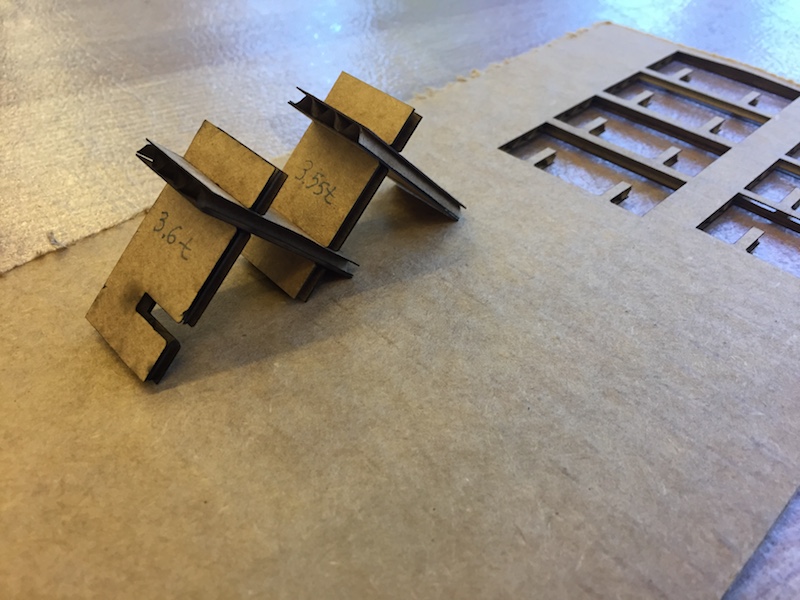
Now if you were paying extreme attention, you probably realize that the slot space in the sketch above is 3.55mm and not 3.5mm. This is because the above pictures are from the final settings I had (now I know to document and take pictures / screenshots as I work). At any rate, the original 3.5mm was fairly tight, and pushing the slots together worked but required a fair amount of force. So I cut additional slots with 3.55mm and 3.6mm thicknesses, and also increased the chamfer to 0.7mm to help the slots slide together more easily.
Overall, I found that 3.55mm slot and 0.7mm chamfer worked best for this type of slot. It still required force to push the slots together, but the connection was pretty solid. Additionally, I used the following settings for the 60 Watt Universal Laser Cutter: 100% speed, 10% speed, and a material thickness of 1.50 inches. (Note that 1.5 inches is a larger thickness than our slot. This is purposeful. We had to model our thickness in our CAD program to be smaller because of laser kerf. This essentailly means that the laser will take away more material due to the thickness of the laser beam, and that has to be reflected in the design)
Laser Cutting - Self Project
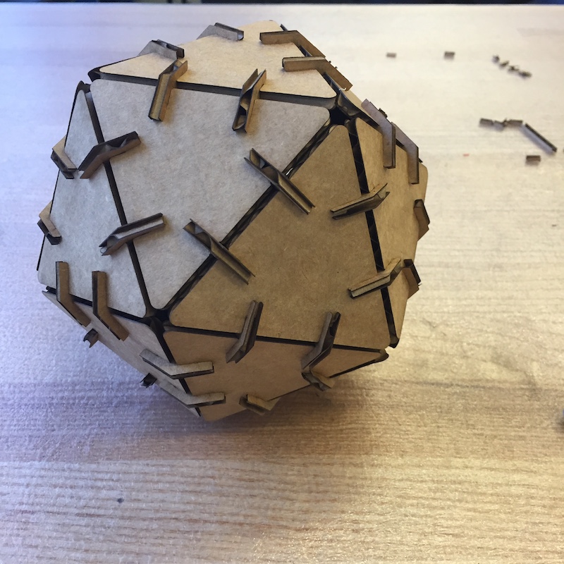
So I love simple geometric shapes. They appeal to me for two major reasons: 1) They are extremely simple and elegant and carry with them a sense of minimalism. 2) They are the fundamental building blocks of more complex shapes and structures. This is why I chose to make an icosahedron for my personal project of the week.
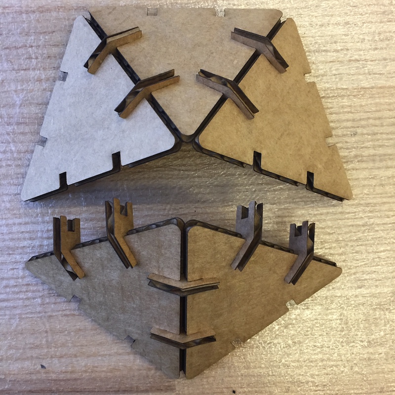
Icosahedrons are composed of 20 faces of equilateral triangles fit together at certain offset angles from each other. My approach to designing this structure was essentailly to cut out faces of the icosahedron with 2 slots per edge of the face. The slots would be very similar to the mechanism we tested in our group project. Then, smaller connector pieces of cardboard would slide in orthogonally to the face, and would have a bend in them that would allow faces to connect to one another at the correct offset angle.
Below are the sketches for the triangle faces with slots in the side. This slot sketch was adapted from the group project, and it was mirrored over lines of symmatry for the equilateral triangle to provide radial symmatry for the triangle faces.
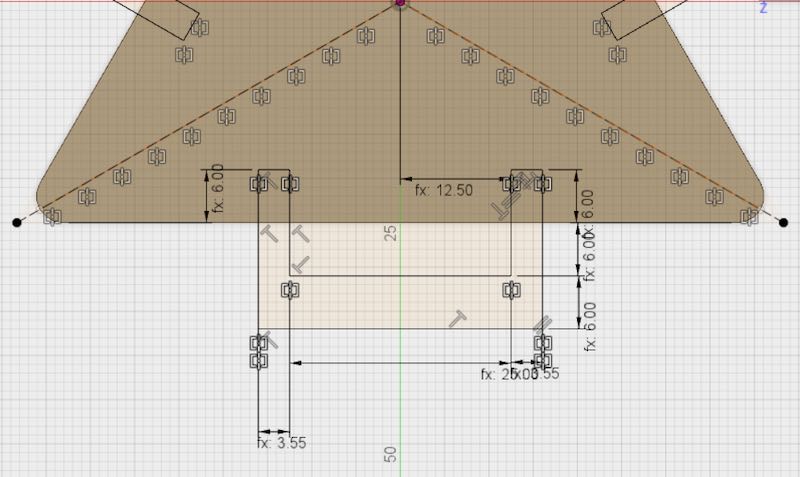

Extruding that out and adding appropriate 0.7mm chamfers resulted in a component that looks like this:
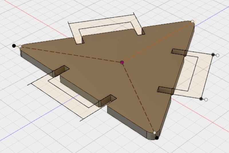
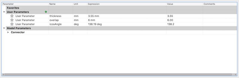
The next step was creating the connector that would fit between edges. I wanted the edges to fit snugly with each other, so the connector was engineered with lots of constraints to ensure this. The overlap, thickness, and bend angle had to be correct. I got the correct bend angle from this wiki page. Using parametric design in this connector was also crucial because proper parametric design here would allow me to quickly create connectors for many different types of polyhedra with different bend angles. Below are the parameters, the sketch, and the model for the connector:
Cutting several of the triangles and connectors out allowed me to test the fit before I cut out all the sides.

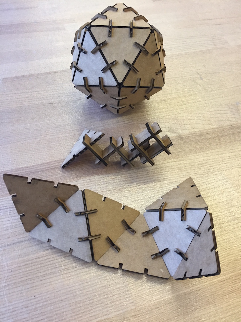
The fit was really solid! The most difficult part in the construction was fitting one traingle into the final slot in a 5-traingle icosahedron cap. The angle of insertion of the pieces was almost perpendicular to the angle the connectors slid into place, so a lot of squeezing and forcefullness was necessary to put in this last pice in the puzzle:
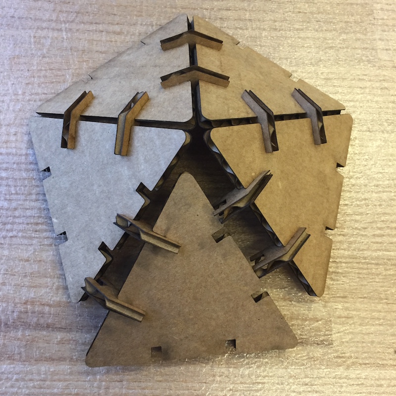
However, I realized that if I put a 2 triangle module into a 3 traingle module to create the 5 triangle cap, the insertion angle was almost perfectly alinged with how the connectors slid into place. This made for a much better building process and less forcefull insertions:
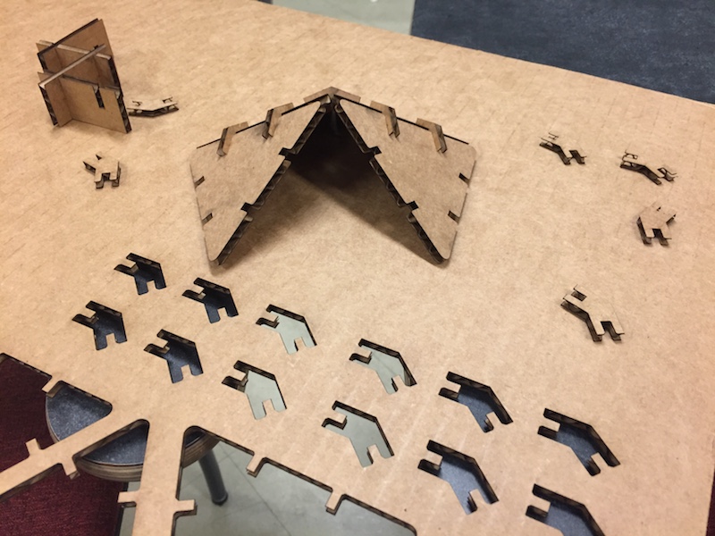
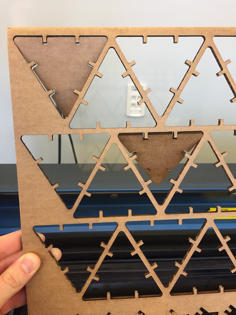
With that building mechanism ready, I was confident I could scale out from 5 traingles to the 20 traingles needed to create the whole structure. After a little extra copy-paste, I cut out a bunch more traingles and a lot more connectors:
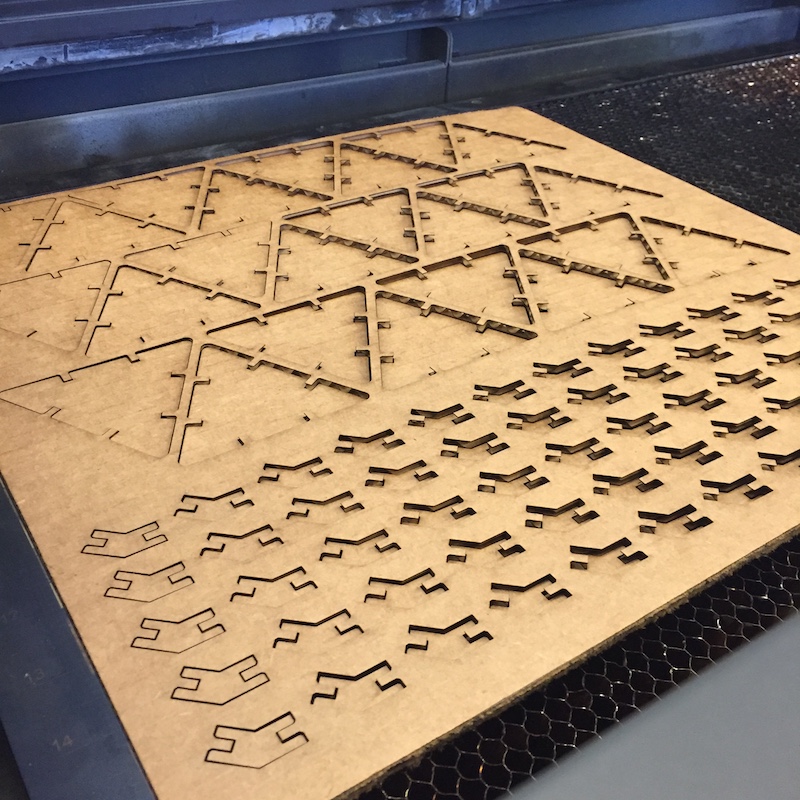
Sadly, some of the triangles and connectors didn't cut all the way through... This was ok because I actually cut out more than the necessary 20 triangles and 60 connectors, however I knew almost immediately why not all the shapes cut through. Looking back at the image above of all the triangles and connectors laying on the laser cutter bed, you might notice that some of the pieces in the center look like they've fallen through more than the ones toward the edges. This was actually a product of the warping of the cardboard. Because the pieces of cardboard weren't completely flat, I had focused the laser to cut properly in the middle of the sheet of cardboard. However, the traingles and connectors toward the edges of the cardboard were lower down on the bed, and subsequently farther away from the laser than the pieces in the middle. This caused the laser to be less focused on those pieces, and thus wasn't able to cut all the way through. This was a good learning expereince because with cheaper materials or materials that aren't "kept well," they may start to bow and warp (just like how wood warps a lot if left outside or in the rain).
With enough pieces to finish my icosahedron, it was mostly just a process of fitting things together. This felt very meditative and was actaully deeply satisfying to watch the whole icosahedron form over time.
Vinyl Cutting
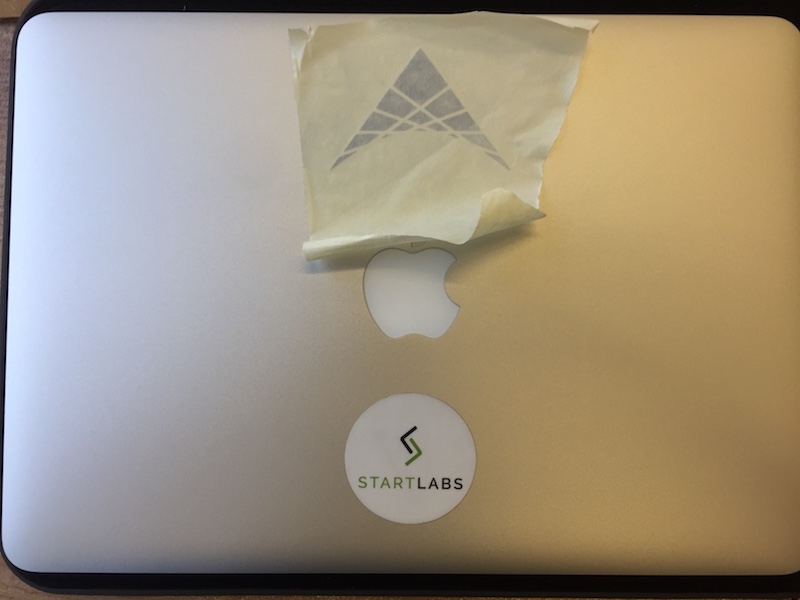
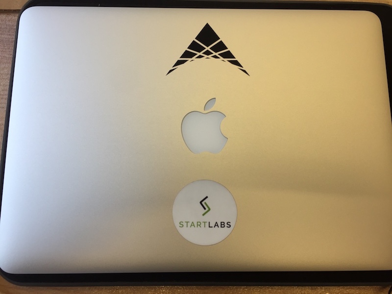
Our second personal task was to create a sticker using the vinyl cutter. Having come up with a personal logo of sorts and made laser-cut wooden business cards the week prior for a different class, I was content with using the same design as the basis for my sticker:

The design itself is one fifth of a start (if you copy and rotate 72 degrees a bunch of times). It also has a bunch of lines going through it which is a design style I played with a lot as a kid. I was constantly intruiged by how I could approximate a curve by adding a bunch of lines slightly askew to each other. The reason the design is one fifth of a start is because of a brainstorming session I had over the summer to help categorize the important areas of interest in my life: Technology, Business, Design, Language, and Global Exploration. While I don't necessarily devote equal time and energy into all the areas, each area is undoubtably an important part of my life. Additioanlly, one fifth of a start oriented as I do below kind of looks like an "A," and my last name is Allen. So I thought it looked pretty good.
The laser cutter I used was run on (open source?) software created by the professor of this course, Neil Gershenfeld, along with the help of various teaching assistants. It's called mods, and runs on a local server that is connected to the vinyl cutter.
The software would take in a png file and do some image processing to extract the edges of objects in the picture, and use those edges as cutting lines for the vinyl cutter. The deptch of cut and origin of design were could set on the vinyl cutter itself. When ready, I pressed "send file to printer."
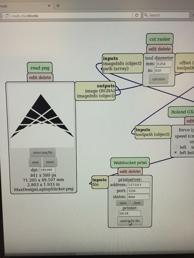
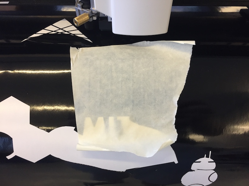
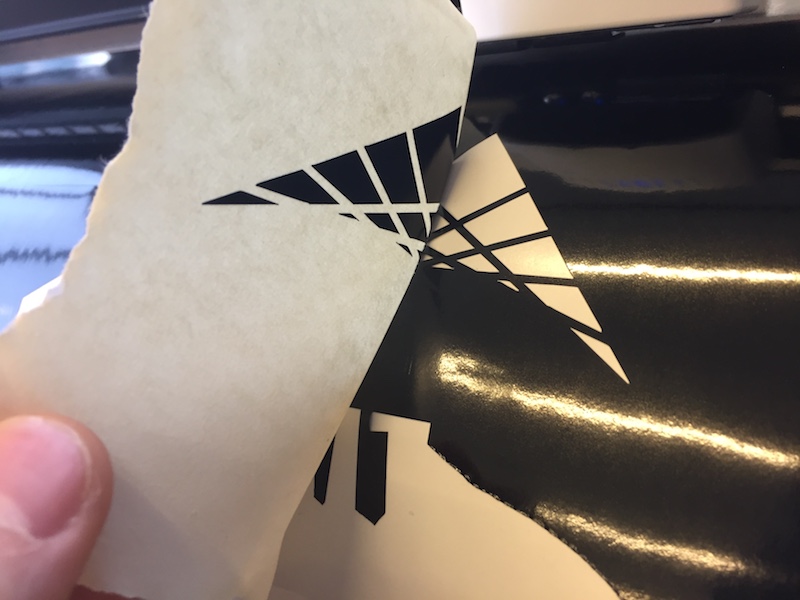
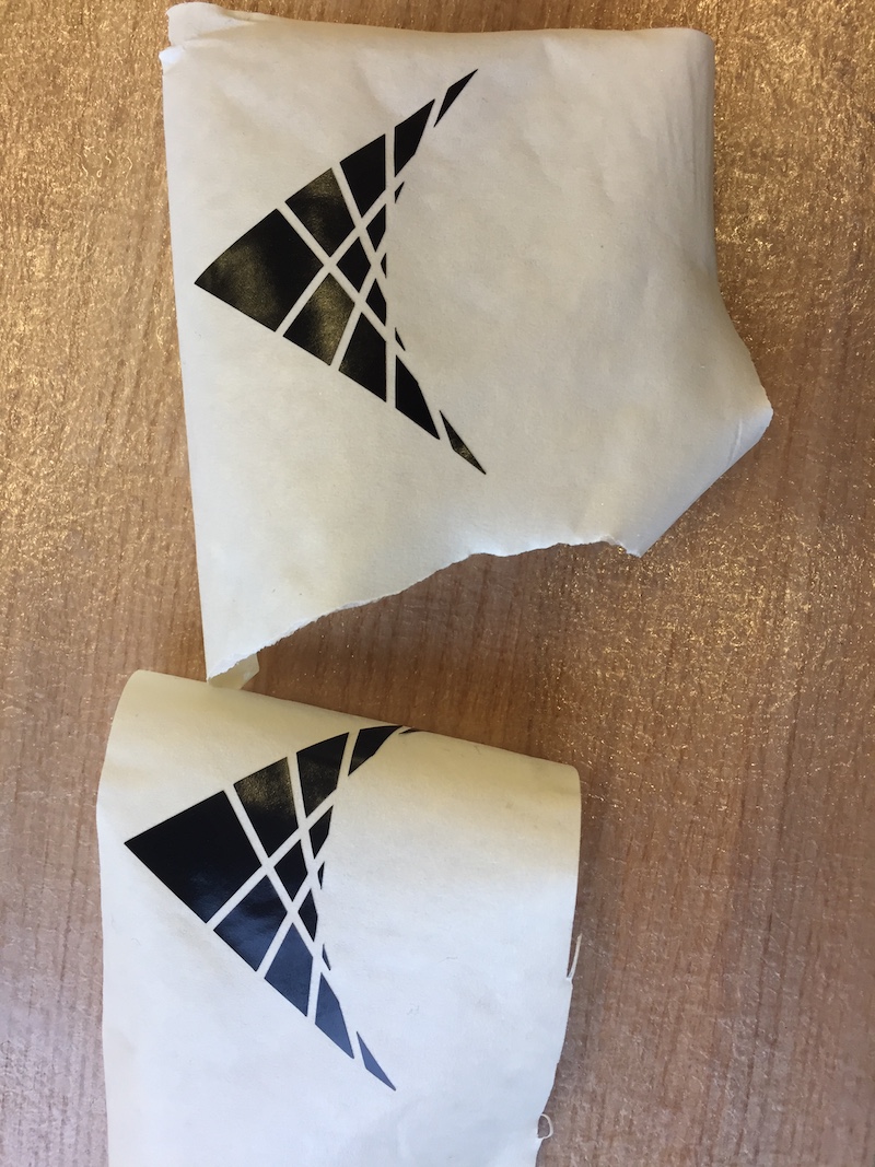
Since my sticker is composed of many smaller pices equally spaced apart, I had to use tranfer tape to first tranfer the components of the design onto tape, and then was finally able to stick that tape onto my computer and cafully remove it, leaving the final sticker. An important thing to mention is that it's important that the vinyl cutter cut deep enough to remove the actual vinyl, and if using tranfer tape - I would suggest using a gift card or some other type of card to swipe over the vinyl to make sure all the components of the design are picked up.
Really cool!
Terminology
Chamfer, Kerf, Polyhedra, Dihedral Angle, Parametric Design
Technologies Used
Autodesk Fusion 360, Adobe Illustrator, CorelDraw, Laser Cutter, Vinyl Cutter
Resources Used
Parametric Design in Fusion 360
Dihegral Angles of Polyhedra