Computer Controlled Machining
Computer Controlled Machining is somewhat of a superset of Computer Controlled Cutting that isn't limited to just cutting material. This includes classes of machines including multi-axis milling machines and CNC routers, which we used this past week.
The complexities of using these types of machines are different than the cutting machines. With most cutting machines, there's typically a 2D surface and a thin line (or vector) of material that you're trying to cut through. With routing, instead of a laser going straight through all the material, a milling bit both drills into the material, and routes horizontally through material. This means that the path of the actual drill bit becomes extremely important when properly manufacturing the part. There are parallel complexities in cutting such as focus and kerf, but thorough understanding of those isn't necessary to making basic parts.
Making Something Big
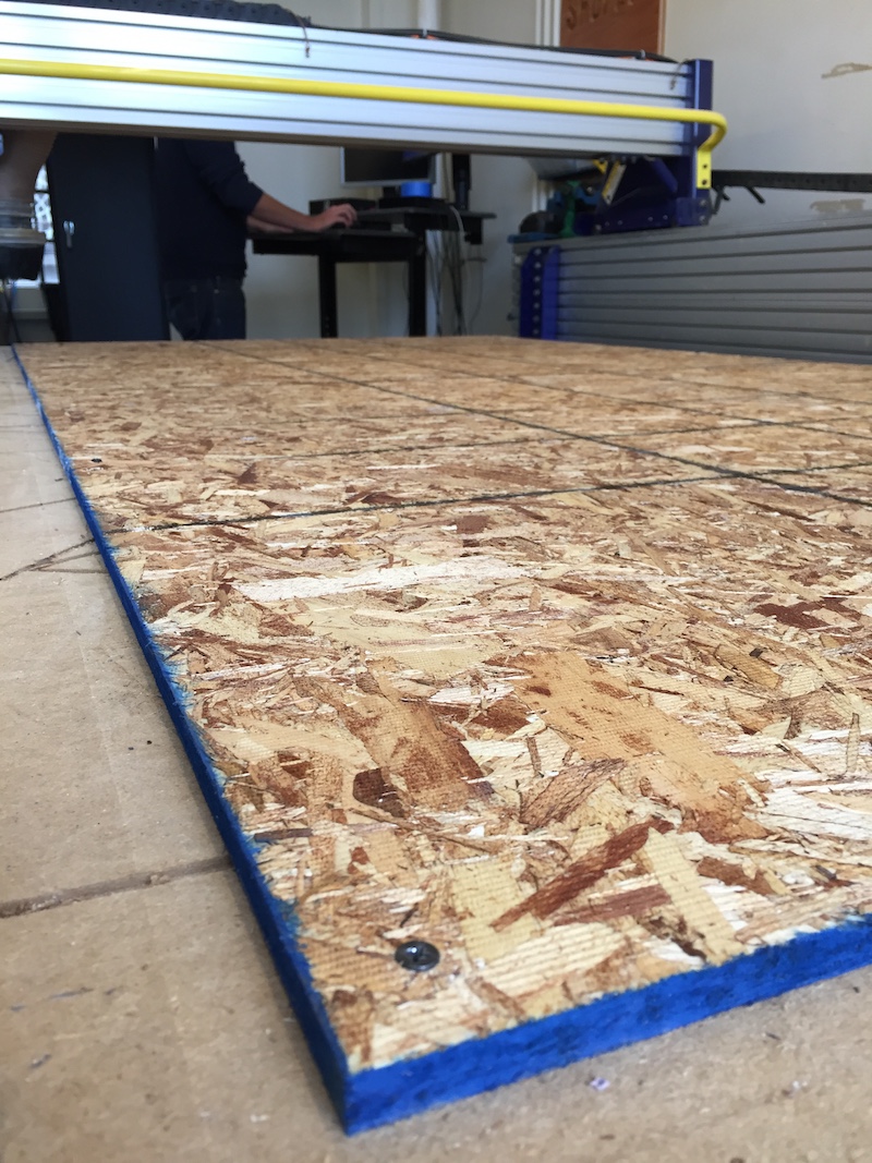
The task of the week was to make something big. Specifically, make something big on the Shopbot Router out of a piece of 4 foot by 8 foot OSB board. What is OSB? This is OSB:

It's the salami of wood.

Basically, it isn't terribly structural, and splinters extremely easily (because it's basically made up of splintered wood), but it's really cheap. The whole 4 foot by 7 foot piece can cost the average consumer around $15-20 at your local Home Depot. Nice wood is expensive, and can cost an order of magnitude or two more than the OSB for the same dimensions.
My project for this week was to build a Marquee sign, similar to the type you see over old theaters:

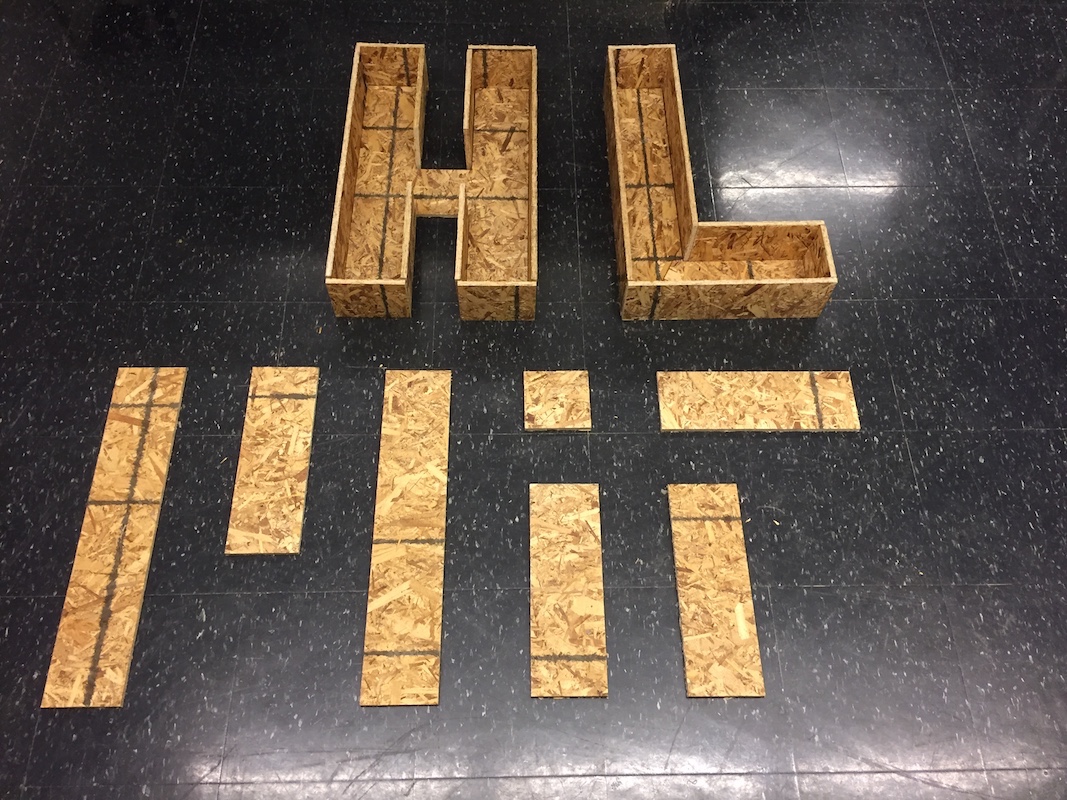
My close friend is the proprietor of a hotel called Hotel Lebron, so I thought I'd make him a sign that reads "HL". At first I wasn't sure what sign to do, so I sketched out a bunch including "MIT" and "HTMAA".
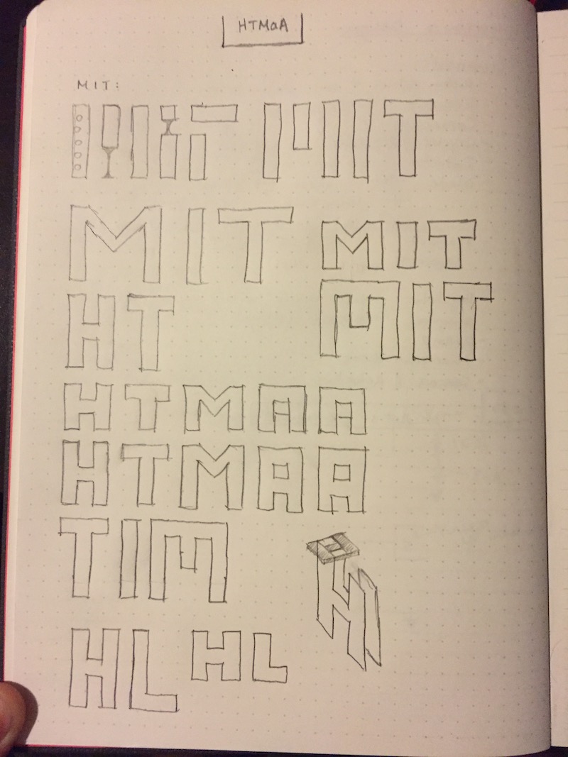
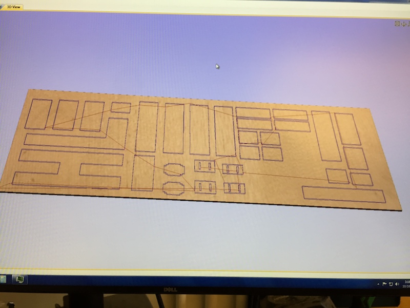
These were all relatively simple shapes to draw in CAD (all could be drawn on a 5x5 grid), so I mocked up the parts in Fusion 360.

The plan was for "HL" to be surrounded by a wooden frame, and MIT to be surrounded by galvanized flashing. Additionally, I was curious about how press-fit could work with the OSB, so I created an additional shape the size of the dot in the "i" of "Mit." I kept both the thickness of the wood (.5") and the thickness of the letters (5") as parameters.
I was running into a lot of troubles with Autodesk 360 slowing down, having trouble copying and pasting, and crashing over and over when trying to zoom out. While there is an autosave feature in Autodesk 360, I would encourage everyone to SAVE OFTEN! It's a huge pain to redo work again and again due to multiple crashes.
The hallmark of this week was working with the Shopbot.
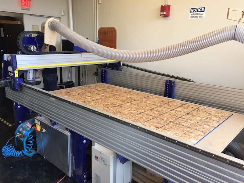
This is a monster of a machine and not something to play around with without proper safety and usage training.
The first step in Getting your design cut out on the Shopbot is to fasten your work to the sacrificial layer of the Shopbot. To do this, we just added wood screws right through the boarder of our board. Before you do this you want to make sure the wood is paralell with the sides of the Shopbot. I just used a ruler to do this.
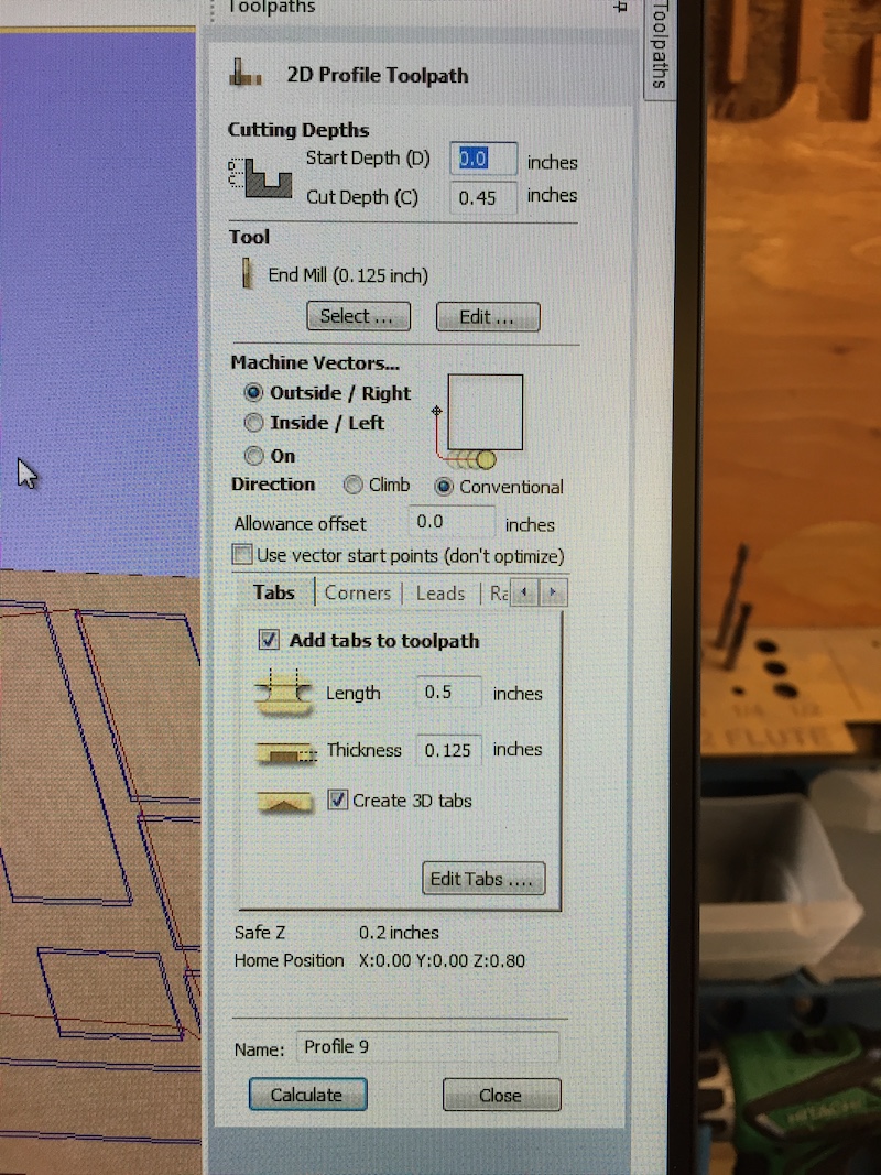
Next we took our 2D vector file (DXF, AI, etc) and imported it into the routing software, VCarve. VCarve essentially allows you to create tool path profiles for groups of vectors. These profiles include things such as how deep you want to cut, whether or not you want to add tabs, and specify what size end mill you're using.
Most of this was fairly repetative, and having someone there who had been through the process made setup a lot easier. The flow of the software was new to me, but I'm sure most Computer Aided Manufacturing (CAM) software goes similarly to this. It's mostly a matter of having the institutional knowledge of how to use the particular software.
There were still two things that went wrong for me during all this setup. The first thing was orientation of my DXF file. When I first imported the design, it was in portrait orientation. I realized when I went to make my air cuts that the router thought the origin of the bed was actually somewhere far off the bed. To fix this, I had to create a new VCarve canvas, copy my design, rotate it, and then move it to the proper landscape-oriented canvas. The second thing I did wrong was I had also imported a 4 foot by 8 foot rectangle that was there as a result of how I set up my Fusion 360 file. This was basically an outline of my actual board, but since it was the size of the canvas, I didn't realize it was there until trying to do more air cuts. The fix to this was just to delete the vector path in VCarve and recalculate tool paths.
Once the tool path profiles are all good, there are a couple important steps to follow:
- Insert the endmill if not already inserted. Tighten the end mill as much as you can. If the end mill comes lose during actuall cutting, this can cause serious danger.
- Make sure every part of the router is on ~ including the axis motor controllers, the end mill, and all necessary ventalation systems.
- Do air cuts. These are where you zero the Z-axis of the machine much higher off the bed than your actual material. This way you can run the cutting profiles and watch where the router goes and see if it corresponds with what you expect.
- Properlly zero the router. This is fairly crucial and typically involves the bit bouncing off of a metal plate of defined width. This is really important to get right because if zeroed improperlly, the end mill could dive deep into the material, breaking the bit, ruining the sacrificial layer, and also possibly damaging the machine.
Safety with these machines is a big deal. While this is generally true of machines in workshops, the Shopbot is both extremely powerful and not enclosed. If you reach your hand where it's not supposed to be, or if any material catches on the end mill and gets flung across the room, bad things can happen, and people can get hurt.
After doing my air cuts and fixed the problems I referred to earlier, it was time to cut. Cuts of shapes should happen inside-out. What this means is that if you're cutting out two concentric circles, the inside circle should be cut before the outter circle. This is because if the outside circle was cut first, the wood would be loose and could move around during the inside cut. Best case scenario the wood moves a little and the cut just cuts in the wrong place. Worst case the interior circle shape gets caught on the end mill and starts spinning, possibly creating a projectile. So do your cuts inside-out. This can be controlled by the order in which you execute your tool path profiles.
An additional layer of protection is to add tabs to your toolpath. Tabs are basiaclly a setting within CAM that prevents the router from cutting all of the last layer of the model. The router will cut almost all of the last layer out, but will leave 1 or 2 inch lengths of wood to keep the outline of an object connected to the rest of the board. This prevents the object from moving while the router is still running, and the tabs can be easily removed after all the cutting is done with a bandsaw or chisel or just by pushing your object out of the wood like you might break a perforated object out. Tabs are basiaclly perforation for larger scale routing.
Next I did my outer cuts.
Note that the time duration of your cutting process is roughly linear with the sum of the magnitudes all your vectors. So if you're cutting out a large fractal shape with a large perimiter, then expect the cutting to take a while.
After cutting, teardown involves unscrewing the wood from the sacrificail layer, vacuuming sawdust produced by the Shopbot, and moving the wood out of the space.
When institutional knowledge isn't quite right
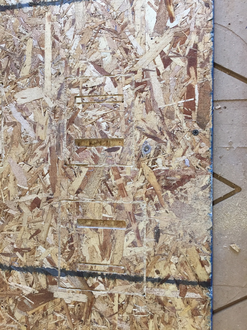
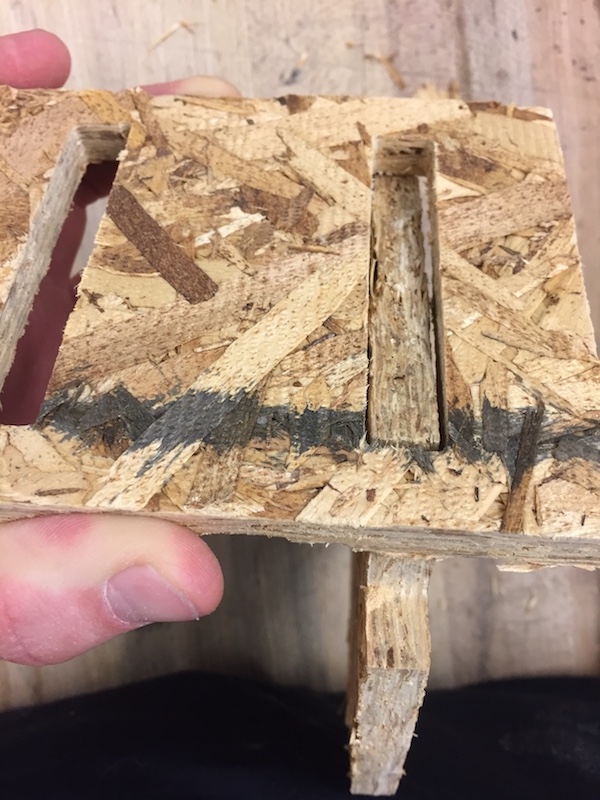
So because I used similar settings to the person before me (which the TA reccomended), I knew that the end mill was only going to cut to a maximum depth of 0.45 inches. This was supposed to be the depth of the wood, even though I had measured it to be just a hair less than 0.5 inches. Because everybody was more comfortable with using previous settings that TAs had reccomended rather than adjusting settings to what I believed would be right, this actually caused my wood not to cut completely through. I didn't realize this until everything was off the router because I expected my shapes to still be attached to the OSB by the tabs I had created.
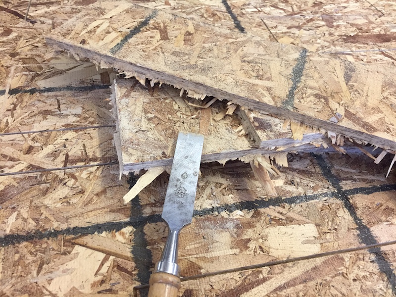
What this mistake meant was hours of chiseling though the wood to knock out the shapes, and then removing the splinters and sanding the edges. At least my mistakes are here to help the next group of students! And this is how institutional knowledge progresses...

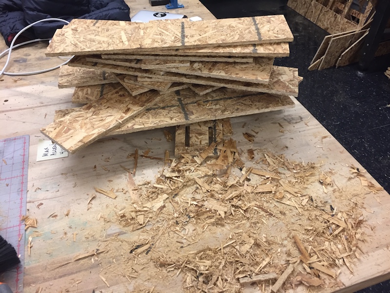
I also incurred some damage handling the rough wood, but nothing too bad.

Putting everything together
After that had all my pieces layed out, ready to go...
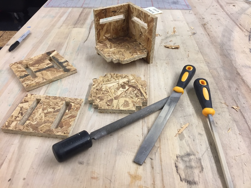
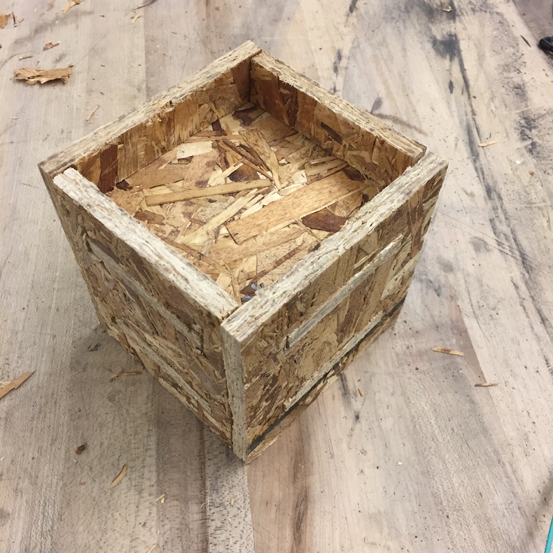
The press-fit "I" I had made for the MIT sign turned out alright. It didn't quite fit the first time, but after some filing of the edges, it fit pretty nicely into a cube shape:
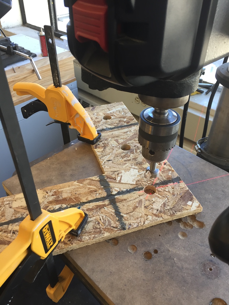
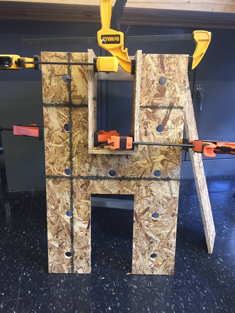
When getting ready to glue my HL sign together, I realized one thing: I didn't make any holes for the lightbulbs to fit through. It wasn't extermely clear what size hole I needed for the bulbs I bought because the thing the bulb screws into didn't have defined dimensions. So I kind of winged it found a tutorial using similar lightbulbs to estimate the hole sizes I needed. I ended up using a 7/8 inch drill bit, and used the drill press to cut out the holes I marked in sharpie.
The last step was to glue wood together and fasten the light bulbs

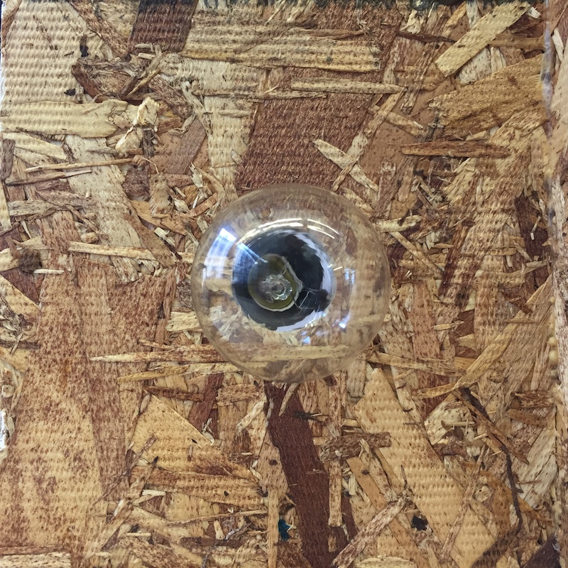

It ended up coming out really nicely and my friend was super appretiative!
Terminology
Drill bit, Routing bit, End Mill, Tabs, Toolpath Profile, Pocket Cut, Cut-depth, Flutes, Feedrates, Sacrifical Layer
Technologies Used
Shopbot, Drill Press, Files, Wood Glue and other woodworking tools, VCarve, Autodesk 360
Resources Used