Getting One's Bearings
This week was on Embedded Programming. This is the process by which we write code that will control our microcontrollers to do (almost) anything. Due to the depth and complexity of the architectures of the microcontrollers we have nowadays, this topic is certainly something that takes years of practice to really master.
In relation to modern microcontrollers and microprocessors that are in our phones and computers, the ATTiny microcontrollers are much more simple. That being said, there is still a host of things that the microcontrollers can do if one knows how to take full advantage of all their capabilities. Beginning to understand those capabilities and being able to leverage them in the programs we write was the task of this week. Besides reading this datasheet for the ATTiny44A, we were tasked to make the board we fabricated last week do something.
Please note that having taken MIT's Computation Structures course, 6.004 (for which there's an online version here), provides a lot of background knowledge that makes understanding the internals of a microcontroller easier. Without this knowledge, understanding the ATTiny datasheet, what registers are, and how program instructions are carried out in a CPU would be a massive bite to chew. Even with this previous knowledge, applying it in this setting and learning the additional knowledge about interfacing with MCU peripherals and all the individual characteristics about the ATTiny and how those are controlled using the C programming language is still a lot.
Reading the Datasheet
The full ATTiny44A datasheet is 286 pages long, and has basically everything an embedded programmer would need to know to take full control over every aspect of the microcontroller. This document is ground truth. It contains 27 sections, and covers topics from pin configurations to the CPU architecture to register descriptions to peripheral systems like ADCs, clock systems, and analog comparators. This document is a beast, and not something to memorize, but definitely a reference to keep close by.
The two things that immediately stood out to me were the feature list and block diagram of the ATTiny.

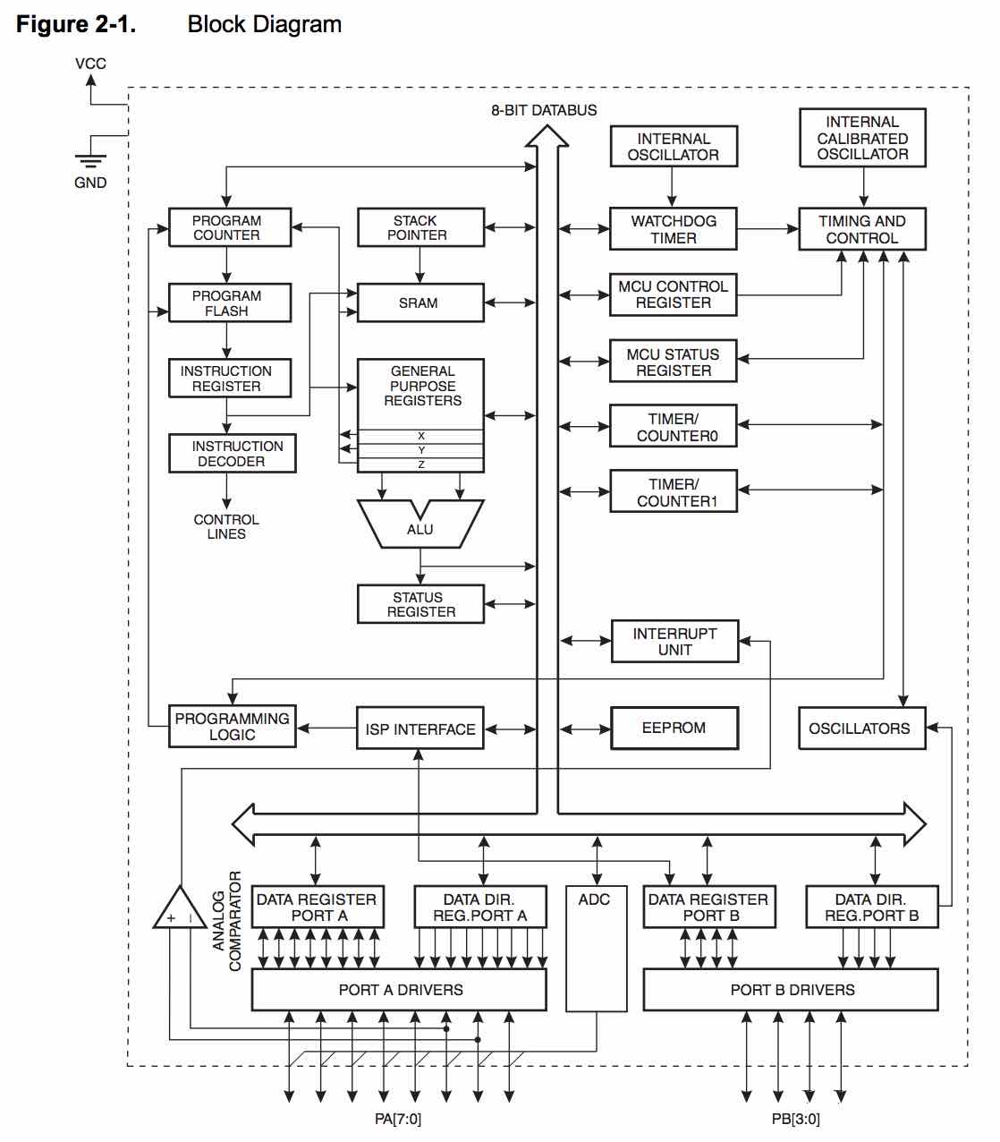
The features list stood out because it was a pretty succinct paragraph of everything you'd want to know in order to decide if this particular microcontroller fits your application needs. The block diagram for the ATTiny stood out to me because it looked really similar to what we talked about in 6.004. You can easily see the General Purpose Registers connected to the ALU block, the result of which is put into status registers. There's the Program Counter that feeds into the flash memory where the program is stored and retrieves the next instruction. What wasn't as familiar were all the peripherals on the right hand side and the I/O stuff on the bottom of the diagram.
The datasheet brakes down each and every one of those blocks down into their respective components, and gives detailed instructions on how to interact with them in assemby and in C.
Programming the Blink Board
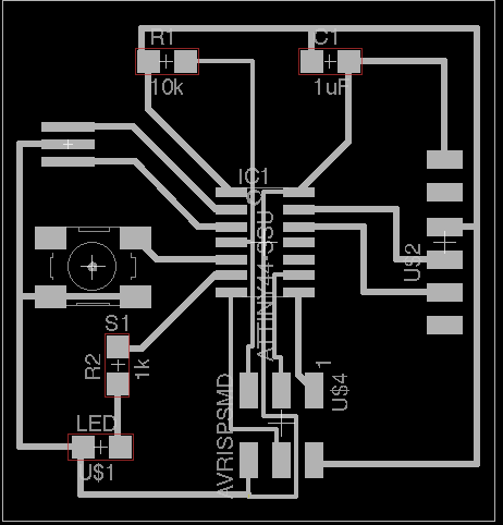
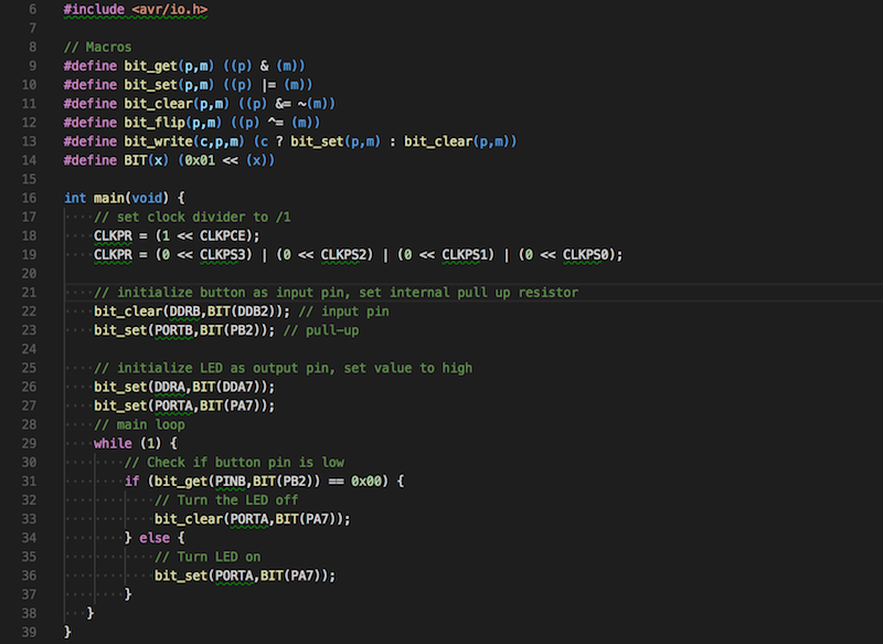
The programming assignment was to make the board I fabricated last week do something. The board I made was a fairly simple ATTiny44A driven board with an external resonator, an LED, and a button. So as my first real program, I wanted to make the LED turn on when the button was pressed.
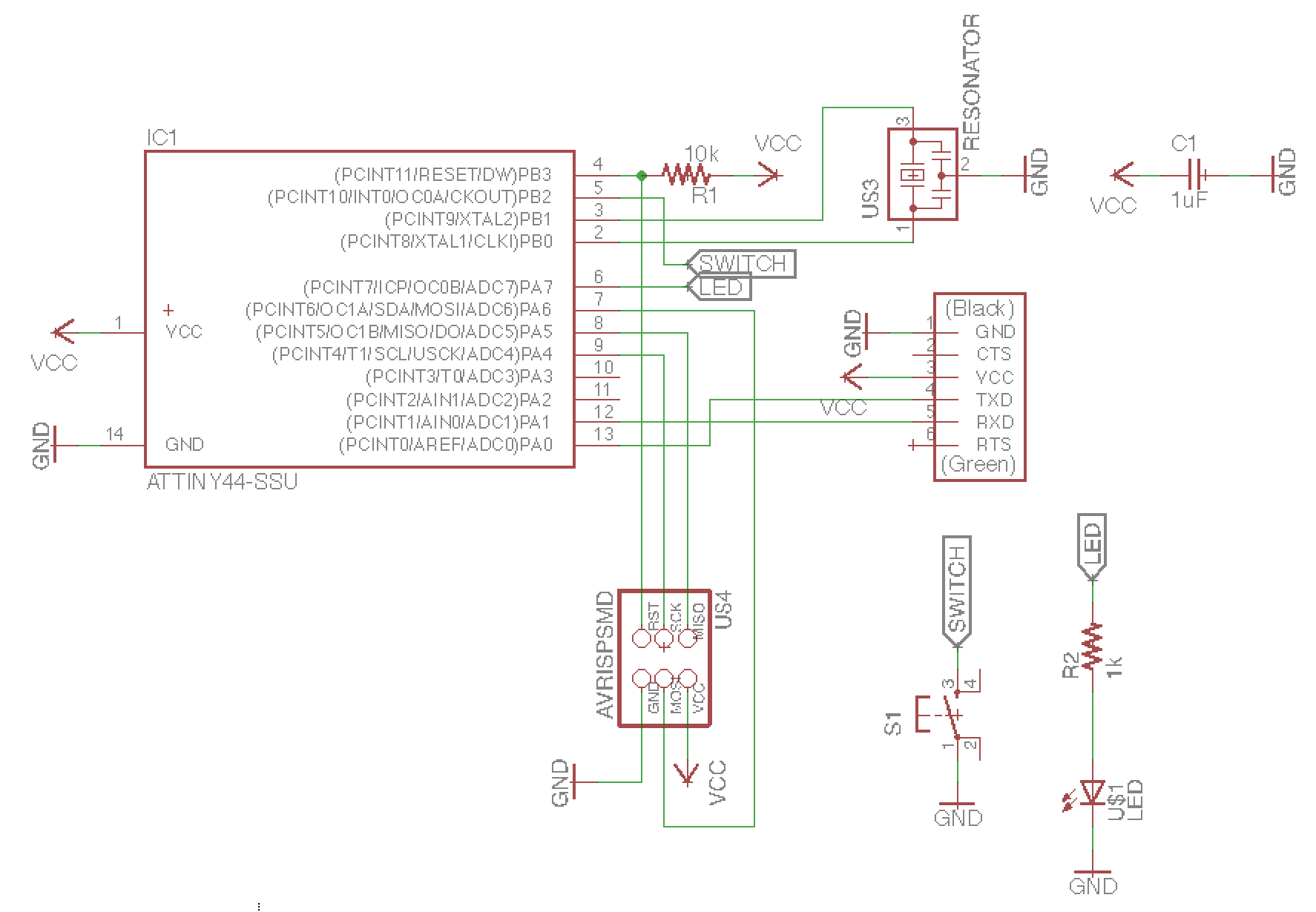
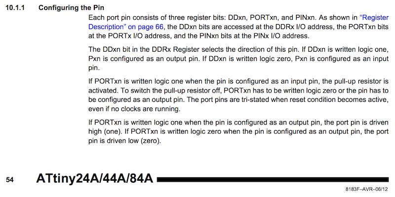
It's important to note that the LED I have is connected to pin PA7. Similarly, the button on the board is connected to pin PB2. In AVR programming, interfacing with pins involves setting or checking three main paramaters:
- The direction of the pin ~ either an input pin or an output pin.
- If output pin, whether the pin is driven to a high voltage or a low voltage
- If input pin, whether the pin is internally "pulled up" or "pulled down"
The logic of the program will be fairly simple: when the button is pushed, turn on the LED. Because of the specific circuit we have, checking whether the button is pushed and turning on the LED mean specific things with our input and output pins. The button is a switch connected to ground and connected to pin PB2 that will be set as an input pin with a pull-up resistor. Unpressed, the button pin will read high (it's being pulled up). However, when the button is pressed, the circuit will be connected to ground and the pin will subsequently read low.
The LED is more straightforward in that we are simply driving pin PA7 as an output pin. When we make it high, the LED is on. When we make it low, the LED is off.
Note that when I say "make the pin high," what that really means in the code as we'll see is setting a certain bit in a specific register to 1. When setting a pin low, that bit in the same register would be set to 0.
With the above description in mind, the code can be written (after debugging) as follows:
One problem I ran into was the LED not responding to the button. At first when I had the LED turn on when the button was pressed, I didn't know whether the problem was with the LED or button. So I changed the code to have the LED default on and turn off when the button was pressed. After programming this, the LED turned on by default but wouldn't turn off on button press. This way I knew something was wrong with the button and I decided to go in with the multimeter...
Probing the circuit with the multimeter, I discovered that the button was working properly. The pin was default high, and when the button was pressed, it got pulled to ground. This means something must be wrong with the code.
After debugging this for hours, both setting and reading pins both with and without macros, I finally figured out the problem. It wasn't an issue with how I was setting up the pin, or even with which pin I was trying to read in from. The issue ended up being a parentheses issue. In my "if" statement to check whether the button was being pressed, the incorrect code I wrote was:

And needed to be written like:

See that extra pair of parentheses? Yes, apparently it does make a difference. In fact, it makes or breaks the whole program.
To be honest, I'm not completely sure what was happening under the hood (i.e. what the assembly looks like to make that screw up), but I generally understand why the parenthesis need to be there. Inside an "if" condition, there generally needs to be a boolean (True or False), but true and false in C are treated just like numbers because that's how they're represented. So the first part of the expression "PINB & (0x01 << PB2)" basically creats this bit mask and does a logical AND with PINB so that it gets the value of Pin B2. Now what I wanted it to do with that value is compare it to 0 (or 0x00 in hex). But because of compilers and order of operations of instructions, this didn't work properly.
After I added the parentheses, which makes sure in the compiler that what's in the parentheses is evaluated first, the conditional worked and the light blinked! Finally!
Terminology
GPIO, ALU, Flash Memory, SRAM, EEPROM, Registers, Interrupts, Program Counter, Watchdog Timer, ADC, Analog Comparator, Fuses, Bitwise Operators, Logical OR, AND, NOR, XOR, Bit shifting, Bit mask, Makefile
Technologies Used
C Programming language, ATTiny44A
Resources Used