Molding and Casting
This week was a slight deviation from the past electroincs and CNC machining weeks. Molding and Casting is a fairly underappretiated method of fabrication in the mainstream media. Used together, they can allow for the fast and quick replication of an object. This is probably why you might have heard of "injection molding" as a manufacturing method for lots of plastic parts like fidget spinners and the like. However, there are many ways to use molds to make things. Methods such as injection moulding to vacuum forming to blow molding and rotational molding all use molds in different ways to create different classes of objects.
The most laborious part of the process is actually making the mold. After that process is done, you can use it to cast many objects with varying materials and properties.
An Ancient Board Game
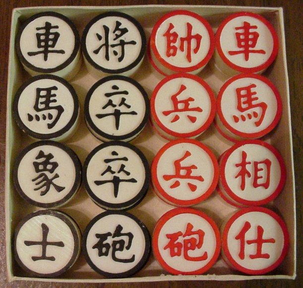
When deciding what to make a mold of for this week, I wanted to start off with an object that would only need a one piece mold. Multi-piece molds are possible and work well with planar symmatries in your object, but aren't necessary. Starting with a one-piece mold allowed me to get a hang of the wax-cutting and mixing processes that I'll get into later. One of the first things that popped into my mind was making pieces for a board game I had in my room: 象棋 (Xiangqi). Xiangqi is referred to as Chinese chess despite having a different board structure and piece mechanics. Check out a video of the board layout and piece mechanics here. The Xiangqi pieces look like this:
The Process
The overview of the process is as follows:
- Make a model of the actual object you're trying to create in a CAD program
- If necessary (>1 piece molds), break up your CAD model into the necessary shapes that will be your molds.
- Embed the model(s) into a rectangular prism that is the size of your wax block. This model includes your design and the block of wax and should represent what the wax block will look like after you mill it. Export this as an STL.
- Bring the STL from step 3 into a CAM program or into fabmodules.org. From here, depending on the program, you should insert your wax block demensions, your endmill size, and create BOTH rough and final cut toolpaths. Save these toolpaths.
- Using the toolpaths you created, use the mill you're familiar with to run the toolpaths with the proper feed rate to cut the wax mold.
- Now that you have a wax mold of the positive of your model, the next step is to create the negative mold of your object in OOMOO or some other mold material. Follow the steps in the data sheet to mix and pour this mixture into your original wax mold. Wait for it to cure.
- Finally, if you have a nice OOMOO mold of the negative of your object, then the final step is to cast your actual object using this negative mold. We used DryStone and Hydrostone mix for this final part. Similarly to step 6, follow the instructions to mix and pour your casting material into your negative mold and wait for it to cure.
- Take your final cast out of your mold, and complete any post-processing that might be necessary.
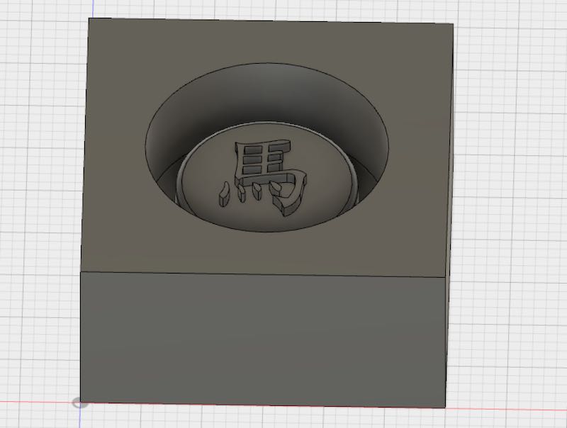
So I decided I wanted to start by making one of the Xiangqi pieces. My original plan was to make the horse piece, which has a 馬 character. My original plan was for the piece to be able to fit within a 1 inch by 1 inch square that (I expected) is typical for most Xiangqi boards.
When designing the model, the most difficult was getting the actual character as a vector outline so I could extrude it within Fusion 360. In Adobe Illustrator (AI), I used the text tool to insert a text box with 馬 in it. After choosing the font I wanted, I used the text -> convert to outlines function to convert the object from an editable text object to a compound path object. You should do this anytime you want to preserve font within a design and have to create a vector-only file for laser cutters, vinyl cutters, or exporting DXF or SVG. This seemed to work pretty well.
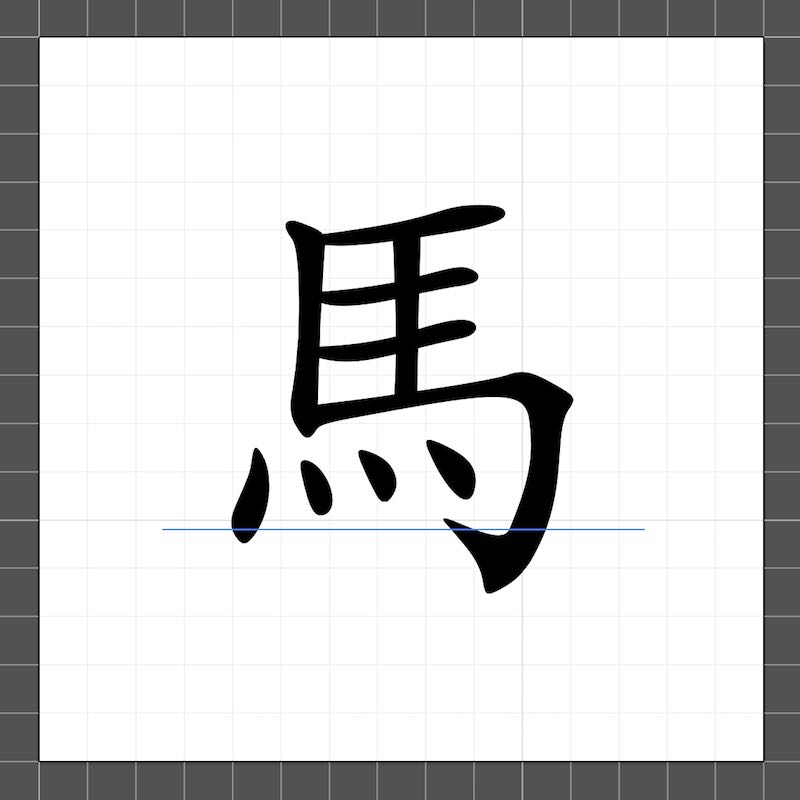
Beautiful, right? Maybe until you bring it into Fusion 360. One problem I had was properly re-scaling DXFs and SVGs in Fusion 360. Because I wanted a high quality image, I created an 1.5 inch by 1.5 inch file in AI with high PPI. However, importing this into Fusion 360 ended up being problematic because the DXF was so much larger than the size of my model.
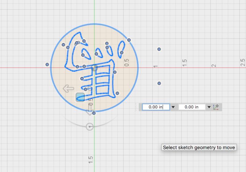
The actual issue with Fusion 360 was the way it handles these vectors. While AI treats the whole shape as one compound path, Fusion treats it as a collection of curves (bezier maybe?) and control points. The reason this is problematic is because you have to select everything before being able to scale or rotate it. Because of the complex curves generated by AI to perfectly fit the 馬, the control points were all over the place, and not highlighting everything would cause serious problems. For example, when trying to rotate my DXF 180 degrees, this happened:
Before:
After:
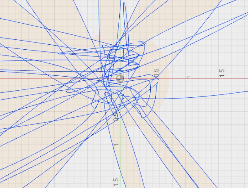
It was a mess, and extremely frustrating for hours while I tried different CAD programs and had issues properly scaling and rotating these DXFs that AI seemed to easily be able to manipulate. My end solution was this: I would trace over the 馬 in AI with the pen tool creating less acurate but much simpler paths. Then I would use those vectors and export as a DXF. This had little to no problems when scaling or rotating in Fusion, but you still needed to make sure you selected everything you wanted to scale / rotate.
There was, however, one problem. Detail. I was useing a 1/8 inch endill to cut the 3x3x1.5 inch block of wax. What that meant is that my extrusions couldn't be closer than 1/8", and ideally, were much farther apart than 1/8". Upon inspection of my model, I realized my vectors were going to be too close to cut:
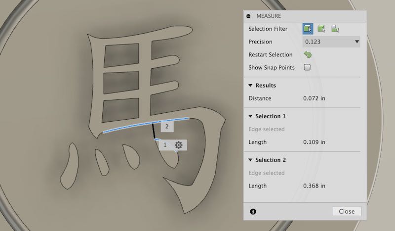
A distance of 0.072 inches wasn't going to cut it (quite literally). 1/8 inch is 0.125 inches. So I had two choices: make my model bigger until the distance was large enough, or choose a different, more simple, Xiangqi piece to model. I started with making the model bigger (re-scaling, yay!). Even making the piece the size of the wax block, the distance wasn't enough. So I chose to next model a 車. I thought the near horizontal and vertical lines that composed the character might work well with the mill.
After CADing the 車 in a similar way as the 馬 and making the piece double the original size (fit within 2x2 inches), I realized I still barely had enough room to fit the endmill in the middle holes:
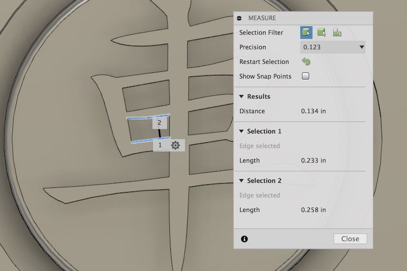
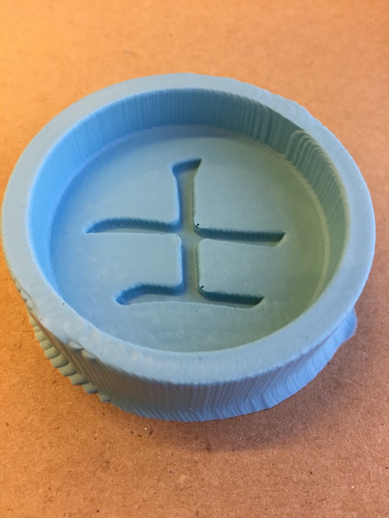
Even if it passed with 0.134 inches, this was still too close to 0.125 for me to feel confident about the quality of the mold. So I ended up re-CADing the simplmest possible character of all the Xiangqi pieces, the 士.
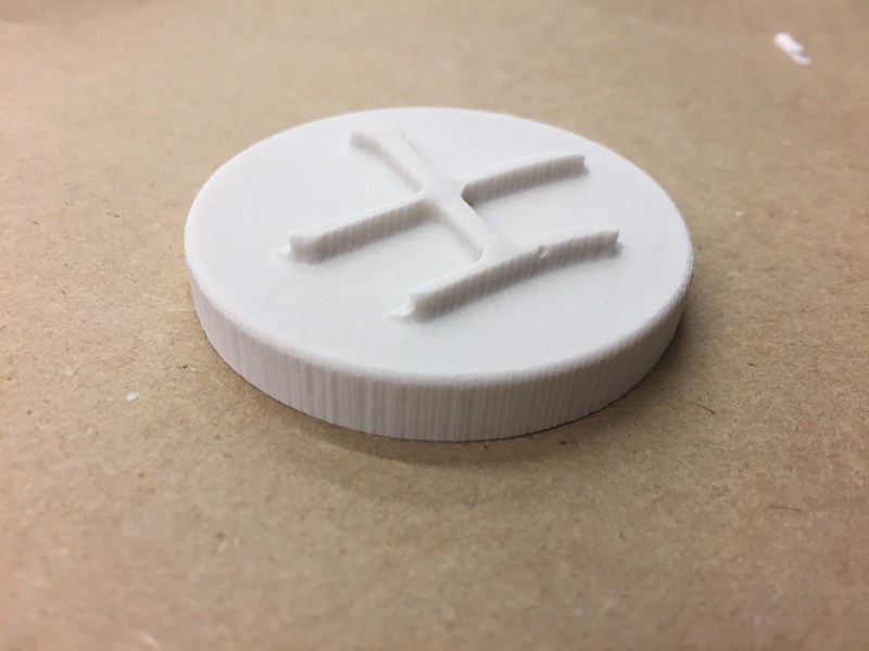
Lucky for me, this did the trick. So this would be my first model.
If you're thinking, "Why don't you just use a smaller endmill?" That's a very valid point, and I plan to do that to eventually create the rest of the Xiangqi pieces. However, this week since everyone was designing around an 1/8" endmill, the lab prefered not to switch out endmill until everyone first used the 1/8" one first.
Making the mold
After sorting out all the 3D model problems, I had my STL and was ready to move onto the next step of creating the toolpaths and actually milling the wax. While I wanted to use the Roland mill we used to mill the PCBs (because it had full 3D milling capabilities), the toolpath software was taking an extremely long time to generate toolpaths, and you had to use the computer attached to the mill because the toolpaths were dependant on where you placed your block within the Roland. All in all, there was a very long queue and people had spent 4-6 hours making little progress. So I instead used the mini Shopbot Shark in our lab. This router only has 2.5D milling capabilities, but I figured it'd be ok for my first mold. (To understand 2.5D vs 3D, see this article).
Using the small Shopbot was fairly easy. The CAM program took in an STL and given some more information about material dimensions, tool size, stepovers, and cut direction would produce a rough and final cut toolpaths that look like the following:
Rough Cut: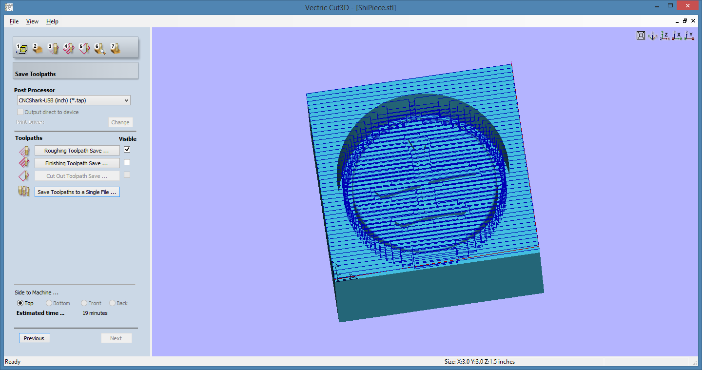 Final Cut:
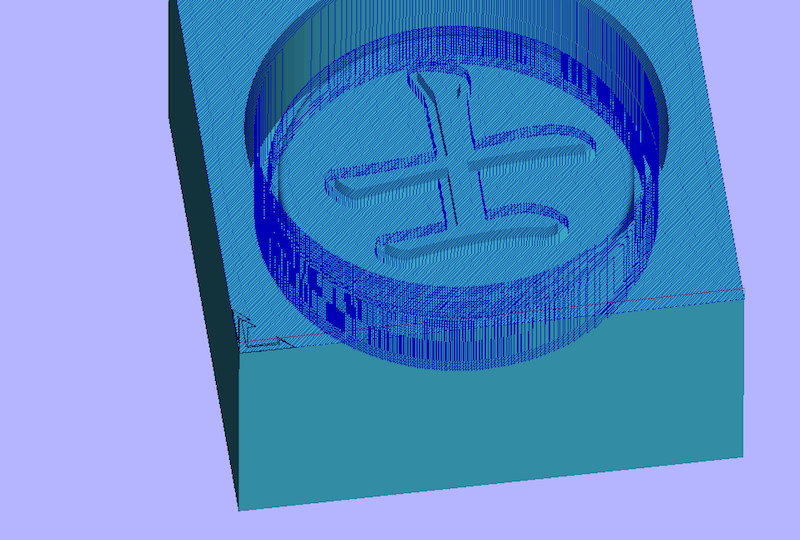
The rough cut toolpath is run first of the router and is used to clear out as much material as quickly as possible. Sometimes a larger endmill is used here, but you can kind of think of the rough cut as what Michelangelo had to do to get the general body shape of David before adding any of the details. Michelangelo probably used a larger chisel to remove a bunch of material before going in with finer tools. This is the rough cut. The final cut toolpath is where the endmill makes many passes over the finishing surface to get the surface as clean as possible. This is like Michelangelo making a whole bunch of finer chisels to reveal all the little details of David.
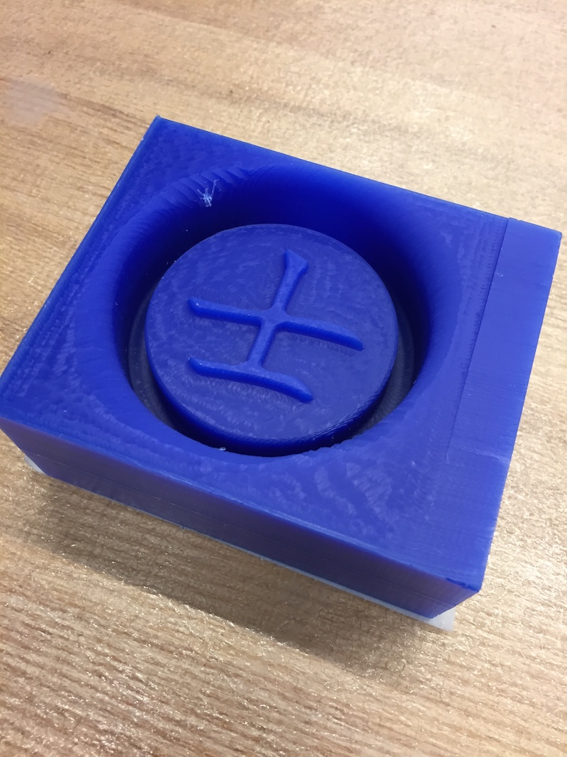
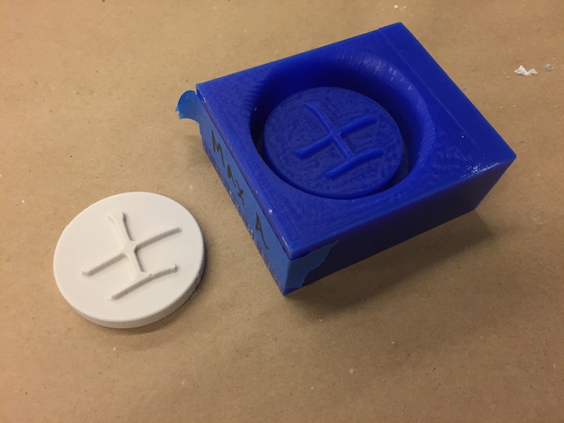
Half-way Done With Finishing Cut: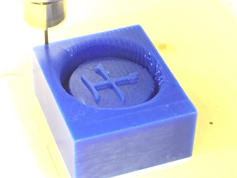 Finished Mold:
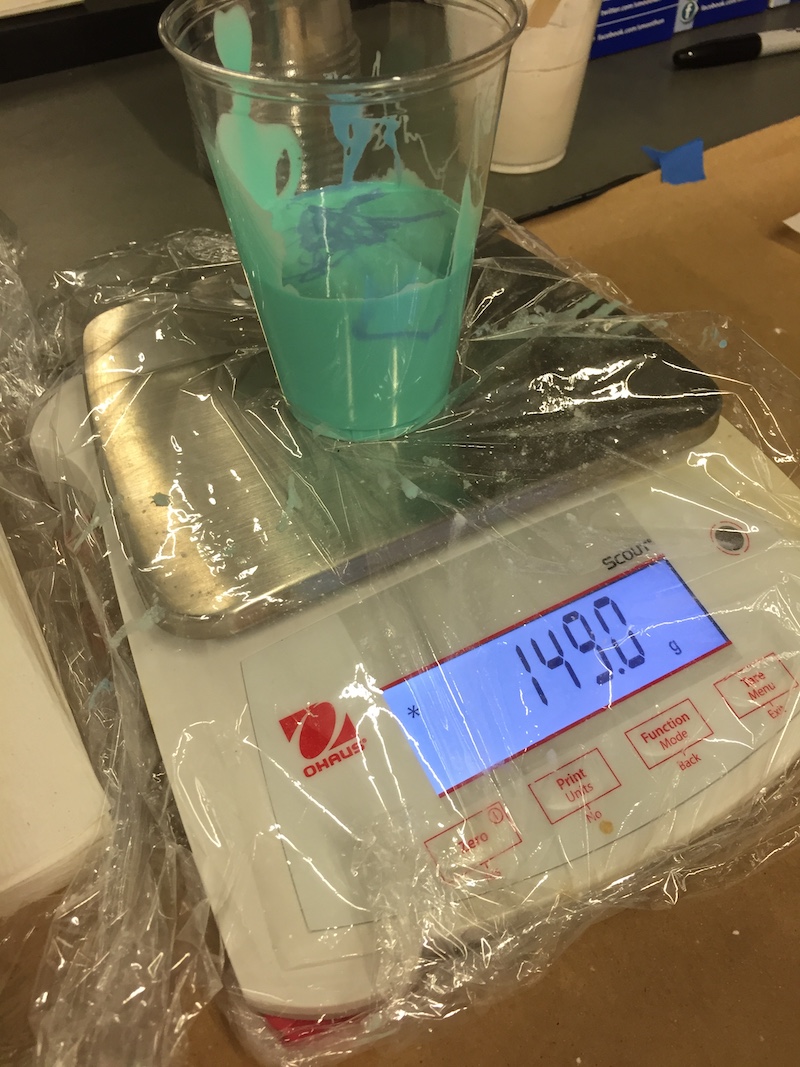
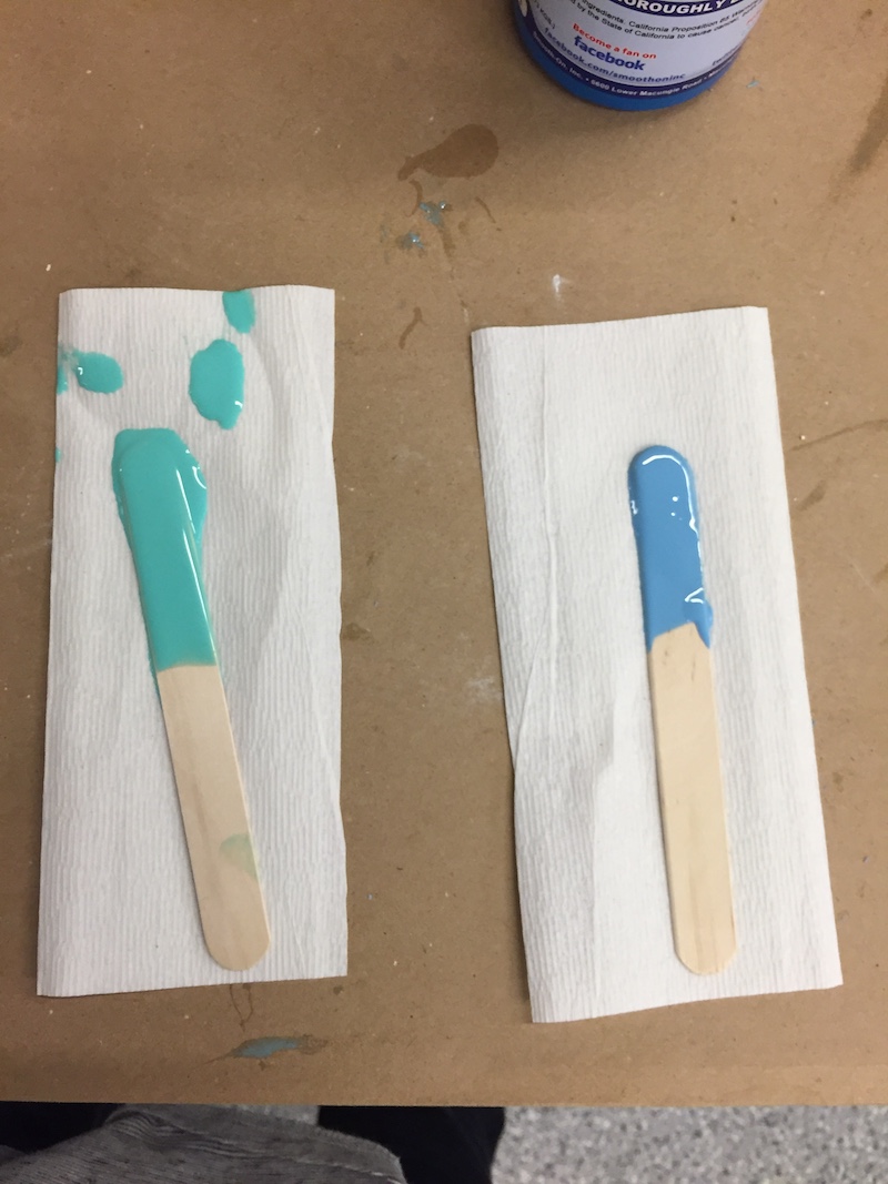
The next step in the process is making the negative mold of our object out of OOMOO. To make the OOMOO mixture, there were two solutions that you have to mix: Part A and Part B. You either mix an equal volume of both (if you measure by volume), or you mix 1 part Part A by weight to 1.3 parts Part B by weight.
You have to be really carful about cross-contamination of the OOMOO stock, so be sure to use separate paper towels and stir rods, and also make sure to put the caps back on the OOMOO asap as the curing process happens as soon as it's exposed to new air.
I kept track of the timing of everything from opening the bottles to when and how long I mixed the OOMOO to when I started pouring the mold.
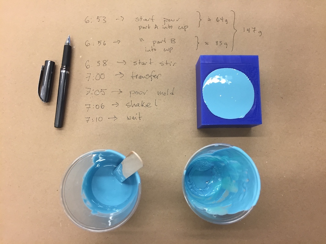
All together, the mixing and pouring process took a little less than 20 minutes, which is cutting it pretty close considering the pot time of OOMOO is 15 minutes.
Tips!
- Mix the OOMOO for one cup for about 2 minutes, then transfer the mixture to another cup and mix again for another 2 minutes. The transfer will help remove bubbles and you won't deal with mixture streaking that might have gathered on the sides of the cup.
- To help prevent bubbles, pour the mold slowly and let the mixture slowly fill in the cracks and crevices.
- To help remove bubbles that you may have introduced during the pouring, vibrate your mold side to side and even drop it from an inch or so above the ground to help bubbles rise to the top.
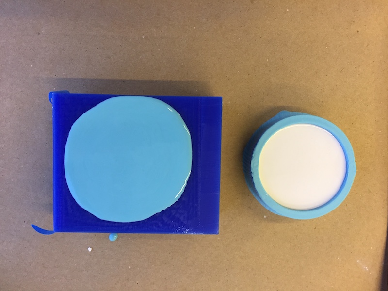
After letting the OOMOO cure over night, I pulled it out of the mold to find a relatively bubble-free mold:
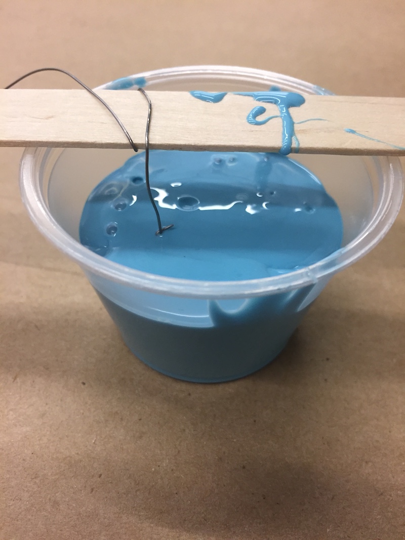
I also had some extra OOMOO when making my mold so I did what anyone would do which was find the closest object I could reach and put it in a cup and poured in the OOMOO. The object ended up being an Ohio quarter that was propped up by a wood paddle and some solder.
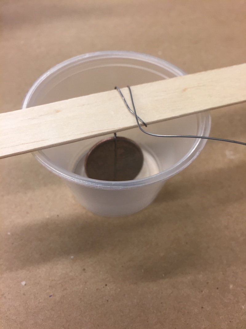
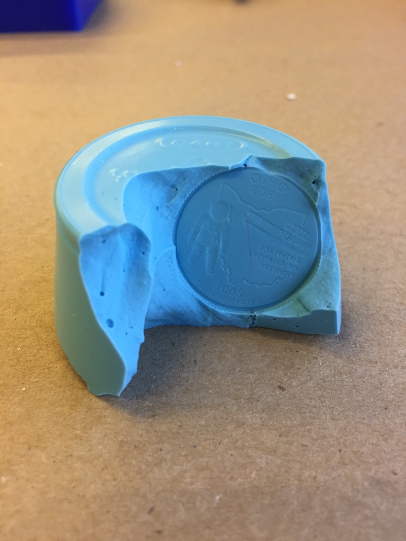
Cutting open that mold was difficult and perhaps unusable, but the quarter mold actually came out alright:
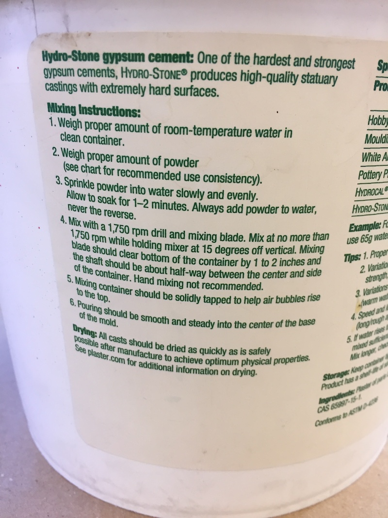
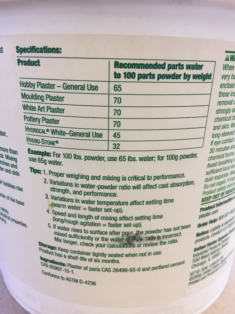
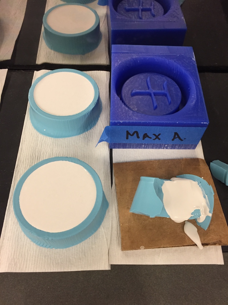
The last step was to mix Hydrostone and pour that into the negative OOMOO mold I had created. The instructions for the Hydrostone were a little confusing and didn't exactly say how long it would take to cure. I also misread water to powder instructions, but luckily was reminded by a fellow classmate before completely using the incorrect amount of water. The 32 next to Hydrostone (besides being completely different than the 65 parts in the example), meant that if you wanted to use X grams of water, you'd add an additional 3X grams of powder to that water to make the mixture, which alltogether would be 4X grams.
Our lab didn't end up using any drill to help mix the Hydrostone. Instead, we hand mixed it for a couple minutes unti homogeneous and liquid-looking.
Note that the instructions explicitly state, "Hand mixing not recommended." ¯\_(ツ)_/¯
Everything turned out fine, though. It poured well (although I didn't pour enough to fill the whole mold), and I also made another OOMOO mold using the same wax mold from before. Soon, I'll be able to create sets of Xiangqi pieces with high concurrency!
Terminology
Moulding, Casting, Machinable Wax, Mixing and Pouring, Curing, Shelf-life, Pot-life, Rough and Finishing Cuts, Cut Depth
Technologies Used
Machinable Wax, Shopbot, VCarve Pro, Fusion 360, Adobe Illustrator, OOMOO, Hydrostone, Drystone
Resources Used
- OOMOO and Hydrostone Specification Sheets!