It's Got a Pulse
My maze puzzle comes alive.
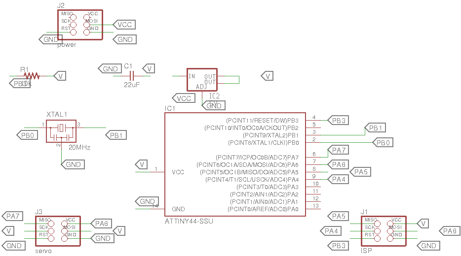
I decided to try to see if I could control a servo motor, since I was likely going to need it for my final project. I based my design on Neil's example servo PCB. A key adjustment that I had to make was that the voltage regulator was different, so I had to refer to the documentation to see what each tab connected to. Rob helped me to verify that the new traces were correct. When I designed my circuit board this week, I finally figured out some of the things in Eagle that were so incredibly frustrating the last time I designed a circuit board. Here's a list of some of the things I did this week that I wish I had last time:
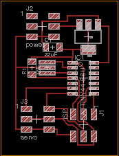
- Instead of literally connecting components with the net, just label what each component is connected to. This is much easier to read and understand. I still need to figure out how to flip the tabs though...
- Make sure to set the diameter and clearance of the tool in Edit > Net Classes so the traces don't get too close to each other. Manually checking this is difficult to do, but this was so much easier!
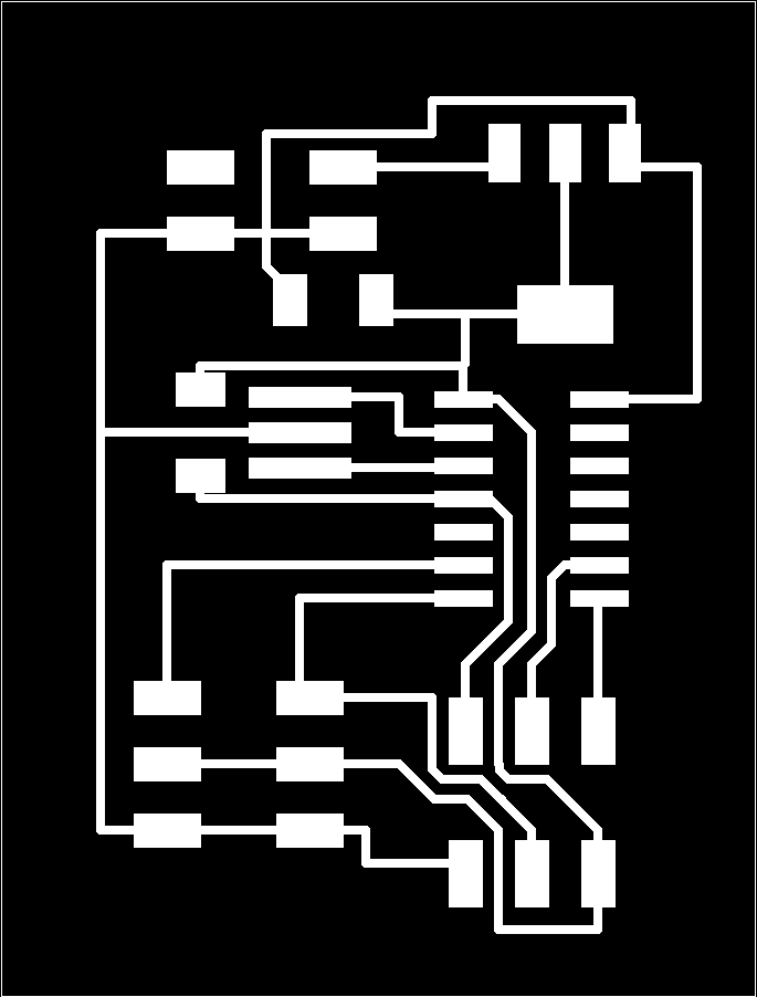
- If you don't turn off the layer that contains the border, you will get a frame around the PNG that is 1px wide. I didn't notice this until I was trying to cut it in fab modules. I was able to salvage this by inverting the image (my outline left enough room), but it would have been easier if I had just saved the image without the border.
- I changed the max milling depth for the traces to be 0.0045 in, and I didn't have to mill it twice. I also reduced the mill depth on the outline to 0.067 and it was still more than enough.
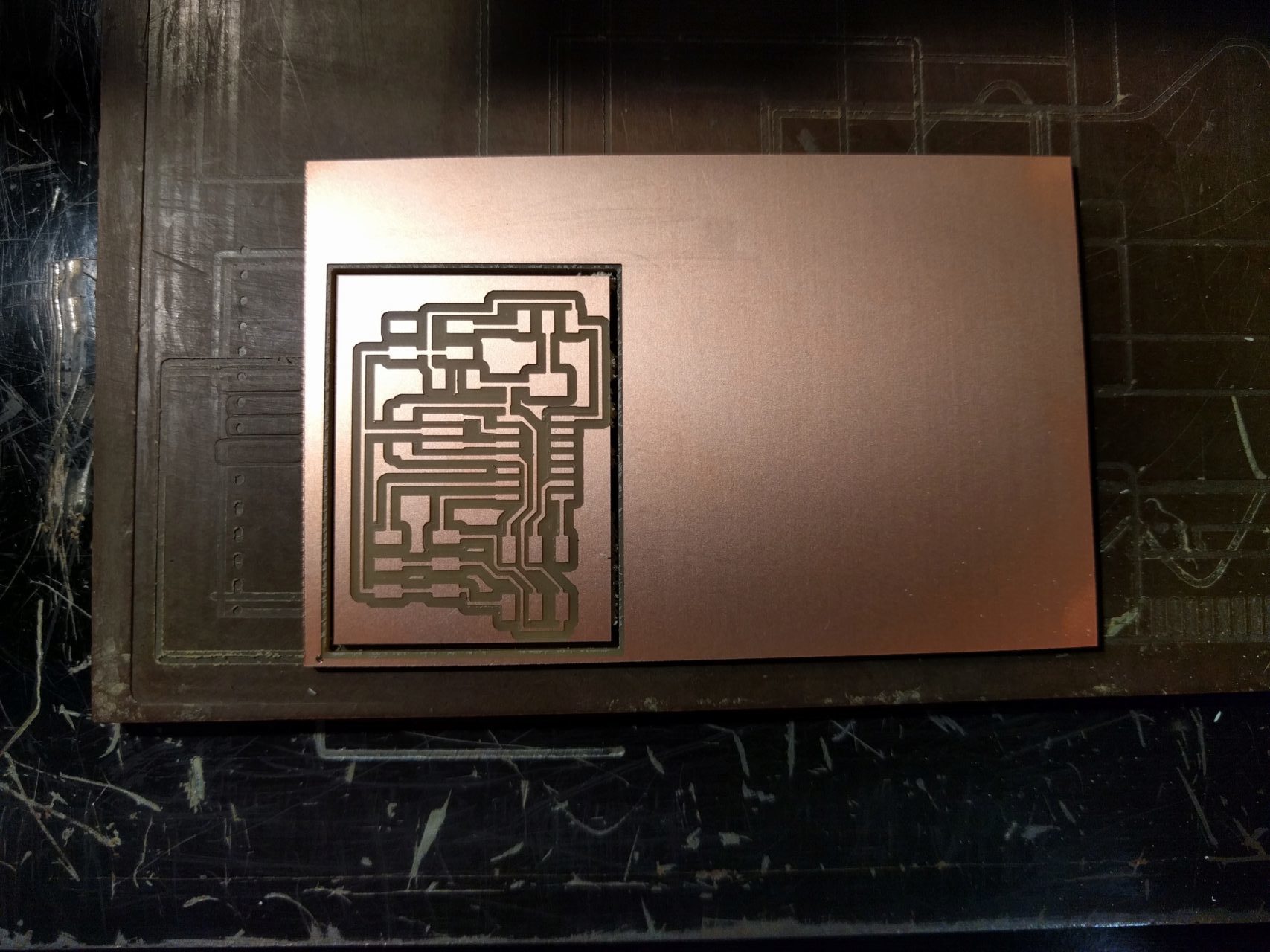
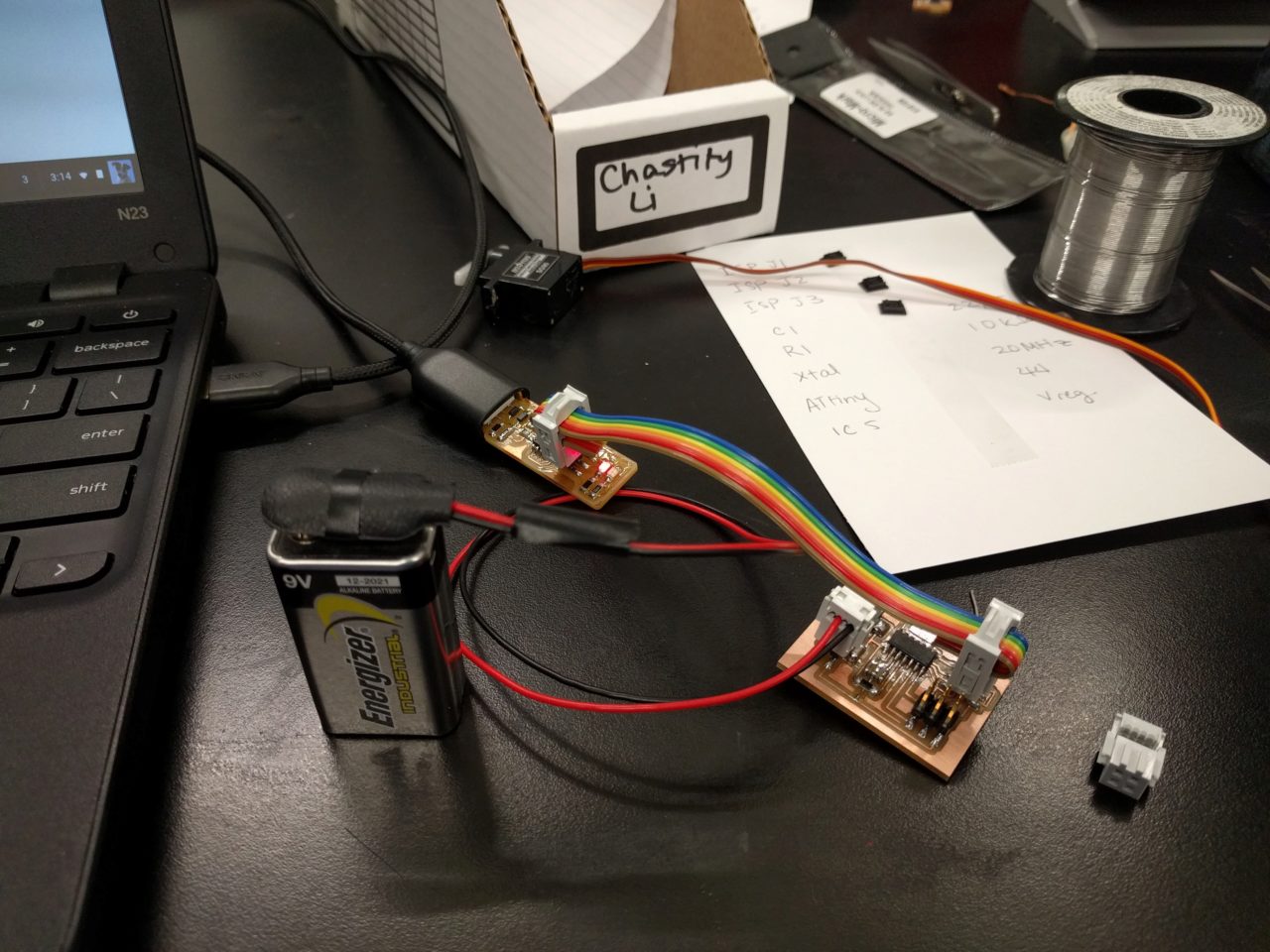
After milling my PCB, which was largely uneventful except for the minor adjustment to the trace, I soldered the parts. The resonator still gave be some trouble, but other than that, everything else went smoothly. I checked for solder bridges and good connections with a multimeter before attempting to program. Rob suggested that for quick and easy debugging, we could just use a simple 9 volt battery and a connector cable. For the final project, I think I'd try to use a more sustainable source. Because I had heard horror stories of some people's circuit boards smoking after they had connected it to power, I triple checked all my connections from the board to the connector cable and made sure they were correct before connecting to power. After a tense few seconds of waiting for smoke or fire, I felt confident enough to connect it to my fabISP.
I initially just took Neil's code and directly uploaded it onto my PCB, just to make sure it was functional. I first checked to see if my programmer could recognize the servo PCB with avrdude -p t44 -P usb -c usbtiny (I learned that the 't44' is in reference to the microcontroller on the board you are trying to program, and not the microcontroller on the programmer). It initialized properly. I next used the command make -f hello.servo.44.2.make to create the .out and .hex files. I then used make -f hello.servo.44.2.make program-usbtiny actually program it. It programmed nicely, but when I attempted to append -make fuses as I did last time, it spit out an error. The ISP had successfully programmed the servo PCB, but had not set the fuses. When I connected the servo motor, it spun to one side and got stuck. Rob suggested that I look at the makefile, and indeed, I should have appended -fuses. Rob explained to me that by failing to set the fuses, the servo PCB was using the internal clock that it had, and not the external 20MHz resonator that the code was referencing. The de-sync was confusing the servo motor so it got stuck. After I set the fuses, everthing worked as intended.
I next read the data sheet for the servo and modified Neil's code to make the servo do something that was closer to what I wanted for my final project. I made the servo motor turn to a specific position and them wait 2 seconds before returning to the origin, waiting 2 more seconds and then returning to the that position. I kept it on repeat, but when I have more pieces of my final project, the different servos will wait indefintely until the maze is solved. The idea is that multiple servos will control the different rings of the maze, changing the puzzle each time you attempt it. I still need to fgure out how to get different servos to control components that are co-axial without making the project too big.
Update! I actually ended up using the board I modified this week in my final project! Had to make slight changes to the code, but it works well!
Special thanks to Rob and April for their help this week!