"It should only take an hour"
Hahaha...
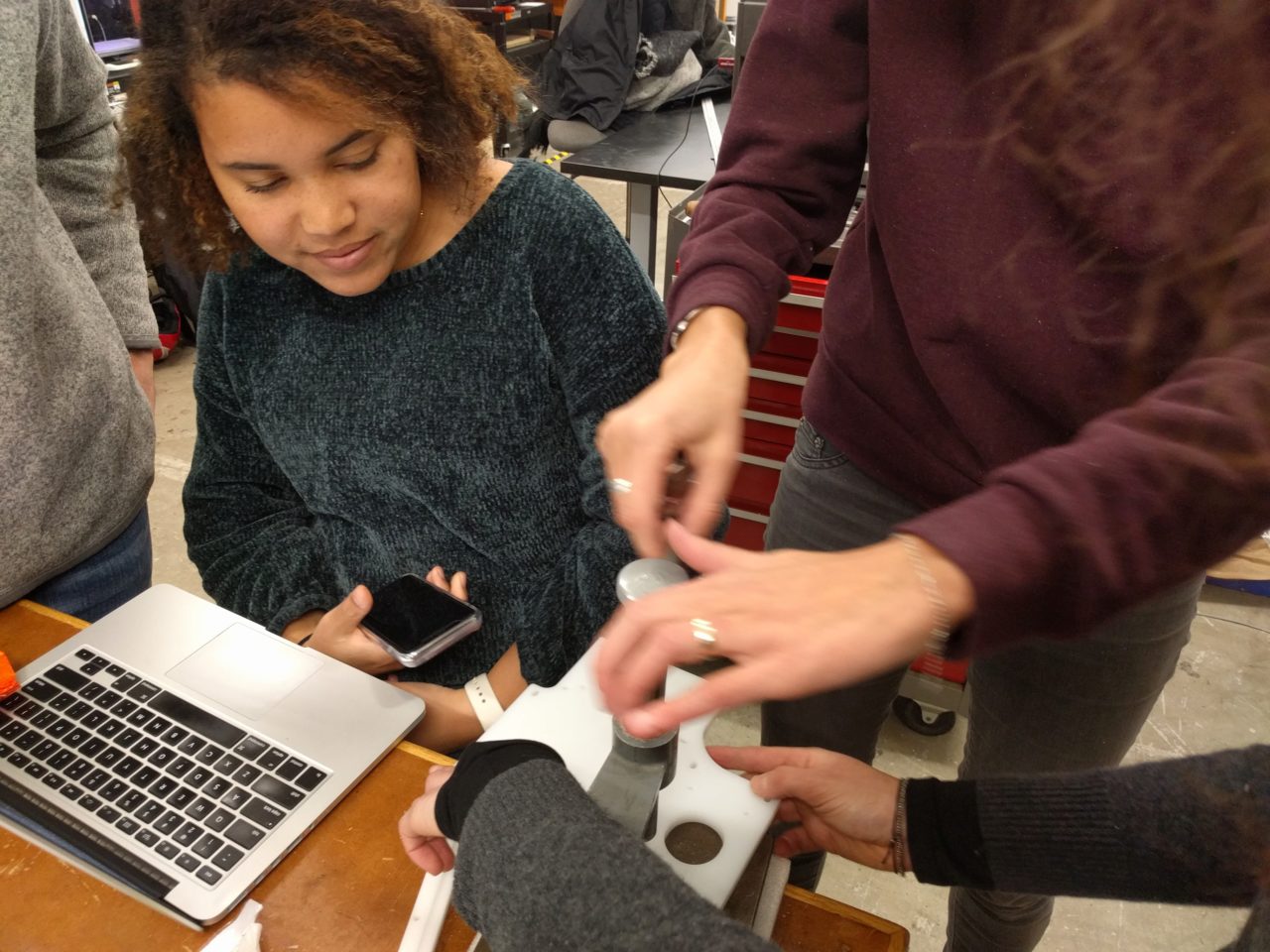
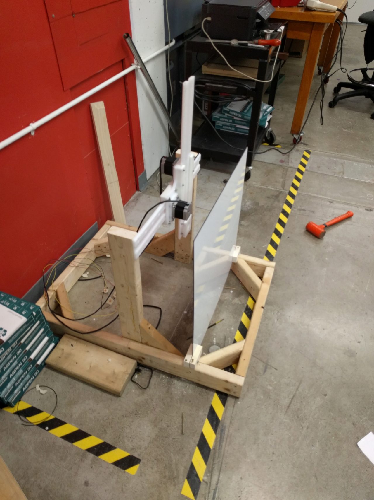
For this week's make a machine assignment, I was in the assembly group. Our job was to assemble all of the disjoint components and troubleshoot any problems we ran into. The first problem we ran into was joining the two axes that were independent degrees of freedom. After tossing around the idea of using epoxy, screwing them together, or somehow using them independently, we decided in the end just to mill the piece from Jake's original design that combines both degrees of freedom. Danielle moved the design from Rhino into Vcarve and other members of the machining team helped cut out the new piece. Afterwards, we all helped with taping and the general assembly of the new part.
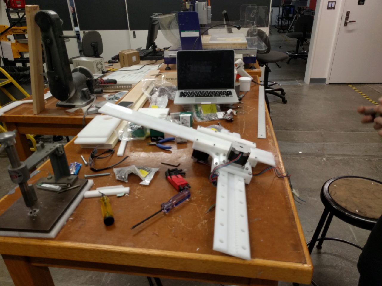
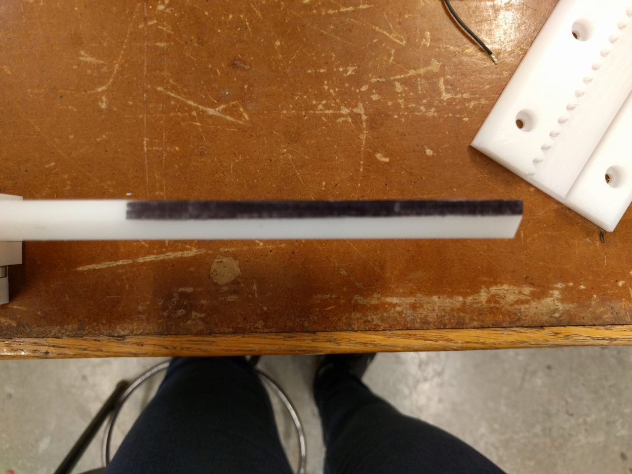
We ran into some issues where the rack was uneven, so one side was really tight in the channel, and the other side was a bit wobbly. I spent some time trying to figure out the best way to split the difference. The end result isn't perfect, but it isn't too bad. Rob helped to identify the cause of this issue as the sacrificial layer being uneven.
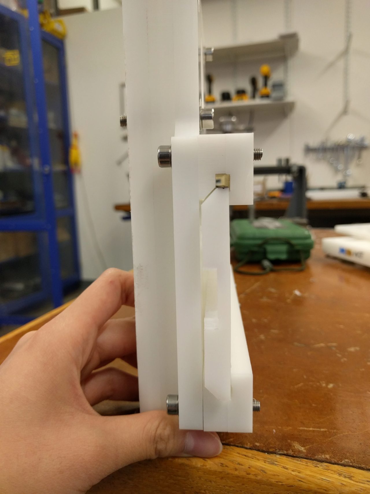
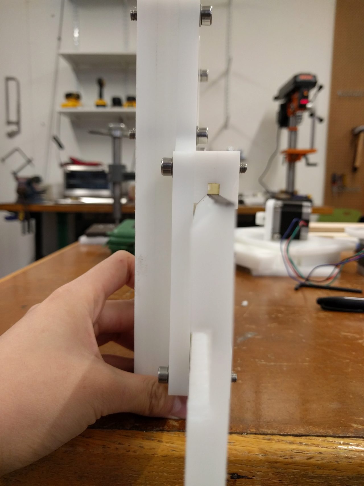
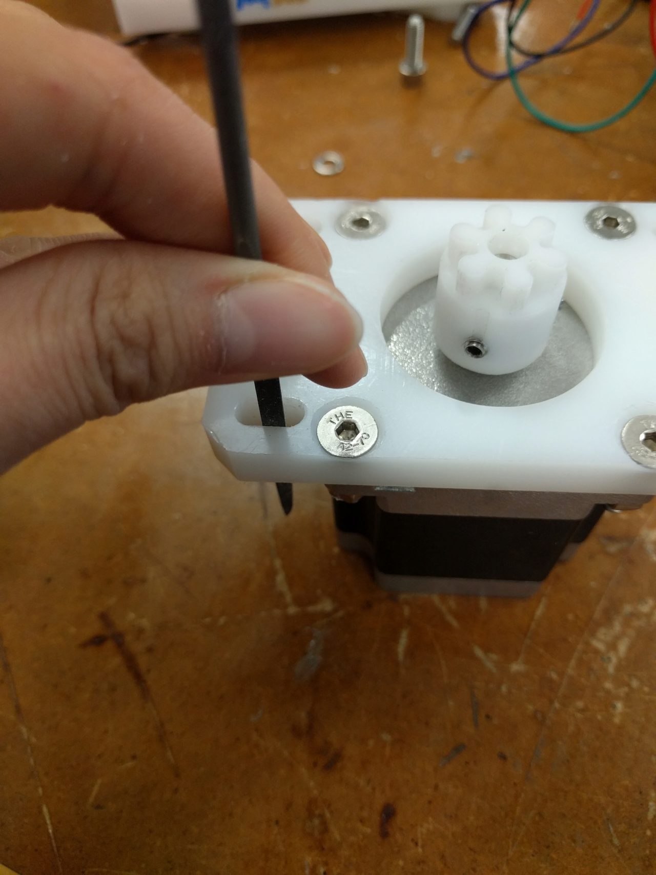
Although the process seemed straightforward, there were a couple of subtle things that we had to do in order to be able to effectively adjust the tolerances. The first thing was making sure that the screws actually slid in the slots. After assemblying the part a couple of times, the threads on the screw tore chanels into the slots that prevented the motor from moving freely. When sliding the motor back and forth, if it got caught, it was difficult to tell if the teeth were actually engaging, or if the motor was just stuck on the screw. I went back in with a file to smooth the edges so that the screw could move freely. I didn't remove too much material, so it didn't affect the screw and washer's ability to hold to parts firmly together. But it moved much more smoothly, and I was able to get the pinion mounted on the motor to mesh much easier.
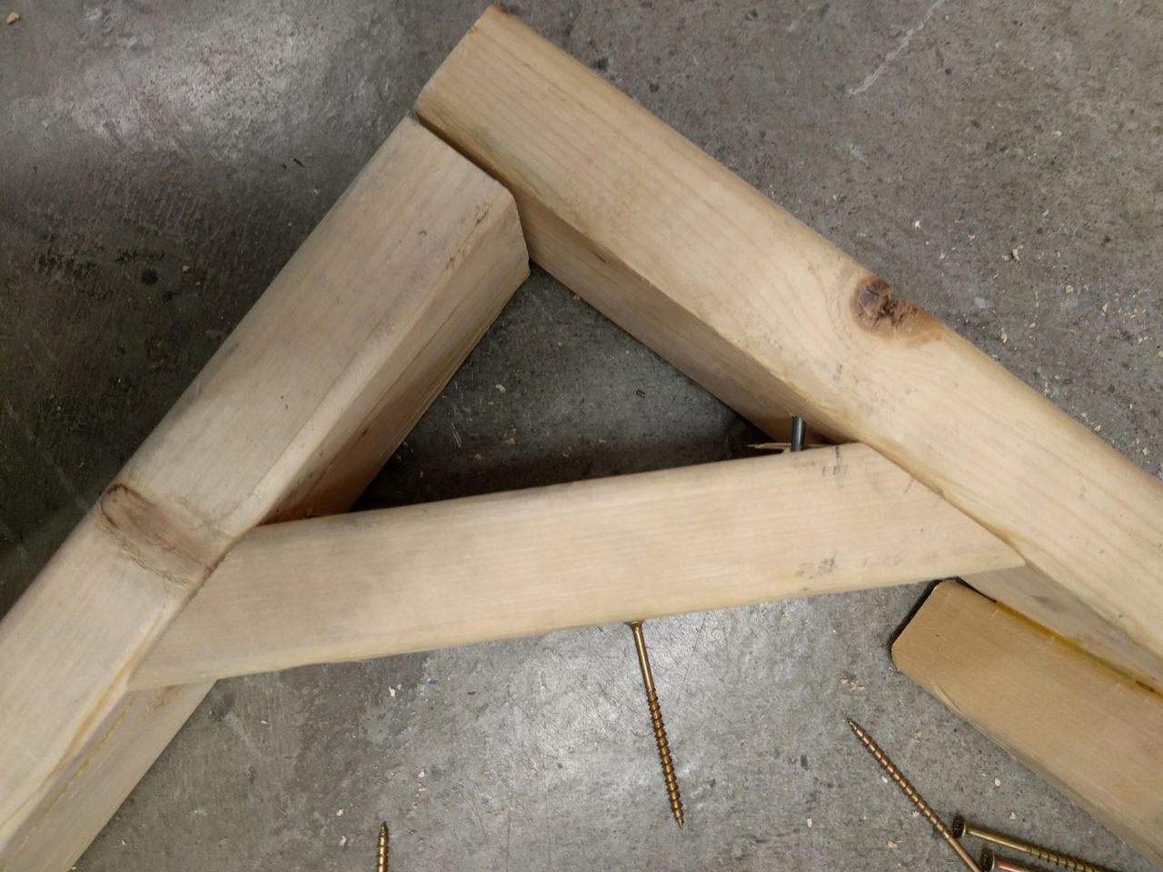
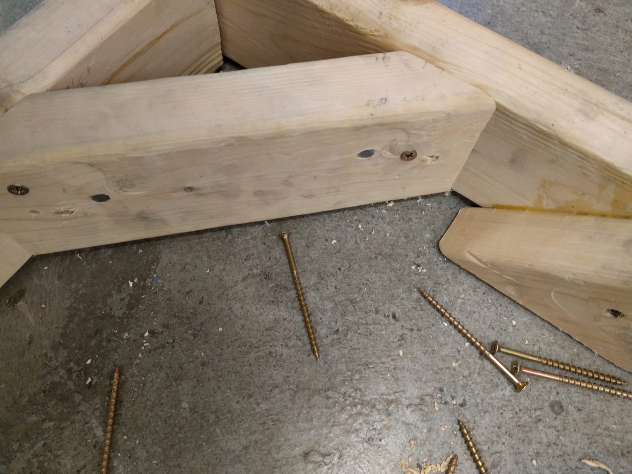
Next, I asked Rob for some longer wood screws to see if we could make the wooden frame a bit sturdier. The previous design used primarily long nails to hold the frame together, but as we moved the frame around the joints wiggled loose. It was actually quite difficult to work around the existing nails, because I didn't want the screw to hit a nail or for the sharp end of the screw to break out of the wood. In the future, I think I might have removed the nails so that there wasn't any danger of the screw running into the nail. April and worked together and in the end, we managed it without running into any nails.
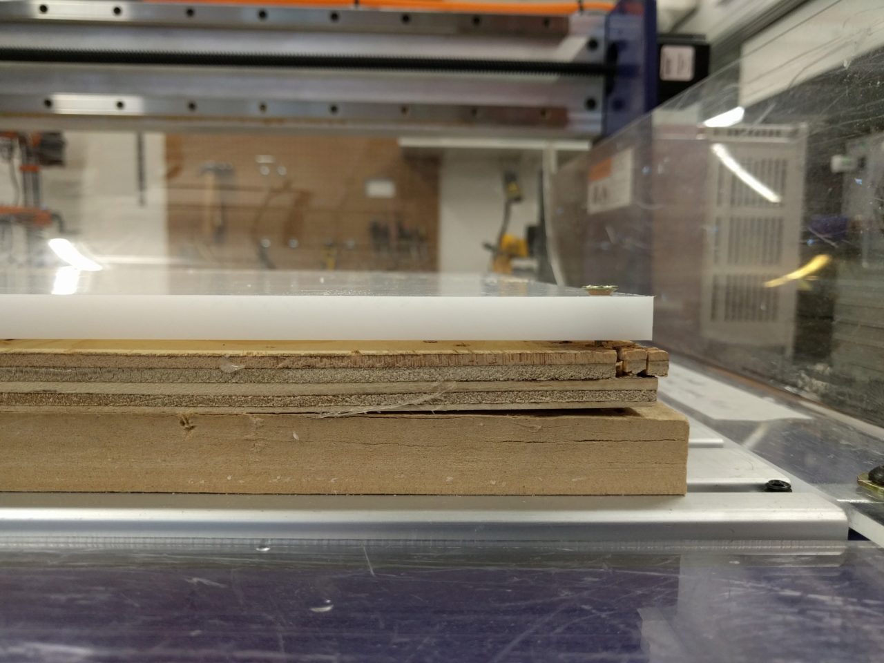
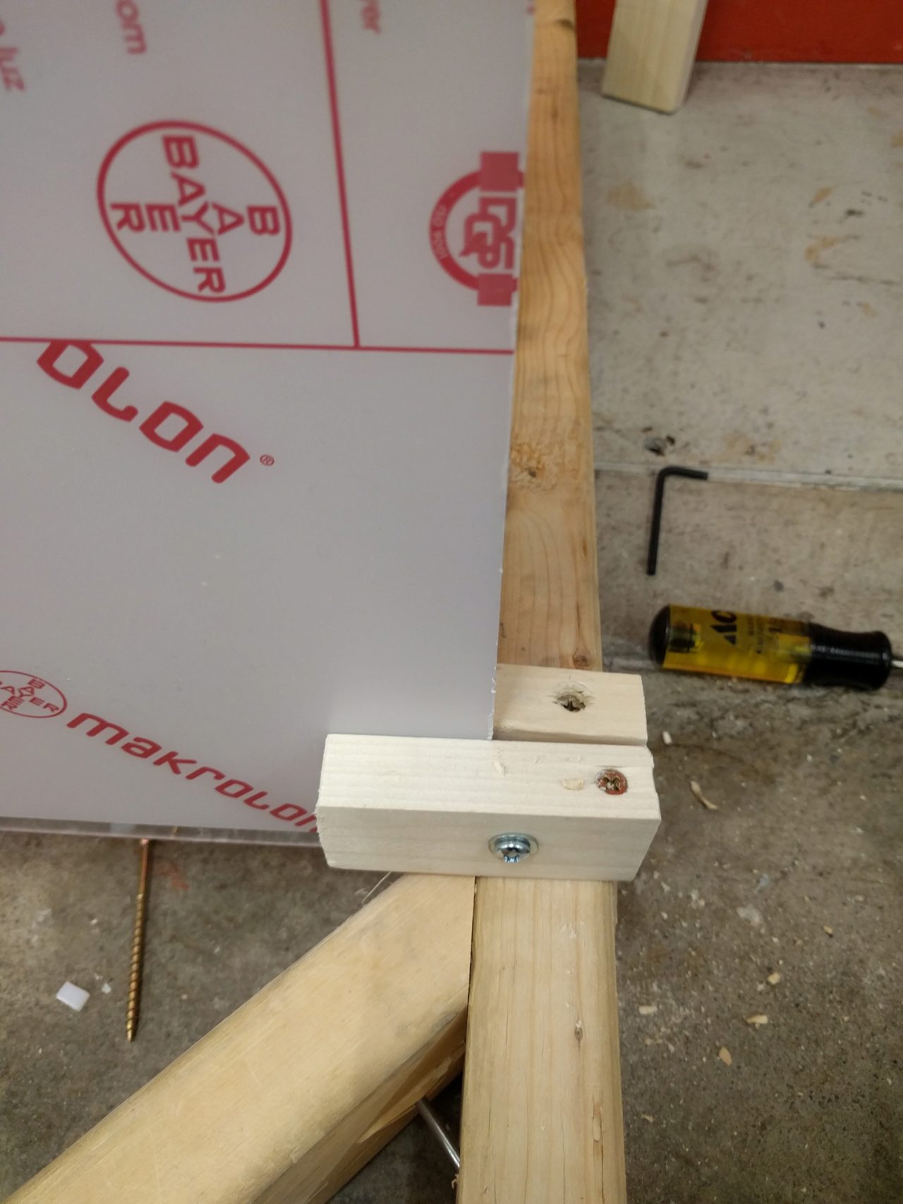
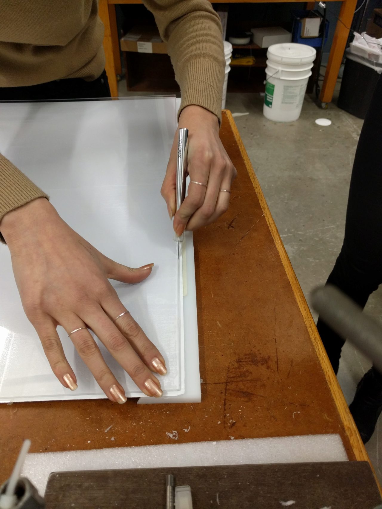
We then needed a way to hold a piece of acrylic up to the moving flashlight, so Diana and I worked on cutting channels in the frame, we tried drilling a hole close to the edge and chiseling out the bridging part. This was both slow going and scary. Also, the end result wasn't sturdy enough, so Richard and I added scrape blocks of wood to sandwhich the acrylic on either side. The end result was much better. It wouldn't be strong enough to do any other type of machining, but for our purpose of light drawing, it was enough. We then afixed the photo paper onto the acrylic. It was oddly satisfying, a bit like putting a screen protector on your phone, but much larger scale.
For final results and for more detailed documentation, visit the Harvard Machine Documentation Page
Special thanks to Rob, Richard, Diana, April, and Julia for their help this week!