e m b e d d e d P r o g r a m m i n g
let There be light. this Week's task was to program the LED on our week4 board to turn on and off with the button. i Will first list the steps that eventually got the board working. then I'll follow with the long list of troubleshooting and things i learned along the way.
programming in C
scrolling Through many previous student's pages, i realized all i needed to do was change the source code examples to match the board's LED and button locations. to Get the correct locations and names i referenced the data sheet. the Most helpful tutorial was Rob's walk through of three examples. i Ended up playing with the last file because it explicitely #defined everything, making it easy to follow and change the code to match my board. after Using Xcode to change the source code in the .c file and reading through the .make file, i ran the following in my terminal:
- make -f button.make
- make -f button.make program-usbtiny
- make -f button.make program-usbtiny-fuses
i Programmed my other board from week4 as well to verify the process. the Programmer and the board are still connected in these photos. also The blue LED was dimmer than the red. i Am assuming this is because of the tiny traces acting as a high resistor. the Resistor here is probably not even necessary.
some troubleshooting notes: make sure the board and the programmer are recognized. OXS's terminal does not have a lsusb function by default. instead go into About This Mac >> System Report >> Hardware >> USB to expand the tree and check for the board and programmer. my Programmer did not work plugged directly into a USB port. but It did work with an extension cable.
programming with Arduino's IDE
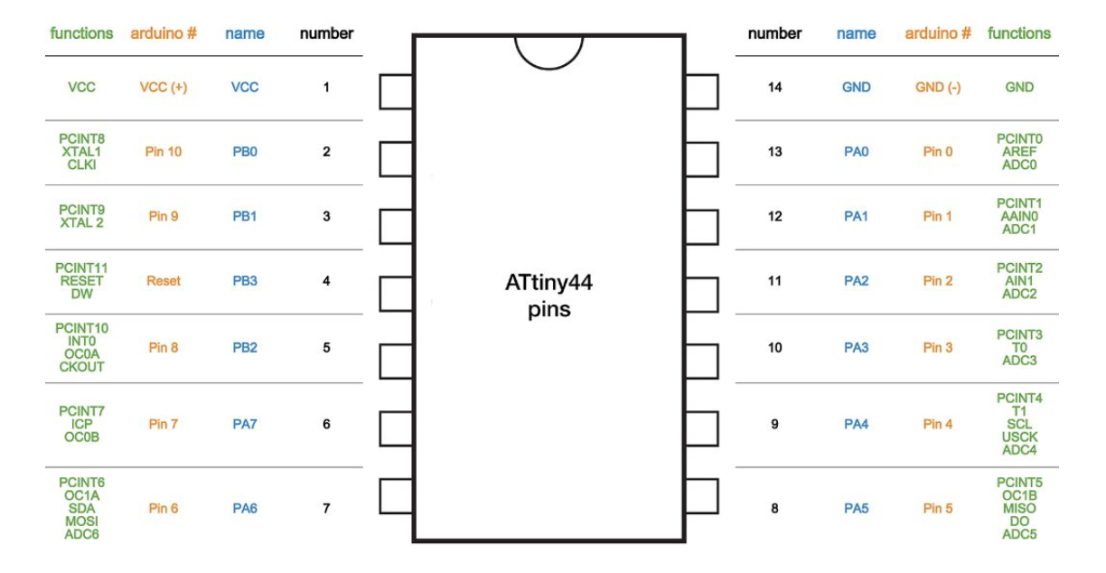
i Moved on to programming in Arduino's IDE. it Was much easier to get started, after downloading the ATTiny library and adjusting the board, programmer, and clock settings i opened up a sample sketch and changed the LED pin number, uploaded it to the board and it worked immediately. the Pins are numbered differently and i found this chart from a prior student, Jiamin, to be extremely helpful.
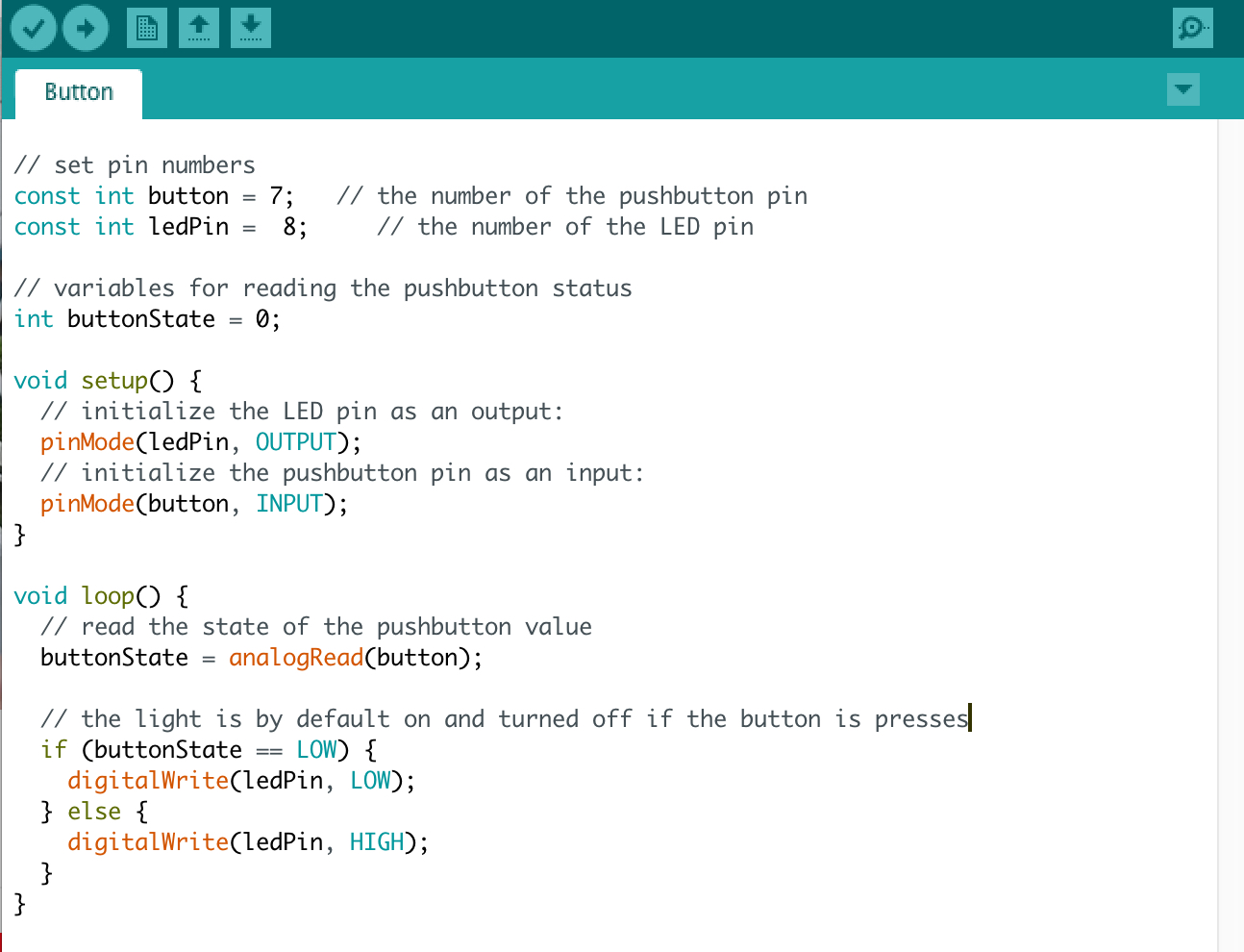
next, I opened the sample button code and changed the pins. this However did not work, until i changed 'digitalRead' to 'analogRead'. past Class examples worked with 'digitalRead', however they button was set to a different pin. are Some pins only able to output digital and some analog? i Read through the attiny data sheet but was not able to confidently answer this question. more To investigate.
in The meantime, i also investigated why we had to 'burn bootloader'. my Functional understanding is this (adopted from aruino website)...the bootloader is the firmware in a microcontroller that installs new firmware without the need of an external programmer. with Our setup we have an external programmer, the USBtinyISP. to use the full flash of a chip or avoid bootloader delay, we "burn the sketches" using an external programmer. functionally it seems analogous (but not the same) to the "make -f button.make program-usbtiny" and "make -f button.make program-usbtiny-fuses" commands we typed in terminal when programming in C.