Week 5: Electronics Design
In week 3 we focused on electronics fabrication: given a schematic and traces for the schematic, can you cut the traces, stuff and solder a PCB? The pre-fab (EDA or ECAB) and post-fab (AVR programming) stages were abstracted away. In week 5 we stepped back a bit and focused on the pre-fab (and in week 7 we’ll focus on the post-fab).
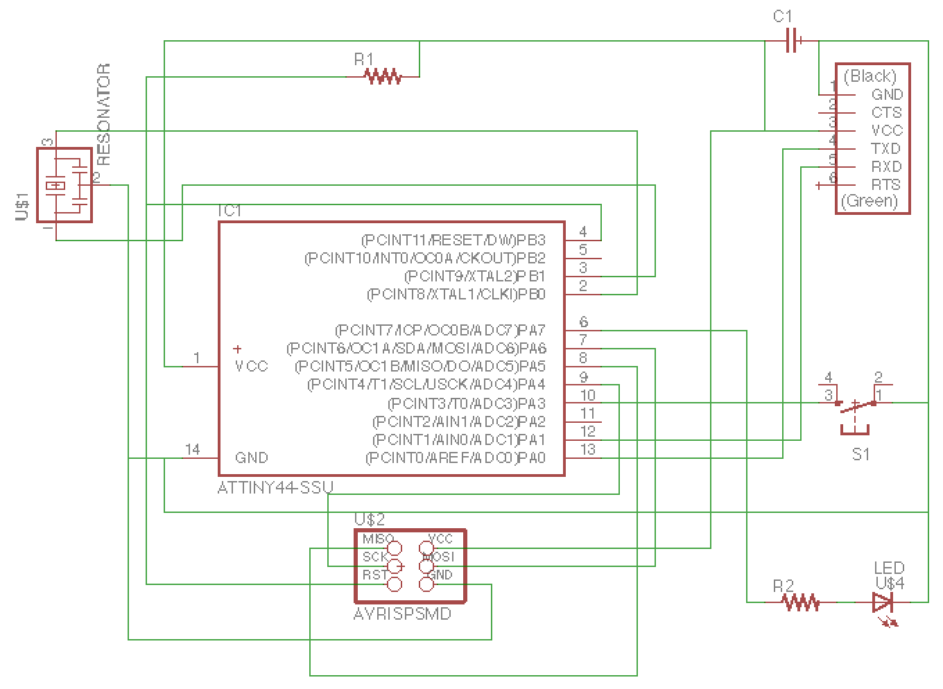
Though we started to step below the abstraction barrier of “the schematic simply exists”, the training wheels were not off (for me). We were basically replicating a Hello, World board from Professor Gershenfeld and adding some simple components. Again, Professor Gershenfeld took us through a suite of tooling for EDA although I stuck with Autodesk’s EAGLE (Easily Applicable Graphical Layout Editor) software for schematic design and board design. I didn’t try out any of the simulation tools, so I’ll have to return to this sometime soon.
I started with a slew of tutorials (here, also here, and also here)
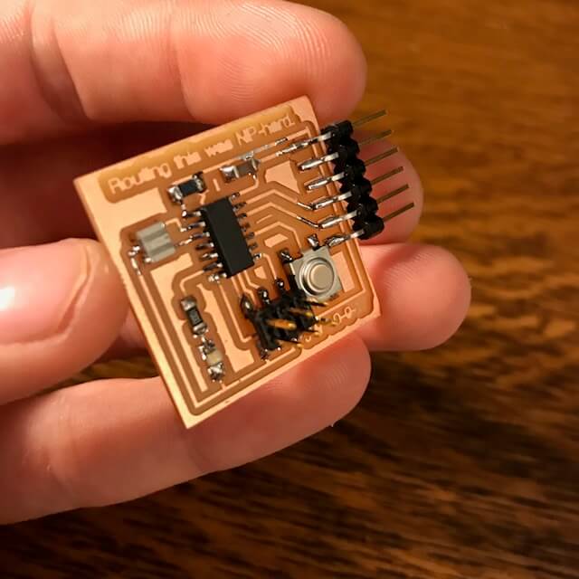
And then I got going. To summarize the work I did… the Hello, World design can be found here and here. Beyond that, I unoriginally added a subcircuit containing a LED controlled by a button. Actually, this was all routed through 2 of the 14 GPIO pins in the ATtiny44. So the button sent a bit signal to one of the pins, which was read by the controller and which was in turn was written to another of the pins, ultimately triggering the LED. Overengineering at its absolute finiest. Still, this was a worthwhile exercise for the first time around.
EAGLE is an awesome tool. I was shocked to find it is in fact 30-year old software. It has a scriptable GUI for simple schematic design (wiring up components into a circuit)  and another for routing (shifting the wires into actual PCB-amenable routes)
  .
.
While I’m sure I’ve broken a handful of best practices in this Hello, World stab at EAGLE, here’re the schematic and routes for the schematics I went with:
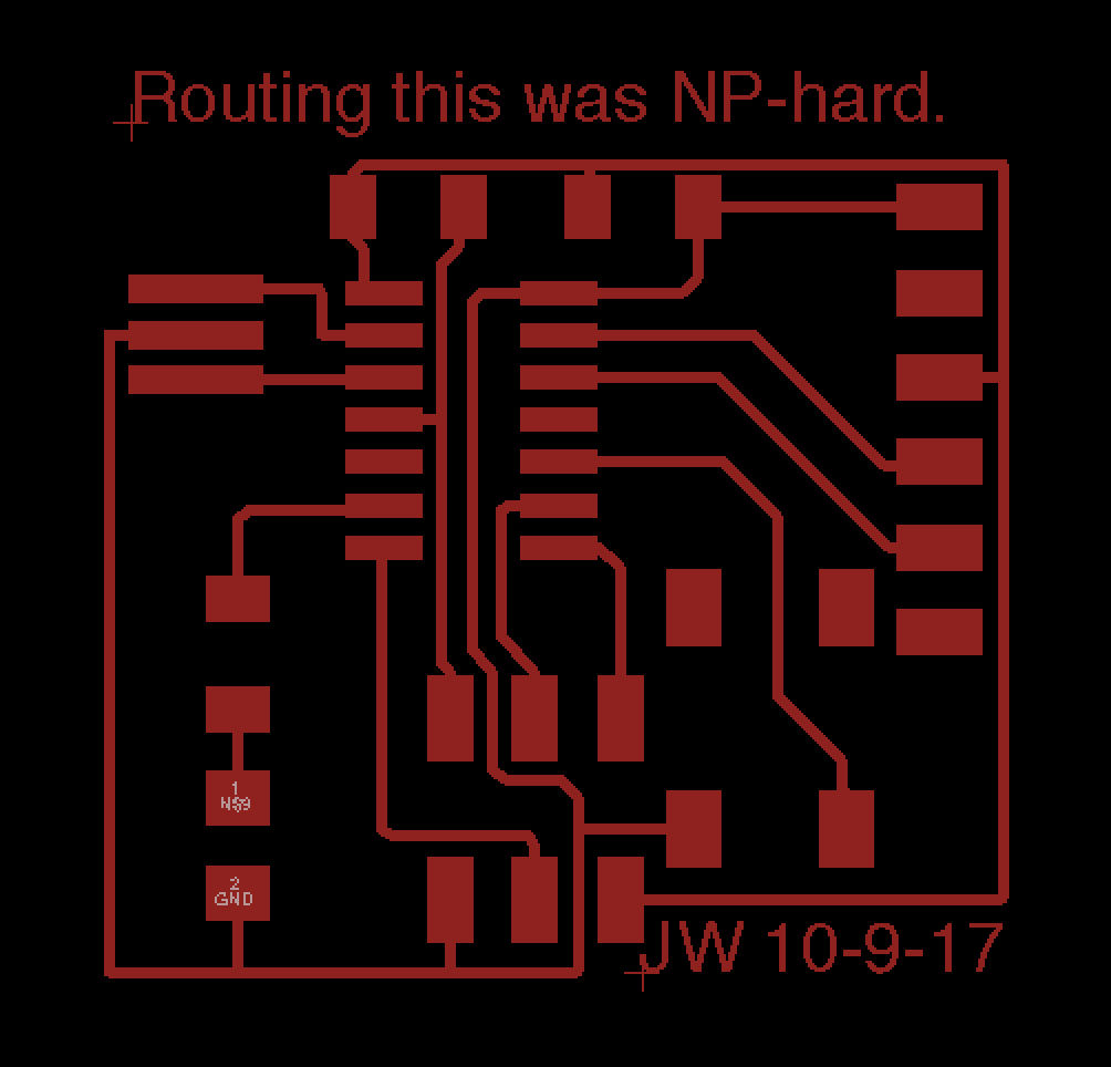
Above (right): .brd file in EAGLE
From here, I walked through the same PCB steps as before (class, blog), arriving at the same zen-like while soldering :)
We weren’t doing any interesting programming in particular, so for the sake of time I’ll hold off on the programming piece that allowed the button to control the blue LED (woo!).