Assignment: Make an in-circuit programmer by milling the PCB.
This week’s assignment didn’t really involve a creative component: it was about learning electronics production skills to build a programmer that someone else has already designed. So at this point, I don’t fully understand what I’ve built.
PCB Milling
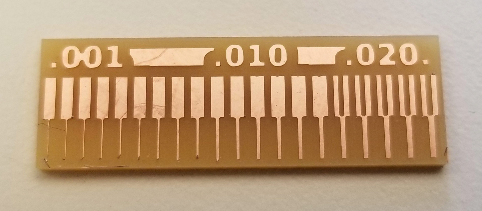
First up was milling the PCB from FR1. I did this on the Roland MDX-20 mill. Before making the actual PCB, I made the characterization test board with Chastity Li and Jordan Kennedy. It worked! As expected, the 1/64” endmill was unable to get between the lines where it was narrower than the diameter of the mill.
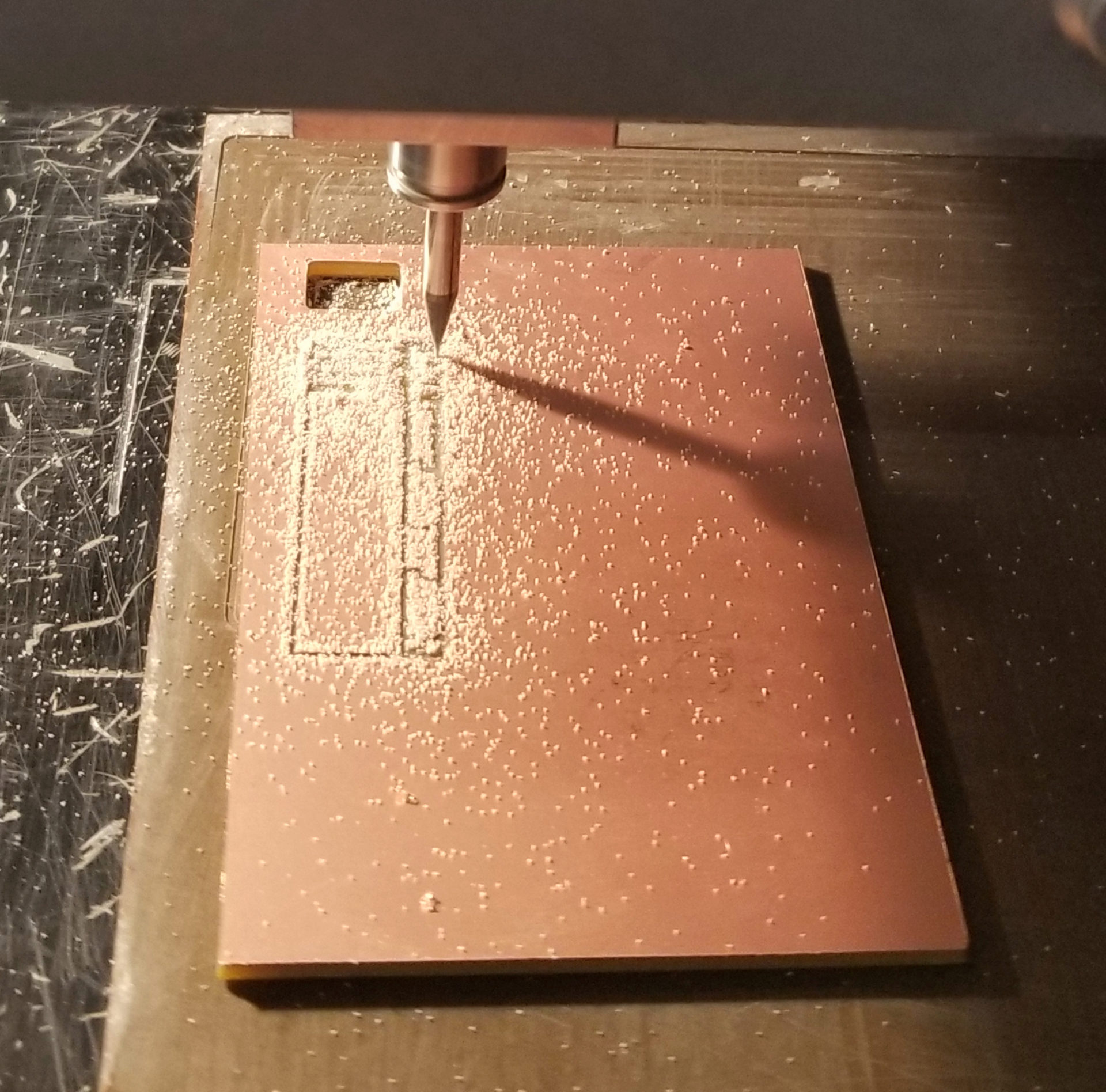
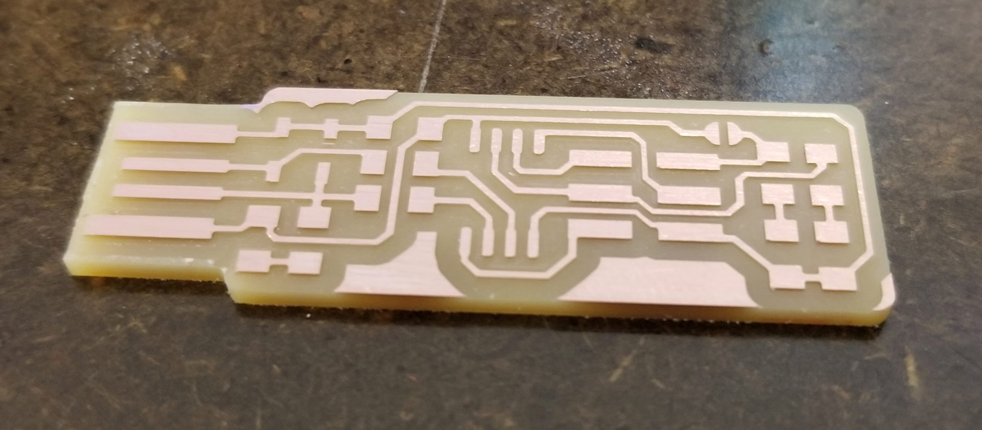
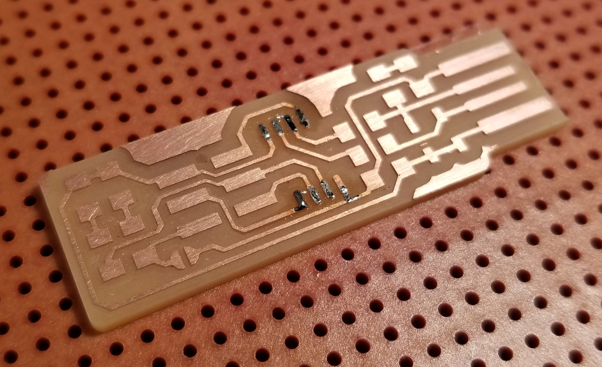
Now it was time to mill the PCB. And here’s how the traces turned out:
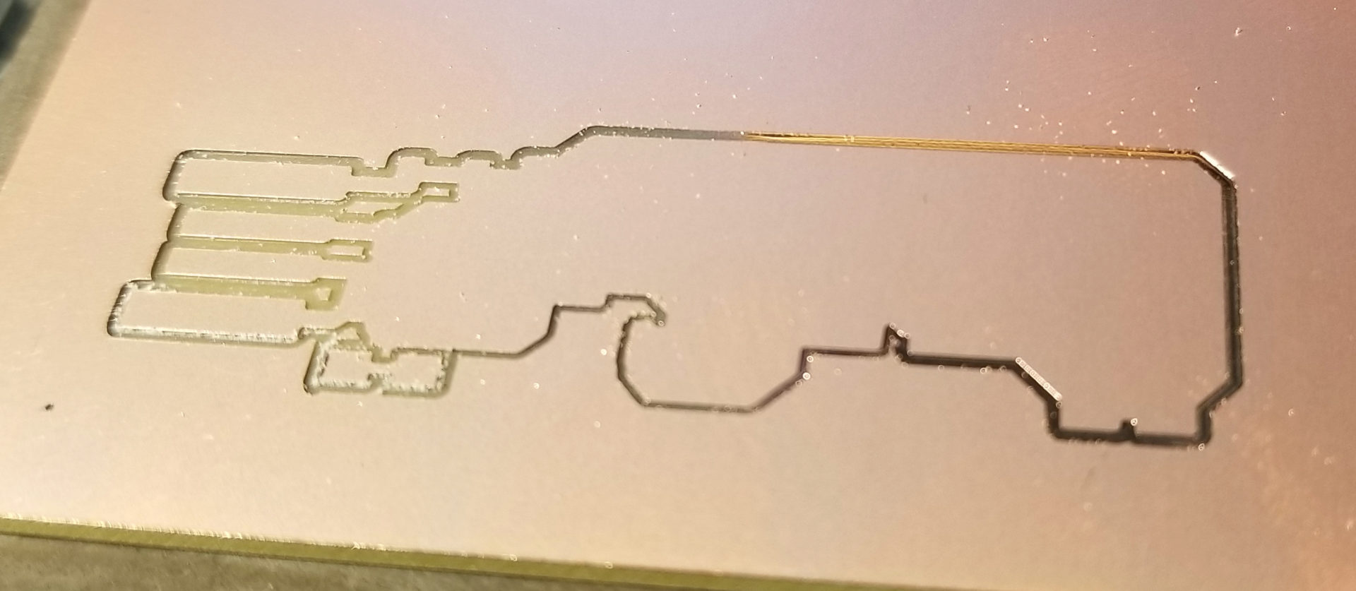
I ended up stopping it at this point to save myself time, because it clearly wasn’t working. It was cutting all the way through the copper on the left, but not on the right. It turns out this was entirely my fault. When I taped down the board, I had ended up putting it ever so slightly over a lip on the edge of the sacrificial layer:
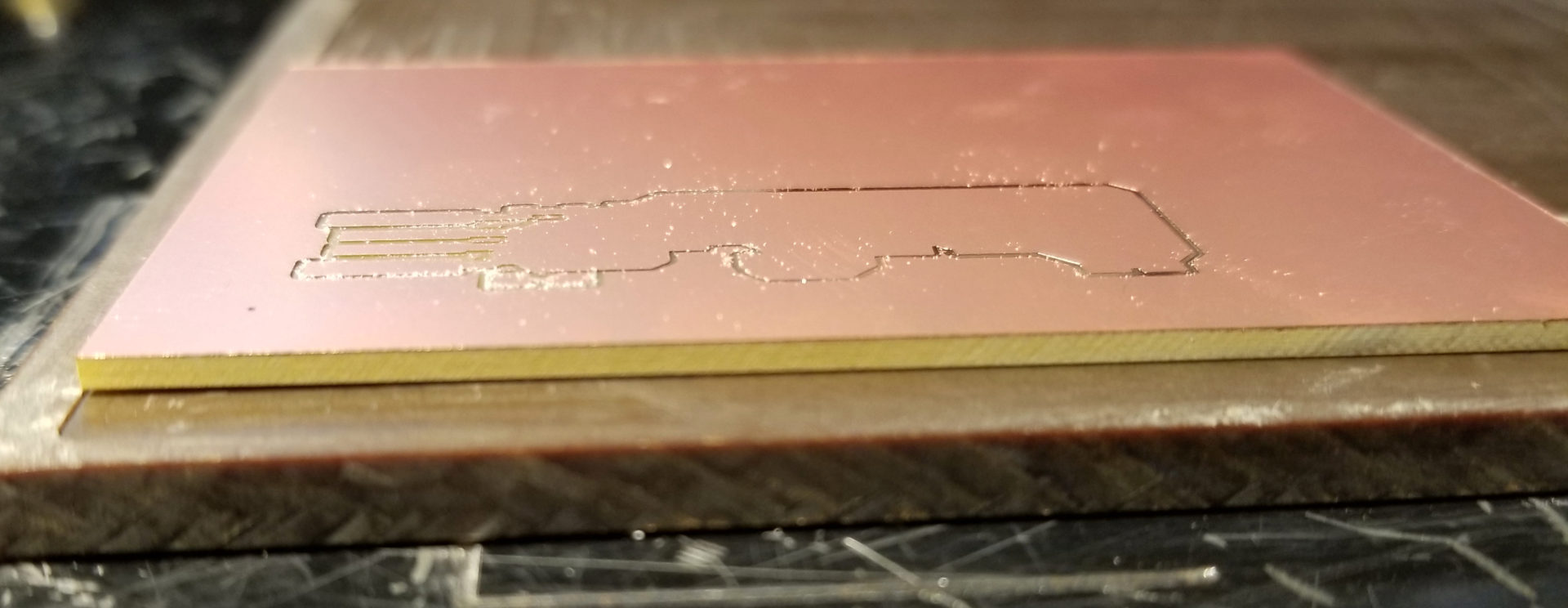
I wouldn’t have noticed unless my milling failed. But this also demonstrates just how thin of a layer the mill is taking off. Dixon also suggested adding more tape to the bottom of the board in the future to make sure it’s fully, flatly adhered to the sacrificial layer.
I moved the board over and tried again. On this second go, the traces all came out perfectly. Instead of the default 4 offsets, I had increased it to 7. I figured this would reduce the likelihood of my putting on too much solder and and accidentally connecting parts. It also reduced the amount of trimming of excess copper I had to do on the USB connector. I also ran over the whole thing with a scotchbrite pad, since there were sharp little nubbins of copper on the edges of the traces.
Soldering
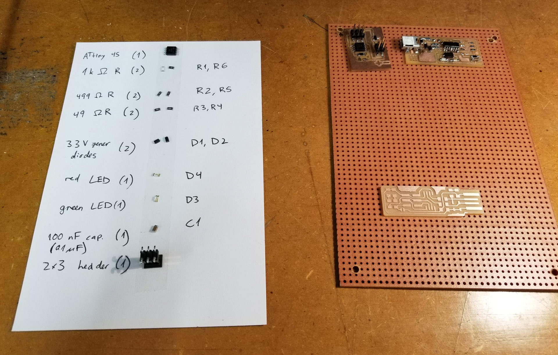
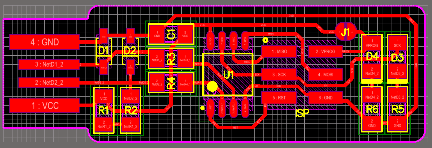
With a shiny new board, it was time to solder. I washed my board with soap and water and tried it. I also gathered and labeled all of my components on a note card, per Rob’s suggestion. These parts are absolutely miniscule! Without sticking them to double-sided tape on the card, it would have been impossible to keep track of them. (As it was, I still managed to drop a resistor, which is now forever lost on the floor of the lab.) I also labeled them to match the diagram to make assembly easier. And in further praise of double-sided tape, sticking my PCB to a larger board made it a lot easier to handle, since it didn’t slip all over the place.
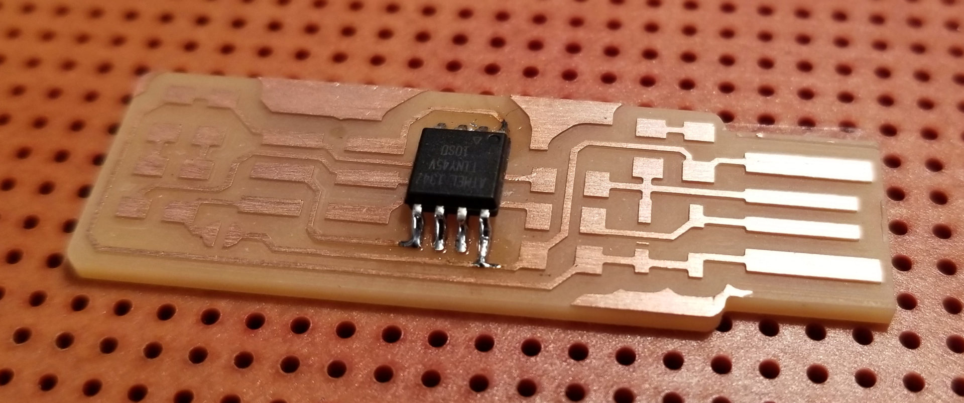
I started with the microcontroller, which has tiny little pads. I’ve soldered before, but on much larger things – breadboard scale (or more precisely, in my case, robotic lobster scale). The transition to SMD parts was not as hard as I expected; it was mostly about keeping the part where I wanted when sticking it in place on the PCB. I was super pleased with how nicely it turned out:
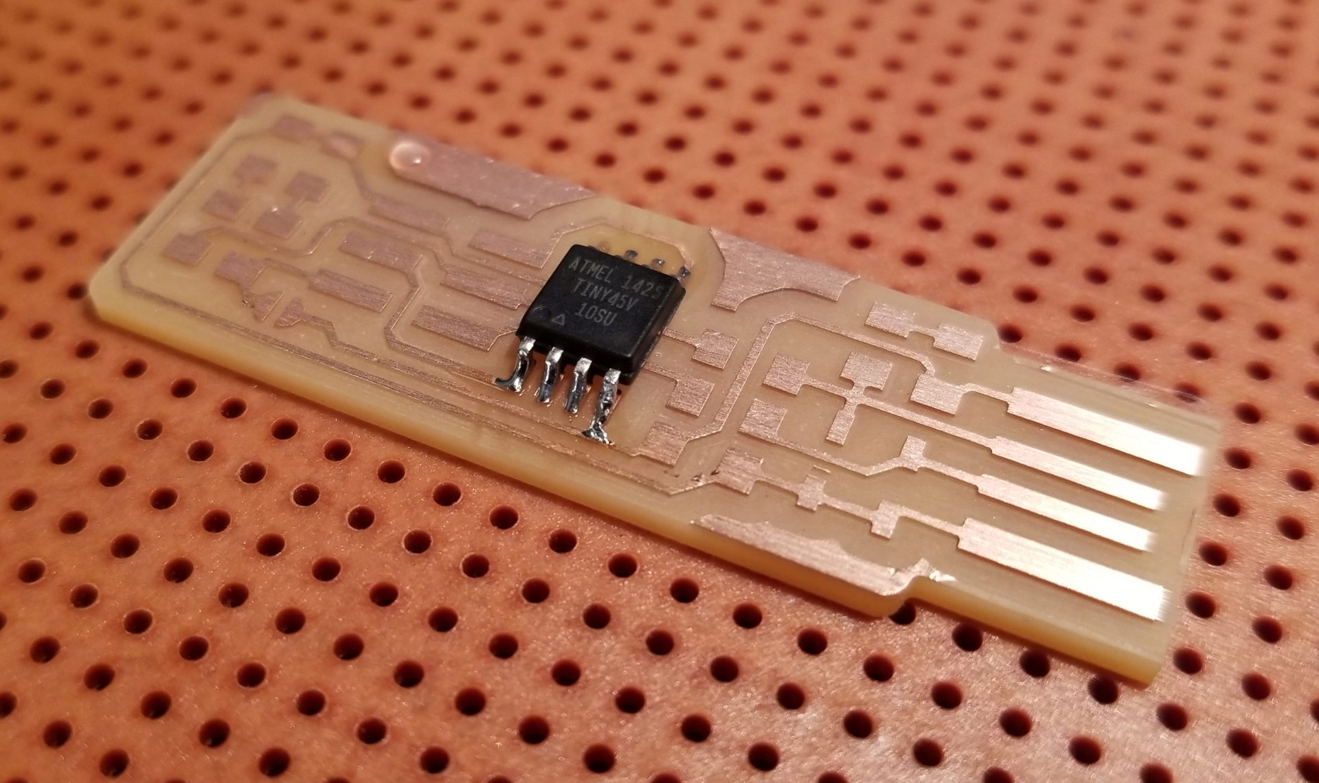
… Except that it’s upside down. When I lined up the circle in the lower left corner, I had the whole board rotated 180 degrees. But that meant a chance to practice removing components with the heat gun and excess solder with the braid!
The real challenge turned out not to be removing the microcontroller, but putting it back on. Between the solder left on the feet and the pads, it was nearly impossible to get it to line up when I put down a little dab of solder to get it stuck. It also turns out that the solder braid is not the magic cure-all easy solder removal that I had been led to believe. My attempts to remove it with the solder braid just seemed to make everything worse; I ended up with solder between all the pins. At some point I decided to cut my losses and just solder on a new ATtiny. That worked so much better.
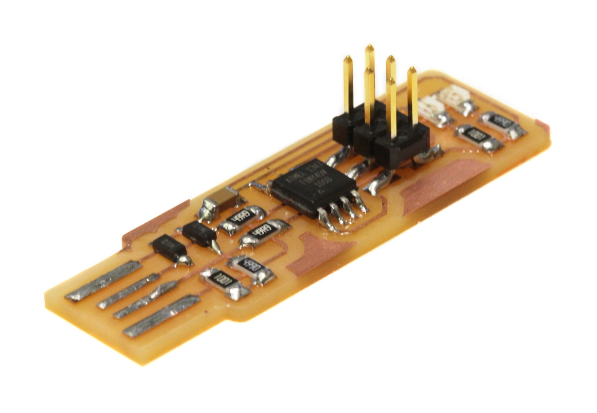
From there, I added on the rest of the components. I started by making the exact same mistake I just had and put my R6 resistor on the wrong end of the board. I also got the hang of this tiny-scale soldering as I went. I discovered that if you use too large of a solder dot to initially adhere a part, it likes to slide around when the solder is melted. I also learned that it’s incredibly hard to precisely align surface mount parts after you’ve had a large cup of coffee; those shaky hands seem way more obvious. As I went, my joints got shinier and smoother. I was paranoid about adding too much solder and having it flow over to other traces and short out the board or something. It turns out that the surface tension along the edge of the copper is pretty strong. In fact, it turned out to be pretty difficult to even connect the J1 jumper, since it kept turning into two little blobs when I took away the soldering iron.
I’m really pleased with how the final product turned out. Before plugging it into my computer, I got a postdoc in my lab to help me test for any shorts on the board and got a clean bill of health.
Programming the Programmer
Programming the board was slightly more confusing than I expected, but mostly since the directions were unclear. When you’re programming a programmer, it can be tricky to keep track of what board or programmer the directions are talking about. I started with these instructions but ended up needing to do a little trial and error to make things work, along with help from Rob:
- Plug your in-progress programmer into a USB extension/port. The red LED should turn on. (In my case, the connection was really finicky and I had to wiggle it around to get it to stay lit up.)
- Also plug your programmer into an already-functional programmer via the 6-pin header. (To work with the compiled version of the firmware, this should be a fab-made programmer, not the Atmel one or something else.) The pins have to line up here. In the case of all the fab-made programmers, the #1 pin is always on the bottom left. The already-functional programmer should also be plugged into the computer via USB.
- After unpacking the firmware, run
makeand thenmake flashto send the new program to your in-progress programmer via the already-functional programmer. - Run
make fusesto set the fuses on the in-progress programmer. - Unplug the already-functional programmer and check that the in-progress programmer is detected on USB using
lsusb. The in-progress programmer should show up asMultiple Vendors USBtiny. - Now de-solder the jumper on the in-progress programmer.
- To test your new programmer:
- Find a different programmable board to test your programmer with. Plug it into a USB power supply (instead of the computer, so the computer doesn’t get confused).
- Connect the programmable board to your programmer via the 6-pin header.
- Run
avrdude -c usbtiny -p t45, and it should give a response that you are connected.
When I tried this, I made two significant mistakes. First, I tried using the Atmel programmer that was sitting next to the computer (and of course, when I tried to run make flash it threw a bunch of errors at me.)
Second, when testing my new programmer, I misinterpreted connecting it to a “working board” as Rob described in his instructions. So I still had it connected to the already-functional programmer. This meant that avrdude -c usbtiny -p t45 threw errors, because it couldn’t connect and program a programmer. When I connected it to the board meant to be used for this test, it worked just peachily. When I connected the programmer, the red light lit up (getting power), and the green light flashed based on the signal sent by the connected board.