Assignment: Measure something: add a sensor to a microcontroller board that you have designed and read it
This week we’re back to things I can use for my final project, and that I now have time to do.
I have a couple of specific goals for this week:
- Use a phototransistor to measure infrared light:
- Whether or not there’s an IR light shining
- How fast the light is moving (I don’t care about the direction of movement, but I may still need a second sensor depending on how well the phototransistor works for this)
- Can I detect flashes of IR at different frequencies (e.g., 10 times/second, not varying the frequency of the light)
- Put a bootloader on my board to try using it with the Arduino IDE and libraries
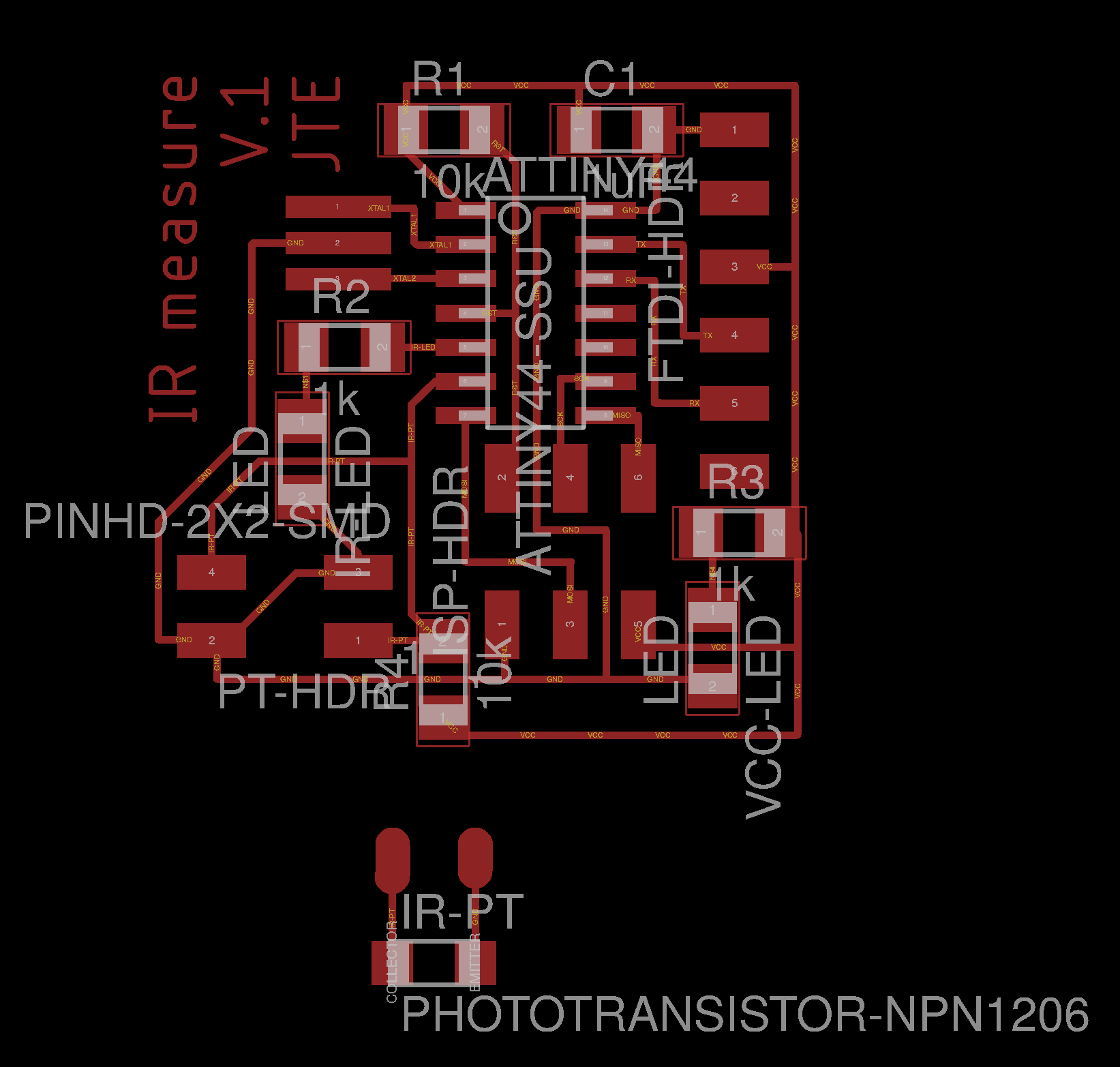
I started with my Hello World board design from Week 7, and started adding things. I put in a power LED like I did two weeks ago, for a sanity check. Then I added in an infrared LED an a 4-pin header to connect to a mini board that I can put my sensor on. This lets me have both the LED and sensor controlled by a single MCU board for debugging and pretty closely matches what I plan to have on the robot for my project: the PCB will be mounted on the bottom of the robot, but the IR sensor will have to be threaded through to the top surface of the robot.
Make the Board
Just when I thought I’d gotten the board milling down smoothly, this week it took three attempts to mill my board.
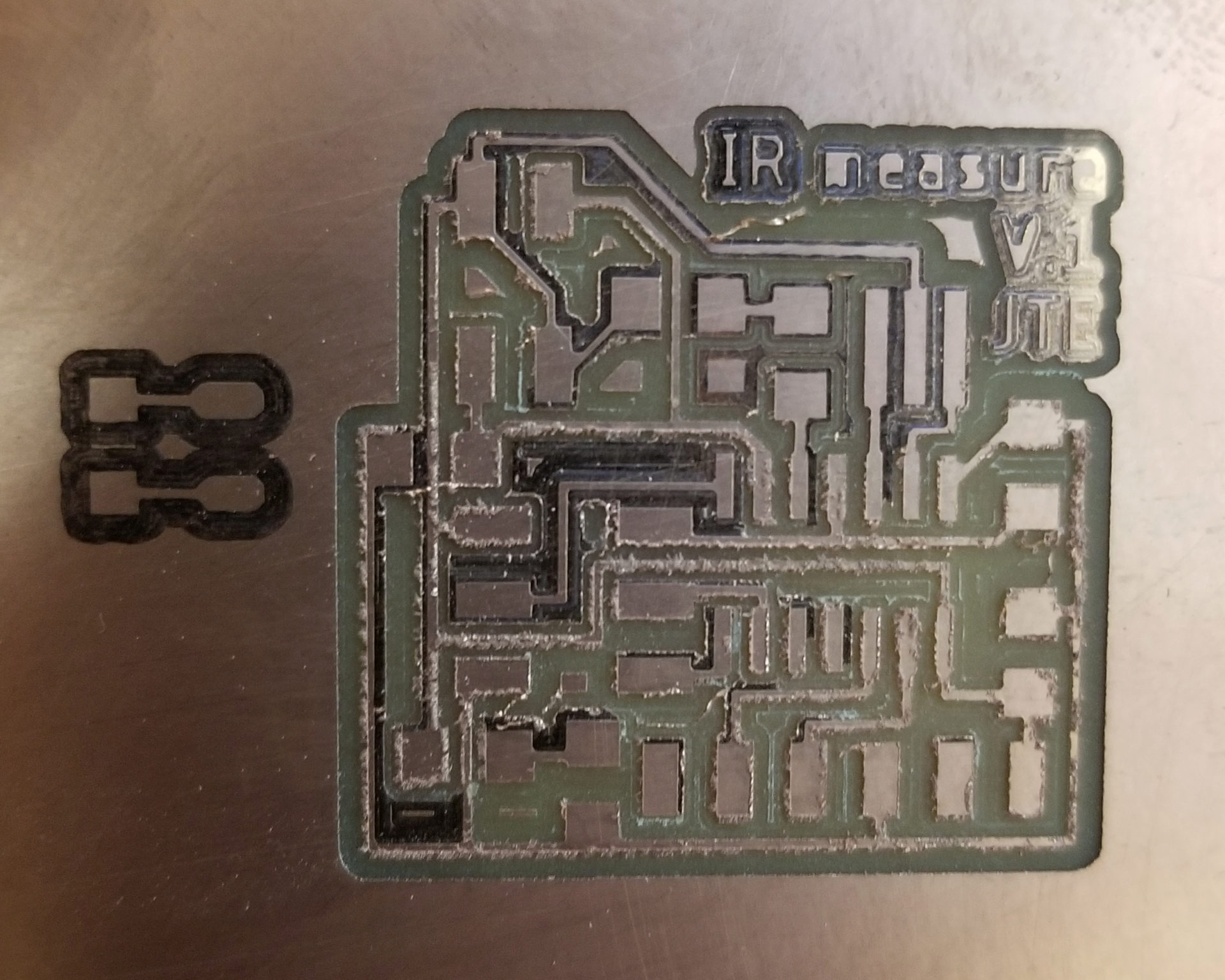
The first time around, I cut my traces and they looked terrible. A bunch didn’t even cut through the copper layer, and where it did the edges of the cuts were really rough. My guess was that the endmill was dull. Turned out I was right; I swapped out the endmill and the traces on the second board came out fine.
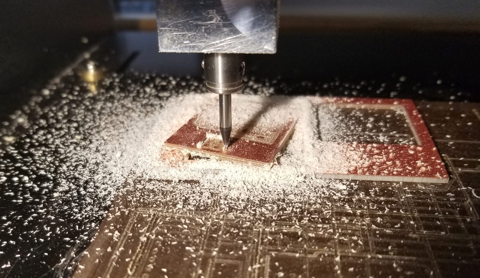
The second time around, things went haywire when I cut the outline. When I’d exported the image from Eagle, there were some weird extra white lines. But I was too lazy to edit the image to get rid of them. It’ll just create extra cuts, I said. It’ll be fine, I said. I lied. When it went to cut out he sensor mini-board, it had already milled a larger rectangle around both boards. So there wasn’t enough tape holding down the board and the mill pulled up the board. Oops.
But third time was the charm! I relented and cleaned up the extra lines for the board outline in Paint (we’re keeping it high tech here).
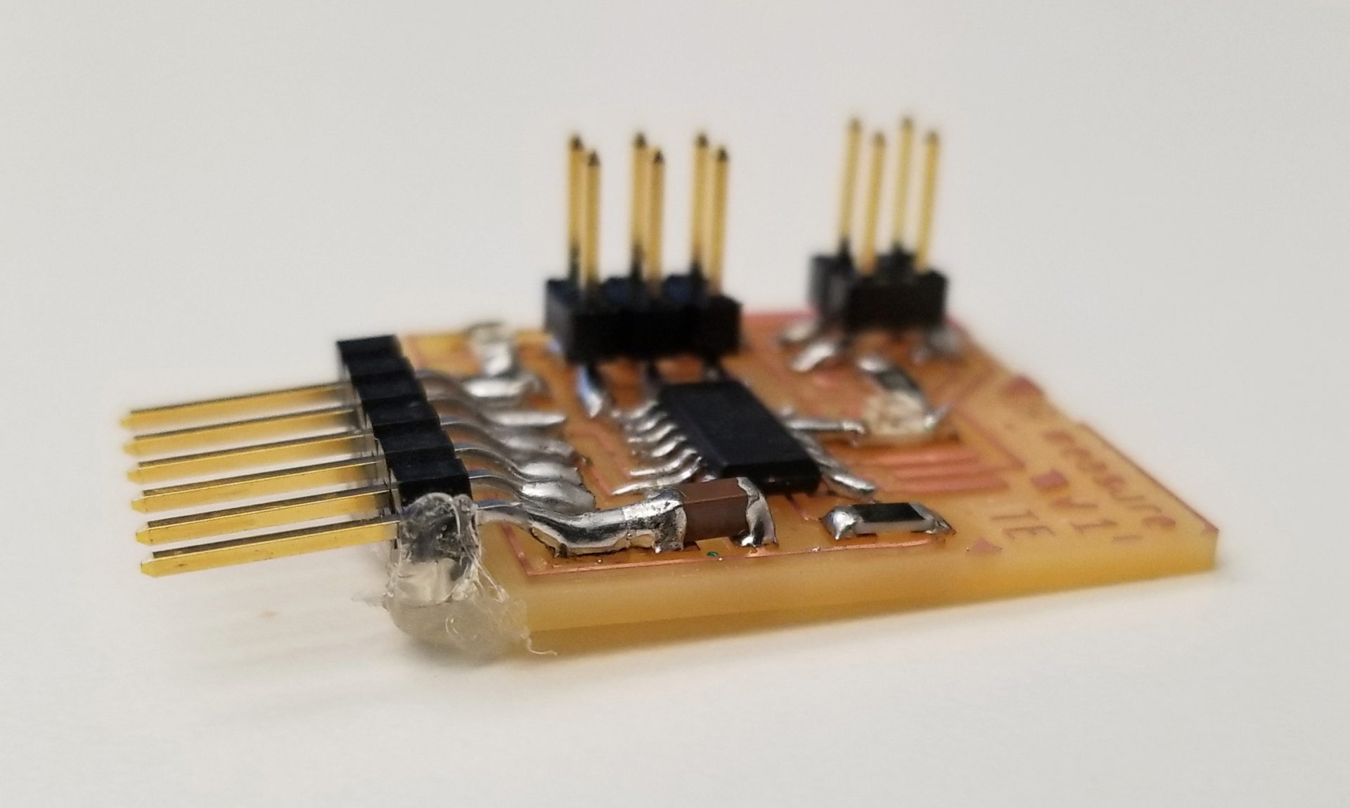
When it came time to stuff my board, I realized that in my effort to make a super compact board (which I’m getting better at, by the way), I hadn’t left much overhang to support the FTDI header. Solution? Stuff a bunch of hot glue under it! (Side note: that mega-joint between the capacitor and the FTDI ground pin did in fact start out as two separate solders.)
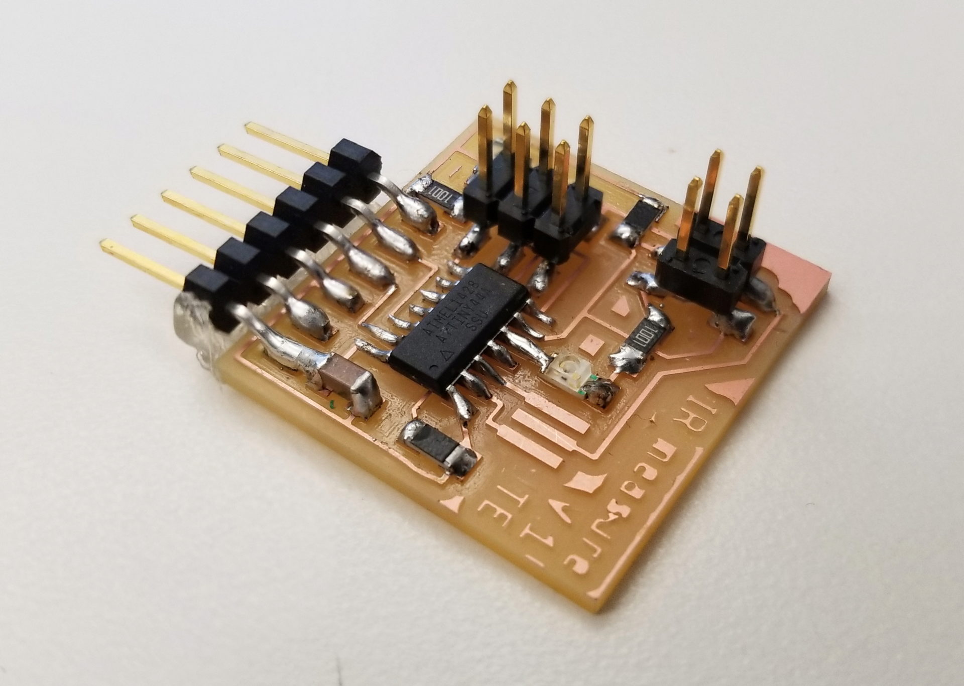
When picking the parts for my board, I also discovered that we were out of 20 MHz resonators. I told Rob so wee could order more, and for this board I just left off the resonator altogether and hoped my clock was close enough to work for serial communication. (Spoiler alert: it was.)
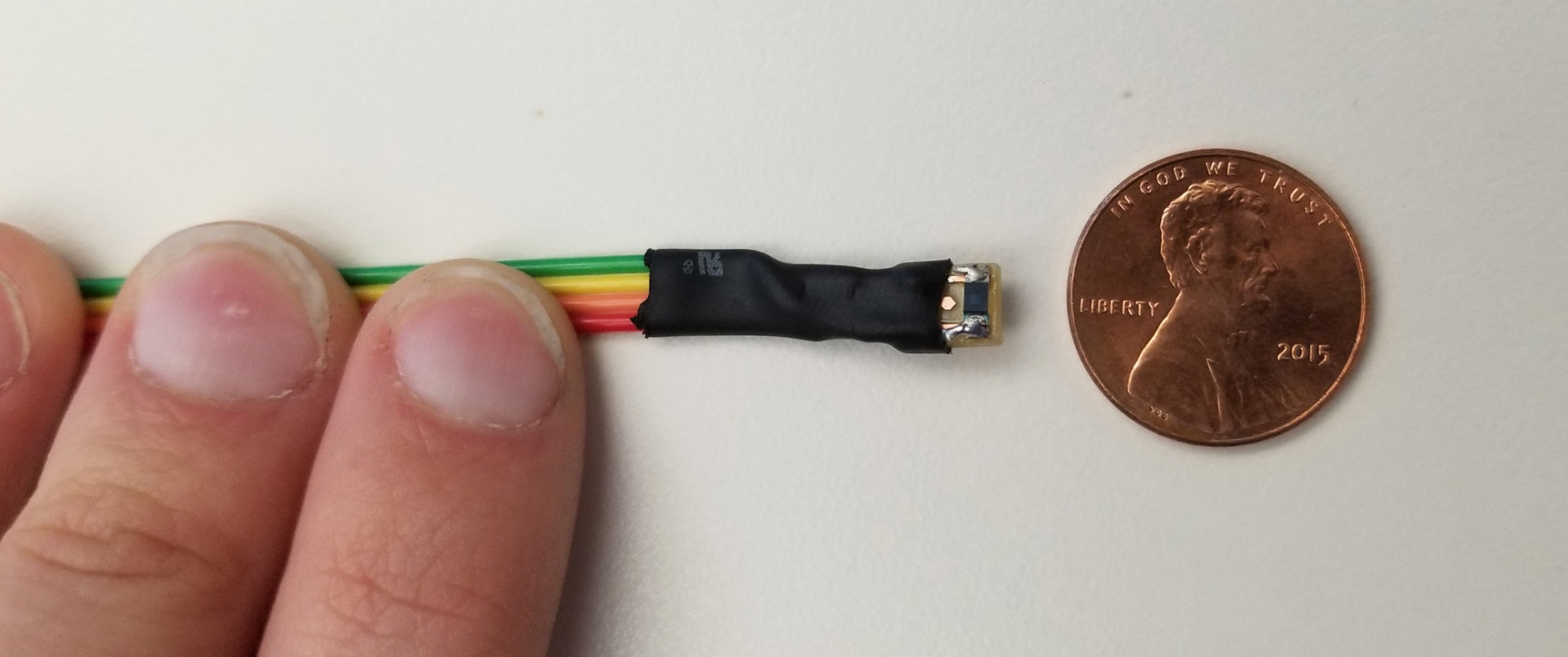
I’m weirdly proud of this tiny board for my phototransistor. It just has a single sensor on it, but somehow it manages to look cute. I connected it to a probably-too-long cable and a 4-pin header. The diagonals of the 4-pin header are both connected together and to one of the connection on the mini-board, so that there are only two orientations for this to be connected to the board. (That increases my chances of getting it right from 25% to 50%!) I also heat-shrunk the connection between the wires and the board give it some structural integrity.
Program the Board
I started with Neil’s Hello World Program for light sensing (C code, Makefile, Python interface). I then modified it to use the right pin for my FTDI header and added a section to turn on my infrared LED.
The challenge came in adapting the code to work with the ATtiny 44(which I’m using) instead of the ATtiny45 (which the example code uses). For this, I dug into the analog to digital sections of datasheets for both boards. I had to figure out what I needed to do to the ADMUX register to make it work the the 45 and my pin. Once I figured out what each of the bits in the register meant, it was pretty straightforward to set them.
I have my modified code here: C code, Makefile
Testing the board
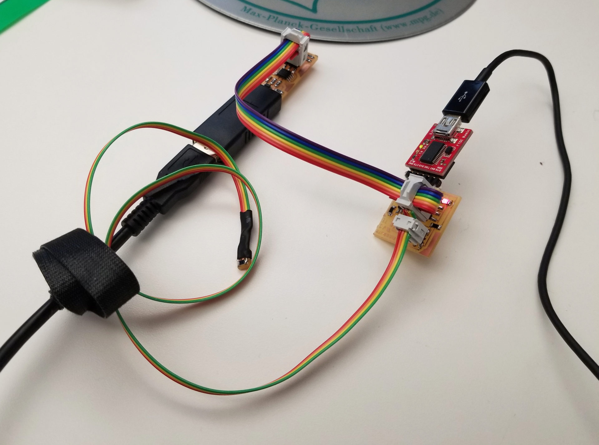
I didn’t actually know which end of my phototransistor was the collector and which was the emitter. There were tiny marks on the ends of the IC, and I checked them against the datasheet for the part, but then I realized it didn’t really matter. Because there are only two orientations that I can connect my 4-pin header, if it didn’t work I can just rotate it 90 deg and try again.
The moment of truth: plugging it in and starting up the Python serial receiver on my computer. At first, I thought I’d seriously screwed something up: I was getting a reading of 1023, but when I squeezed the miniboard, it went down to 800-something. Had I somehow magically created a force sensor instead of a light sensor? Nope! My confusion came from the fact that the value goes down when the light gets brighter, since more of the voltage goes through the phototransistor when that occurs. As for the force-sensing part, my guess is that when I squeezed it, some of the current was going through my fingers to connect the pins on either side of the sensor; it had nothing to do with my sensor at all.
First I looked at how it sensed my desk lamp. It was almost too good; apparently that light puts out a lot of infrared. It made me a little worried about how much bright background lights might end affecting the readings on my robot. But as long as no one shines a flashlight on it I’m probably fine, since when my sensor isn’t right under my desk lamp it still reads 1023 (no IR light).
Then I tested it with the infrared LED I had installed on my board. The phototransistor did detect it, but it had to be really close to pick up a change.
I realized that the problem was likely that I was using too large of a resistor, so the current through my LED was really low, and therefore the light was too dim. So how bright could I get the LED and not blow it up? According to the datasheet for the LED, it has a maximum forward current of , which on its IV curve matches to about . If I want going through my LED and I have of power, I need the remaining to be absorbed by my resistor. Recalling , this means I need a resistor of about . The easiest was to approximate this was to put in parallel a breadboard resistor that was laying around the lab. (In parallel with a large resistor, the resistance is pretty close to that of the small resistor because the current will take the “easier” path.) It was tricky to hold this resistor in place while moving the sensor board, so unfortunately I don’t have a video of this improvement because I don’t have a third hand. Suffice it to say, it worked; I has able to get mid-range digital readings (500-850) out of the sensor when it was 5-10 cm away from the LED. This is great, since that’s about the distance between my robots when they’re stacked on top of each other. I was also able to see a clear spike when I moved the light horizontally across the sensor, which means that robots should be able to easily detect the movement of robots on top of them.
I just said easily, so I think I jinxed it; my concern here is that the horizontal range for sensing is pretty limited, meaning they wouldn’t know that there’s a robot on top of them. The solution would be to add more sensors or more LEDs, but I’ll hold off on doing that until I have a better sense of the robot design and what modifications to make on that front.
About That Arduino Stuff…
I once again didn’t get around to making my board work with Arduino code. But I at least made progress this time. Rob directed me to this High-Low Tech page that walked me through setting up an ATTiny 44/45 to work with the Arduino IDE and program it with the FabISP. Over Thanksgiving break, I’m hoping to get this working as an alternative to hanging out with family. It looks like I need to load the programs with the FabISP each time; it doesn’t actually put on a bootloader. Can I get a bootloader if I switch to the ATMega328p? Trying out that microcontroller is another thing on my TODO list.