Tried to make a board I would actually use for my final porject this week. Took the stepper motor board and added a 4pin connector to later add a light reflection/proximity sensor.
Continuing Prep for Final Project
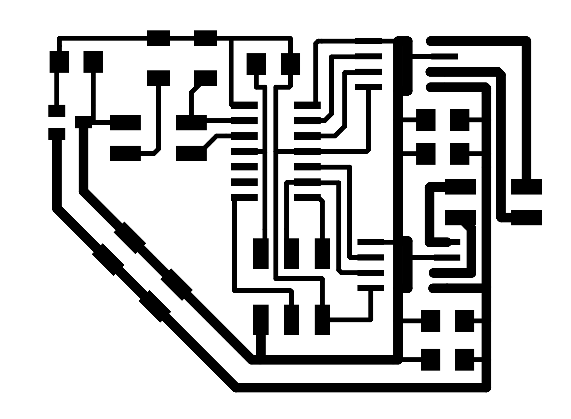
After reading about some of the problems with I2C protocol and ATTINYs, I decided to go a little simpler with just a light proximity sensor for my final project. I will strategically place mirrors on my dining room table and on my wall which hopefully the light sensor will activate when very near them. I will have to make the threshold high so as not to trigger from ambient light. I wanted to design this weeks circuit with an ATTiny 44 and choose ports that would enable me to use the same basic design for the the output this week and allowing me to add an 4 pin input to add the sensor later. Below left is the original sync light input and below right is the stepper motor board. Notes: I used 40mm traces for most paths. I used 50mm for the motor power traces.


Creating the schematic using KiCad
I used KiCad again. Here is a link to a great site that documents the workflow of KiCad. You can see in the top right of the schematic where the sensor will be attached via a pin connection.
Download the full KiCad file:

I used imagmagick again to correctly convert the SVG files to PNG files from KiCad using help from Harvard's TA Rob Hart. Thanks! 1. Creating in Kicad a graphic line around the board on the Edge.Cuts layer. 2. Then export two SVG's from Kicad: First one with F.Cu selected, then one with Edge.Cuts. 3. Convert with Magick: "convert -density 1000 -units PixelsPerInch x.svg x.png". 4. In mods, the traces run as converted. 5. For the outline, invert the image. The tool will take away a tool-width of board - just need to account for this in your design. The edge file needs to be You can download the PNG files here:

Soldering the board
This had a decent amount of components. I am definitely slowly getting better with my soldering. The one trick here was that the H-bridge had a grounding contact with bottom of the component. I put a helathy amount of solder on the pad I created. PLaced the component on top and then heated it up with the heat gun and pressed down. It seemed to work, hopefully, I did not fry the bridge.


Powering the board
I grabbed a four pin connector and connected it to the DC power supply. I put in 9V and 0.5A. The voltage regulator worked! 5V above the regulator and 9V below.


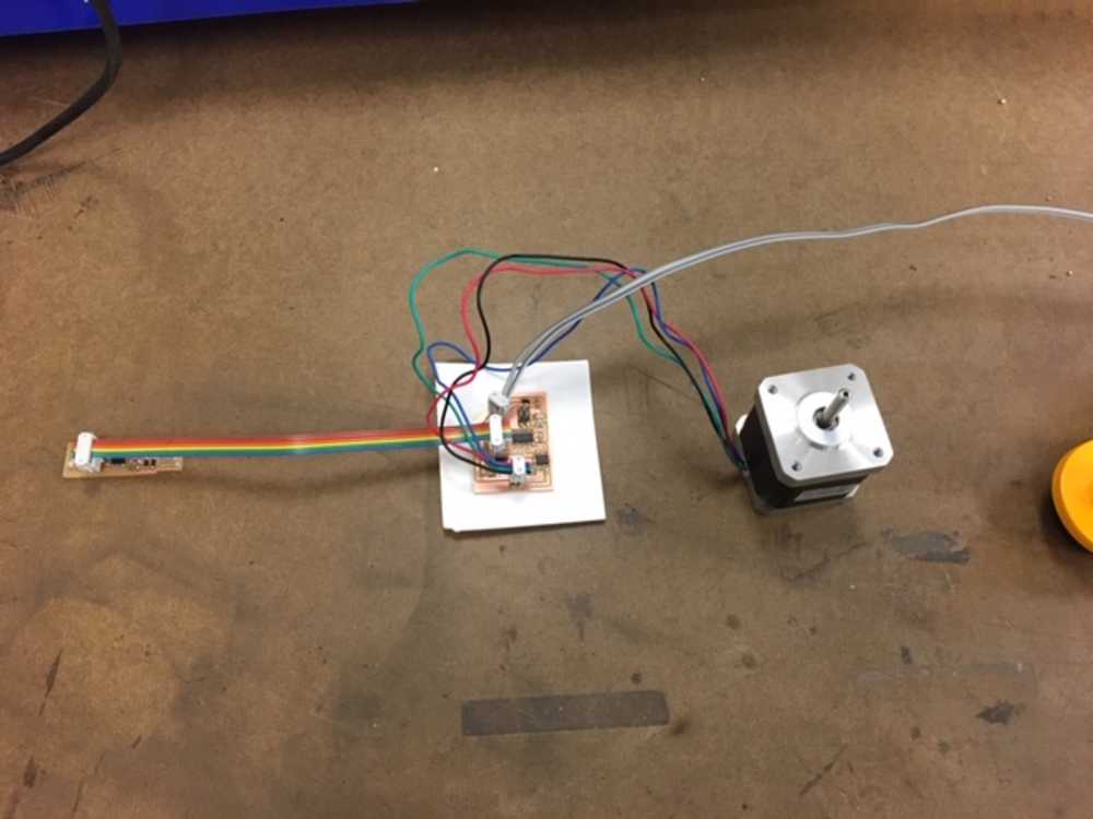
Connecting the motor
Axel was nice enough to loan me a stepper motor for troubleshooting this week. I made a connection for the motor. Becuase it was a bipolar motor, I tested where there was continuity using the multimeter. That confirmed the below diagram - red was with blue, and green was with black.

Programming Fail
After all this, it did not program :/ I used Neil's stepper motor hello world code, since I was just trying to test the ouput this week and the input pins should not have made a difference. I tried both my USB-Tiny and the ATMEL Ice. In case the the open sensor pins might be an issue, I even closed those loops. But no luck. I used the multimeter and it looked like there were no unexplained shorts and all connections looked good. I guess I will jsut have to remill the board. Maybe I did fry the H-bridge? But not sure if that would cause a program,ing failure. Here is the make code and here is the c code
Error screen from the ATMEL ICE
