How To Make (almost) Anything
output devices
MEASURING THE OUTPUT OF VISIBLE LIGHT
TASK
Add an output device to a microcontroller board you've designed, and program it to do something.
LAST WEEK (week 9 - input devices)
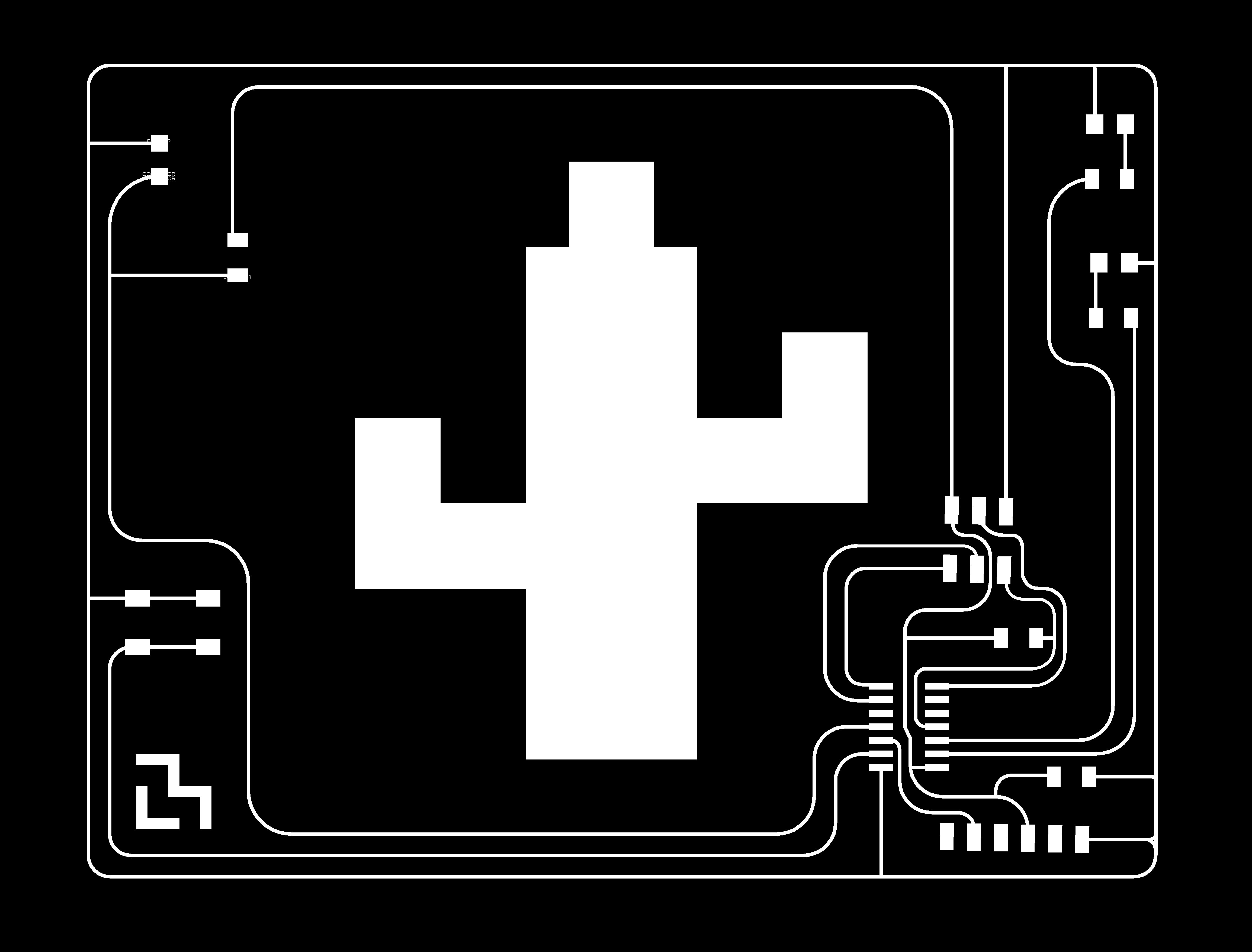
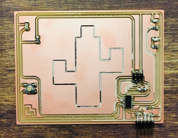
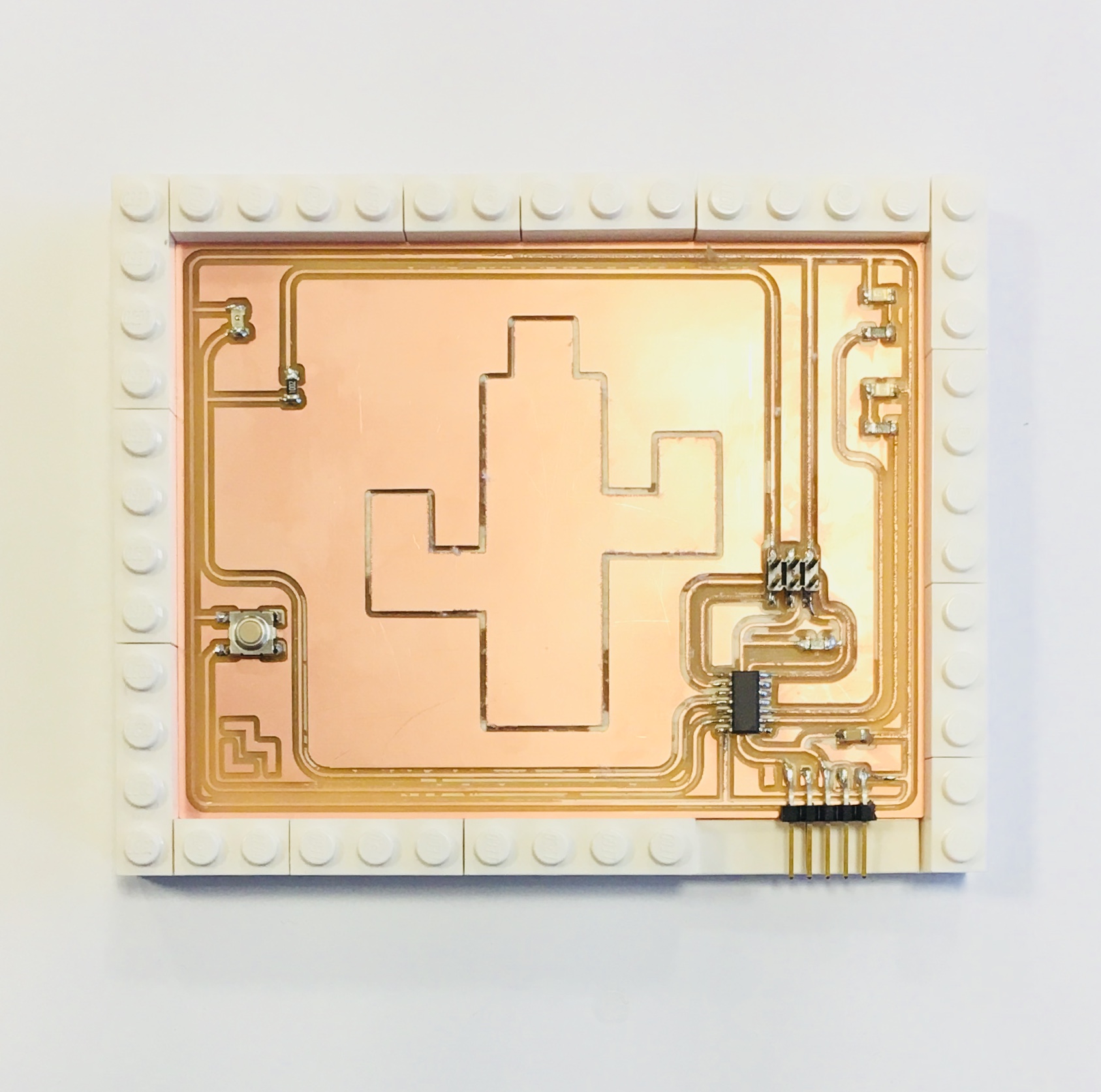
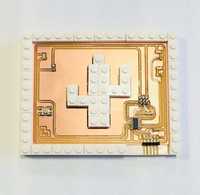
I designed a board with a photoresistor, a button, and 2 LEDs.
The photoresistor measures visible light as the input. The LEDs output light.
THIS WEEK
I programmed the microcontroller to measure light as well as use the button to control the LEDs. I intended to measure how changes in the light output from the LEDs changes the light input measurement from the photoresistor. The button controls the LEDs with 3 settings: all off, one on/one off, all on.
PROGRAMMING
I modified my code from the previous week to handle the buttons and LEDs, and continue to read from the phototransistor.
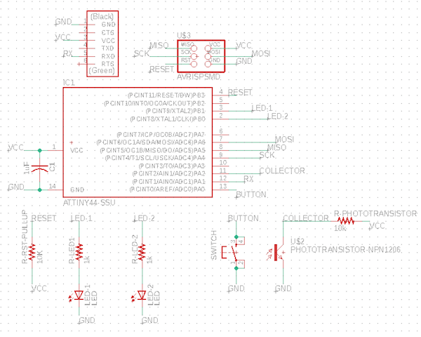
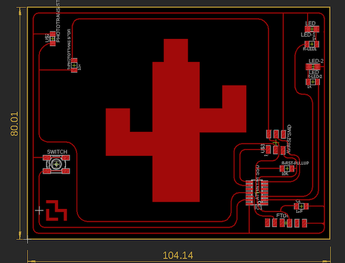
relevant pins:
- (input) phototransistor: PA2/ADC2
- (input) button: PA0/ADC0
- (output) LED-1: PB0
- (output) LED-2: PB1
Step 1:
Set up the additional pins in the code; Disable phototransistor code; Make the press of the button light the LEDs.
Step 2:
Re-enable the code that reads from the phototransistor and integrate the button + LED functionality into the same main loop as the phototransistor.
Microcontroller Code:
Compile the code and program the board with it.
make -f hello.light.44.make
make -f hello.light.44.make program-avrisp2
GUI Code:
I modified Neil’s GUI (written in python) to meet the project’s aesthetics.
python hello.light.44.py /dev/cu.usbserial-FTFMJ6T8
ELECTRONICS UNDERSTANDING
What am I measuring? How does a phototransistor work? What is a phototransistor?
Ohm’s Law: V=IR, where I=current (measured in amperes), R=resistance (measured in ohms)
A phototransistor has resistive properties like a resistor - it limits the amount of current that passes through it in a circuit. When it is exposed to light, its resistance decreases, so it lets through more current, affecting the voltage levels. My ADC2 pin monitors the affected voltage levels, and the microcontroller’s code processes these measurements.
What I am measuring is the voltage observed at the ADC2 pin.
More light:
→ Lower resistance across phototransistor
→ Less resistance between ADC2 pin and GND (V~0)
→ Lower voltage observed at ADC2 pin
This voltage reading is sent in serial messages from the ATtiny to the python code running on the computer. The python code reads in the high/low voltage measurement and projects the measurement onto a 1024 bit scale in order to better visually display the relative light level.
How does the phototransistor sense light?
A phototransistor is a type of transistor.
A transistor is an electronic component made made of a semiconductor material. It exploits the electrical properties of the semiconductor material in order to amplify or switch electronic signals or electrical power.
In particular, phototransistors are made of semiconductor materials that decrease in resistance when exposed to light. This works because the photons excite electrons on semiconductor materials.
Different materials behave differently to different light frequencies.
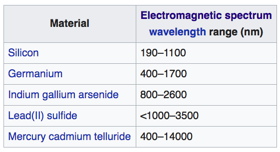
Electro-optical characteristics for the FabLab phototransistor used (from datasheet):
This covers both the visible light spectrum and portions of the IR spectrum:
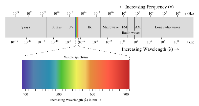
Relationship between light frequency and wavelength: λν=c where λ is the wavelength, ν is the frequency and c is the speed of light.