How To Make (almost) Anything
input devices
SENSING VISIBLE LIGHT
TASK
measure something: add a sensor to a microcontroller board that you have designed and read it.
INTENTION
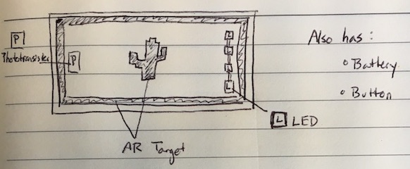
make a board with a phototransistor to measure visible light. The board will also be designed with LEDs and a button to turn on the LEDs in preparation for output devices week, when I intend to measure how the output of the LEDs effects the visible light measured by the phototransistor. I plan to also use the interior design as an AR target later on.
DESIGN
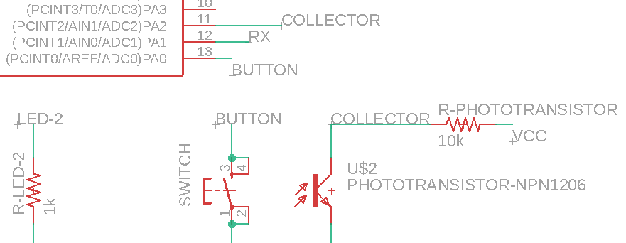
Phototransistors have C(collector) and E(emitter) and are usually placed on boards with a pull up resistor.
Neil provided an example (“hello world”) board with a phototransistor, which I modified. His board uses an ATtiny45. Mine uses an ATtiny44A because it has a few more pins.
Comparing ATtiny44a vs ATtiny45 pins:
ATtiny45 (datasheet)
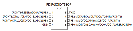
ATtiny44 (datasheet)
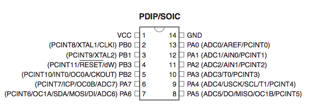
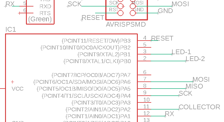
In Neil’s design, PB3 connects to the transistor’s collector, and the emitter is connected to ground. On my board with the ATtiny44A, PB3 will needs to be used as RESET. The transistor just use a pin with ADC. All of the ATtiny44A A pins are equipped with ADC.
When planning my board, I took some notes from Neil’s example board
:- Do not need a resonator/crystal
- Sensor (phototransistor) must be connected to an ADC port
- Do not need a TX connection between the FTDI and ATtiny - only RX. (This makes sense given that the program reads from the phototransistor and does not need to send data back.)
Drawing it out:
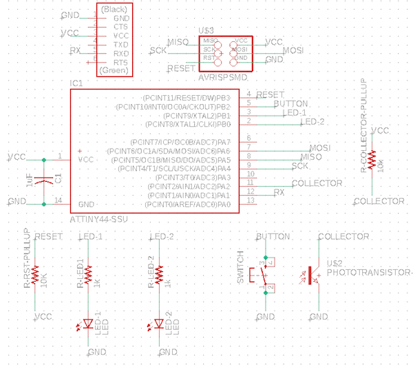
I created my schematic in Eagle.
In my previous experience creating a board with Eagle (week 5 - electronics design), I had trouble routing my board from the schematic. I imagined I would only find the process more confusing this week, with the extra components involved and the aesthetics I had in mind imposing additional constraints. So I decided to first reason about it on paper.
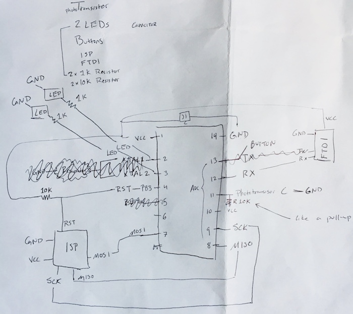
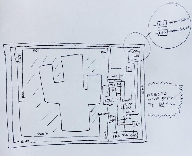
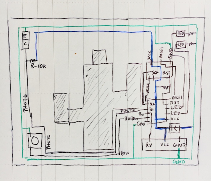
After reasoning about the routing on paper, I realized I should move my button from the B side of the board to the A side (pin 13). I also realized I had missed the resistor for the phototransistor.
I fixed my schematic.
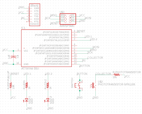
With this and the dimensions of the the intended final product, I layed out my board in Eagle.
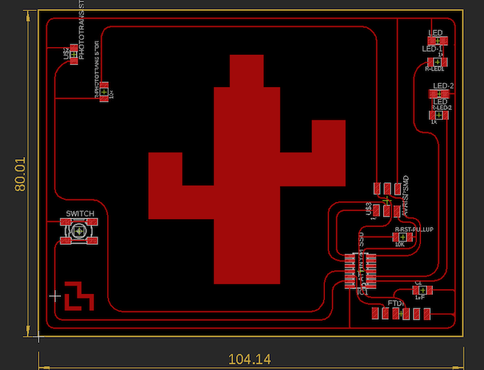
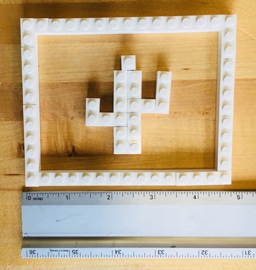
Dimensions of board
There is a lego outline that is 15x12 lego dot units
Each lego unit is 8mm. That means:
- Exterior outline: 120mm x 96mm
- Interior outline: 104mm x 80mm
Exporting the board from Eagle to PNG
A separate black and file PNG file is exported for the board interior traces and the board outline so that they can be cut separately. This is tricky because Eagle is not designed for this.
Following (TA) Sam Calisch’s guidance I:
- Set the window for the board to an aspect ratio similar to my outline. This same window is used for the board outline and interior traces file exports.
- Show only dimension layer:
disp none top → export image - Show only traces layer:
disp none dim → export image - Choose in the export dialog: Monochrome; Resolution: 1000dpi; Area: Window.
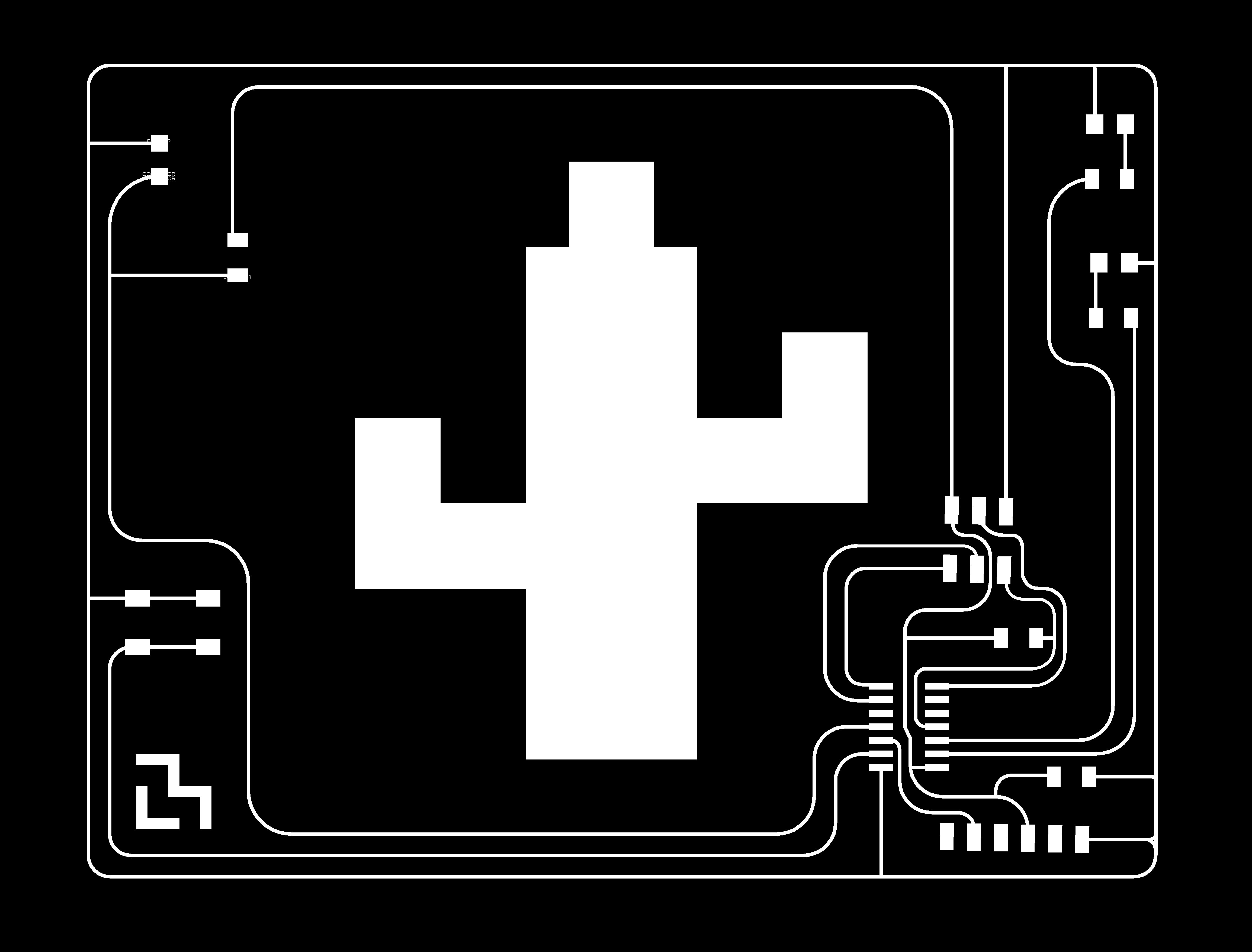

I still needed to touch up the outline image to fill in the interior black space.

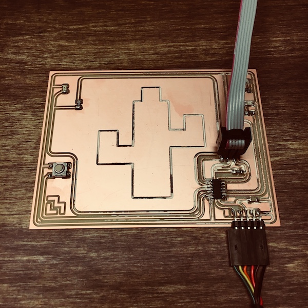
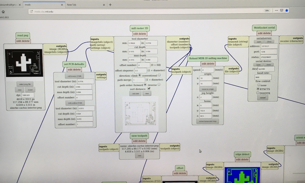
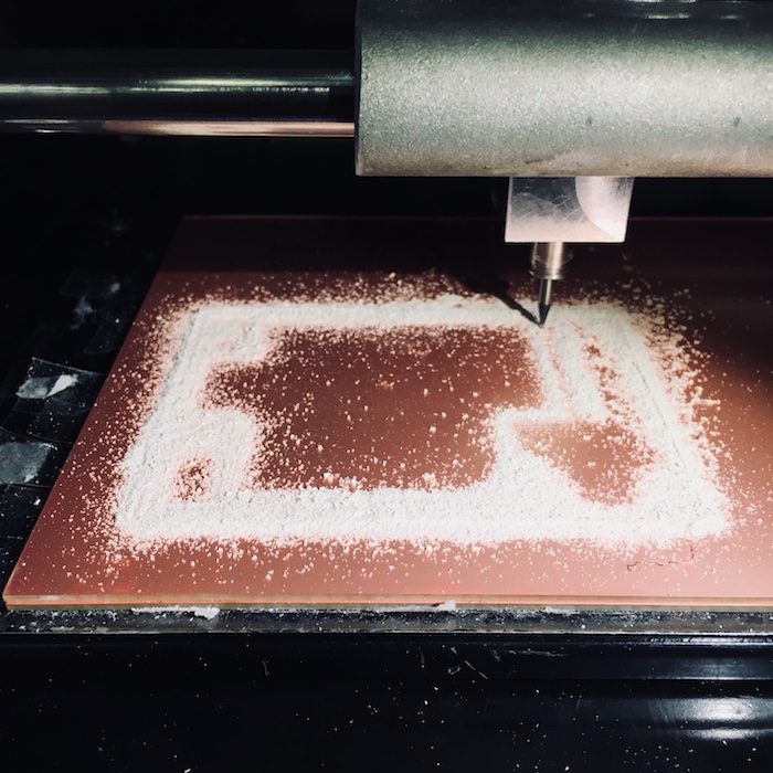
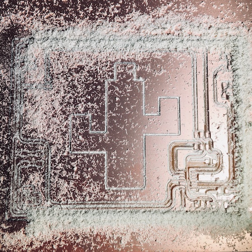
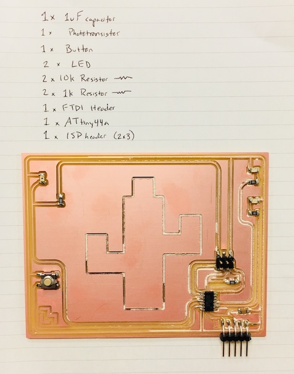
I milled the board using the mods software and Roland milling machine, and then soldered on the components.
PROGRAMMING
Neil provided code for his phototransistor board:
I modified his code to use an ATtiny44 instead of an ATtiny45, and adjusted it for my inputs and outputs.
Input:
His example board connects the phototransistor to PB3/ADC3.
My board connects the phototransistor to PA2/ADC2.
Output:
Neil’s example board connects the FTDI Rx to PB2.
My board connects Rx to PA1.
Compiling the code led to an error.
make -f hello.light.44.make
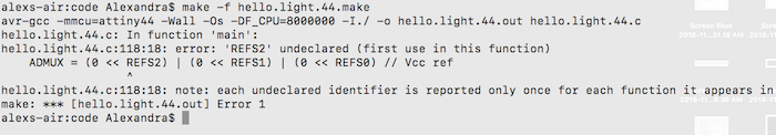
What is REFS2? In the code it is used to set ADMUX - what is ADMUX?
Back to the datasheets...
From section 16.3 of the ATtiny44 datasheet:
The ADC is enabled by setting the ADC Enable bit, ADEN in ADCSRA. Voltage reference and input channel selections will not go into effect until ADEN is set. The ADC does not consume power when ADEN is cleared, so it is recommended to switch off the ADC before entering power saving sleep modes. The ADC converts an analog input voltage to a 10-bit digital value using successive approximation. The minimum value represents GND and the maximum value represents the reference voltage. The ADC voltage reference is selected by writing the REFS1..0 bits in the ADMUX register.
Comparing how the ATtiny44 and ATtiny45 handle this:
ATtiny45- 17.13.1 ADMUX – ADC Multiplexer Selection Register
ATtiny44 - Section 16.13.1 ADMUX – ADC Multiplexer Selection Register
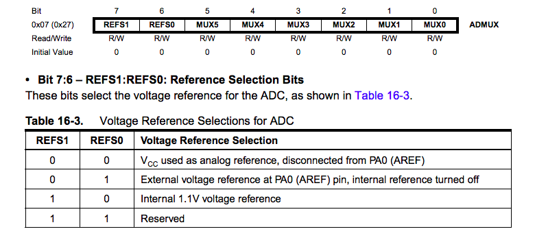
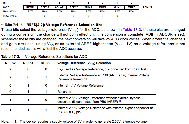
The ATtiny44 does not have a REFS2. So how should I set the bits?
From the ATtiny44 datasheet:
Bits 5:0 – MUX5:0: Analog Channel and Gain Selection Bits
The value of these bits selects which combination of analog inputs are connected to the ADC...
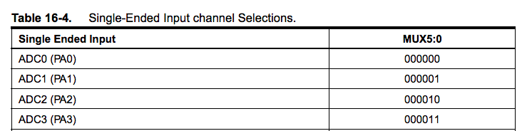
Looking at Neil’s original code I can see it is meant to use VCC as the voltage reference. I updated it to remove REFS2 yet continue to use the VCC as volutate reference, and I updated the MUX bits to use ADC2.
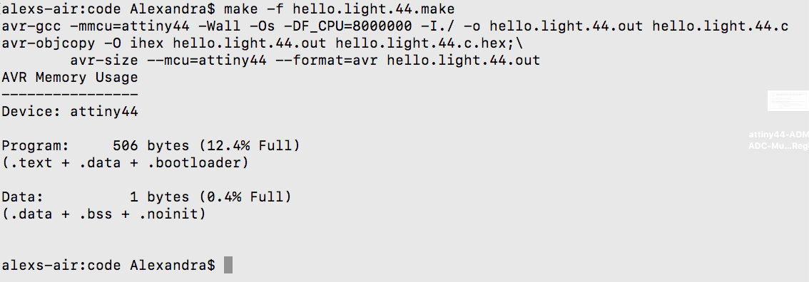
And the code compiled.
Ready...
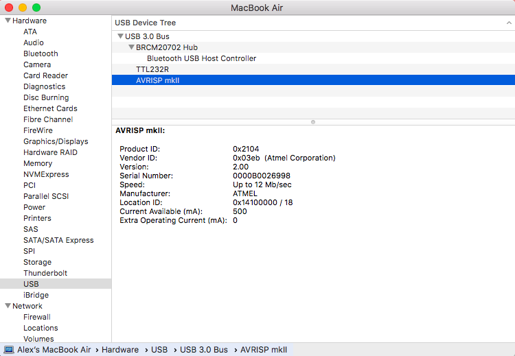
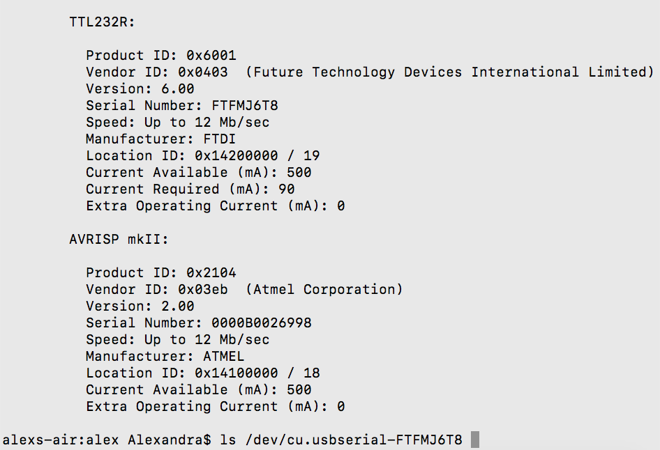
I connected my board to my computer, with the AVRISP2 (the programmer) connected to the ISP header, and an FTDI cable connected to the FTDI header.
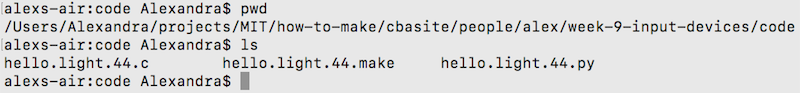
I confirmed that my computer could see the devices and found the location of the port on my computer.
make -f hello.light.44.make program-avrisp2
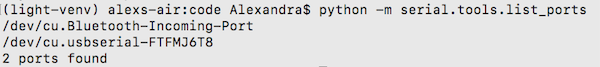
python hello.light.44.py /dev/cu.usbserial-FTFMJ6T8
After debugging a series of errors, I used a python virtual environment to ensure there were not dependency errors.
conda create --name light-venv
source activate light-venv
conda install pyserial
python hello.light.44.py /dev/cu.usbserial-FTFMJ6T8
Still more issues. Mainly the python GUI just hung. By debugging with print statements, I could tell the code was hanging when attempting to read input from the board: ser.read()
This led me to further inspect whether my board was sending any signal at all. It wasn’t. After some debugging, I realized I needed to modify the C code to set the direction as DDRA (instead of DDRB) because my RX was connected on the ATtiny44’s A port.
      #define serial_port PORTA
      #define serial_direction DDRA
      #define serial_pin_out (1 << PA1)  // RX connected to PA1.
Recompile and run:
make -f hello.light.44.make program-avrisp2
python hello.light.44.py /dev/cu.usbserial-FTFMJ6T8
Success
FINAL CODE
c code: hello.light.44.c
makefile: hello.light.44.make
python GUI: hello.light.44.py