How To Make (almost) Anything
networking & communications
TASK: design, build, and connect wired or wireless node(s) with network or bus addresses
The internet is a network of nodes with addresses.
When I learned about and implemented the Internet Protocol (IP) in a college networking class, a simple metaphor helped me understand the complex routing mechanism: Post.
IP addresses are like postal addresses. Mail is sent to homes at distinct addresses after passing through a network of post offices, with each post office sending it further along in the right direction. IP addresses are addresses for computers, and IP packets pass through a network of connected computer nodes between a sender and receiver. Each node routes the packet in the direction it knows the IP address to be, and the receiving node knows the packet is for them because it is addressed to them.
Both the internet and the network of postal offices are complex, with many branches, which is why a routing mechanism is necessary.
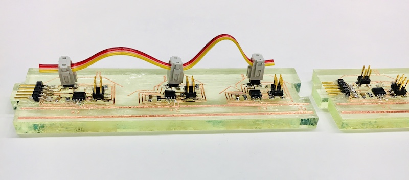
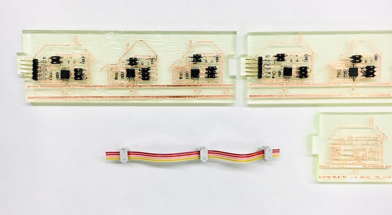
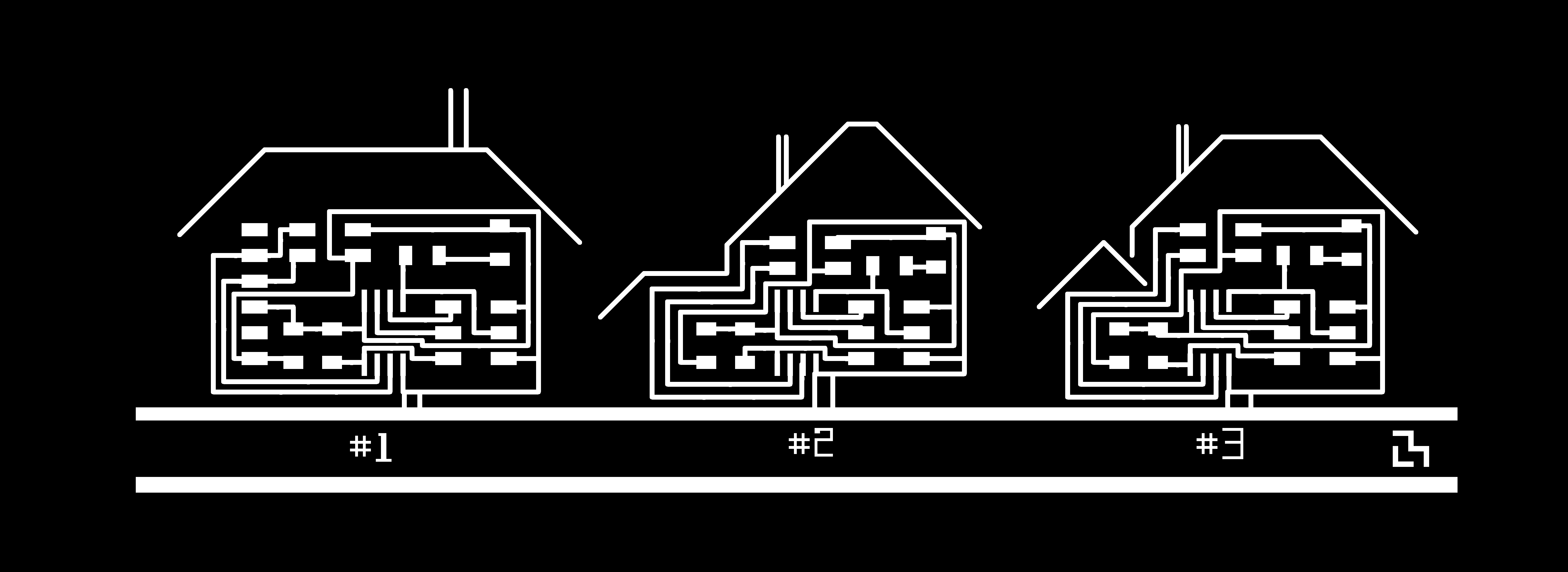
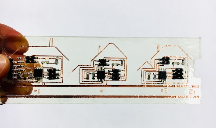
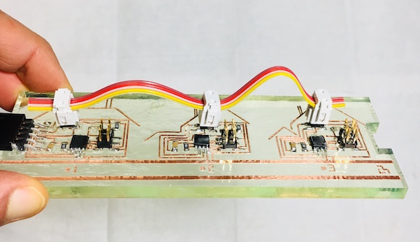
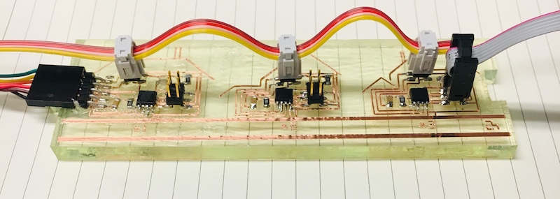
The network of nodes I made this week is simple. The nodes are connected in a daisy-chain configuration by a serial bus. They receive and transmit messages using the RS-232 communication protocol.
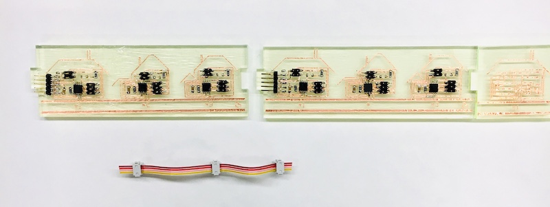
Each node in this network has an address: 1, 2, 3, … and each node receives each message sent along the daisy chain. The messages are addressed to specific nodes (the simple messages are addresses). Upon receiving a message, a node flashes its LED. If the message is addressed to it, the node, flashes its LED twice and sends out a message of acknowledgement (“ACK from node _”).
RS-232 only requires a bus to have transmit (Tx) and receive (Rx) connections. The bus connecting this network also has GND and VCC lines.
code:
MAKING PROCESS
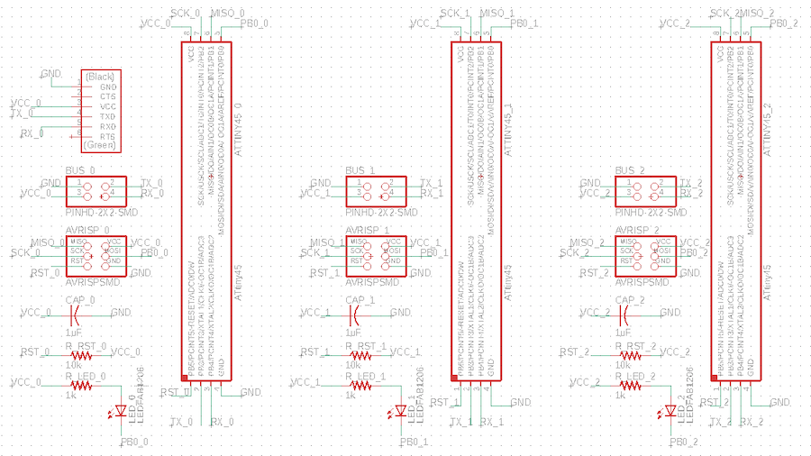
I designed my nodes in the Eagle software.
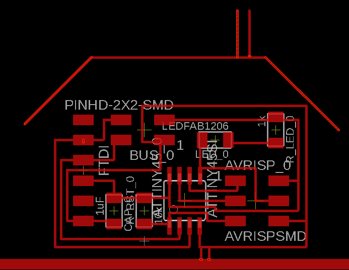
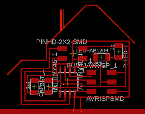
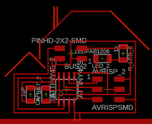
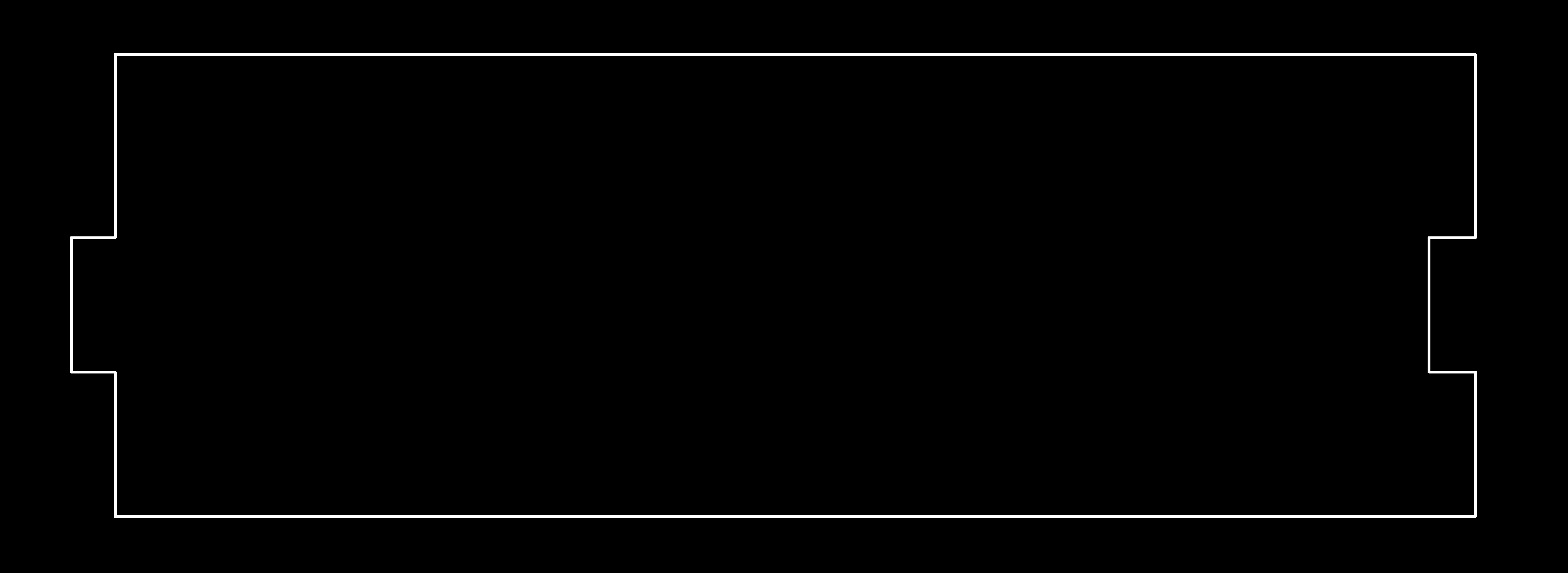
And exported 2 PNG files: a board outline and interior traces.
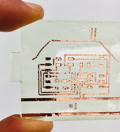
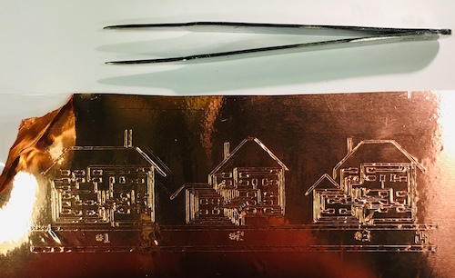
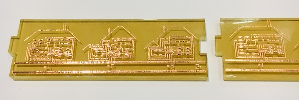
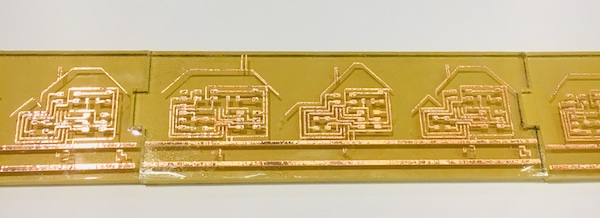
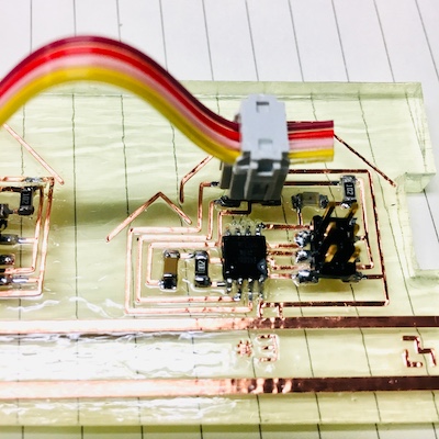
The circuit boards were created with a (Roland) vinyl cutter. Océane and Lizbeth led a wonderful demonstration on how to do this.
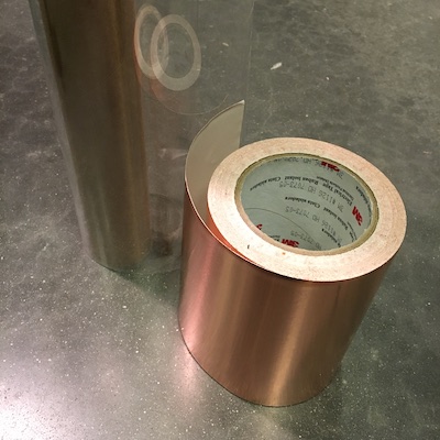
Material: Copper sticker sheet applied to acetate sheet.
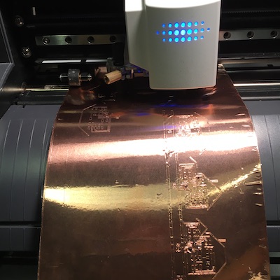
Traces cut with the vinyl cutter in this way should be >= 18mil thick. My initial cuts failed because my traces were not thick enough, so I updated my Eagle board and exported the files again.
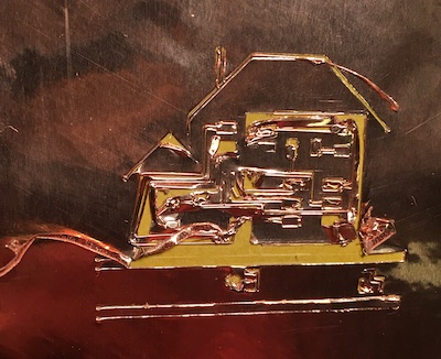
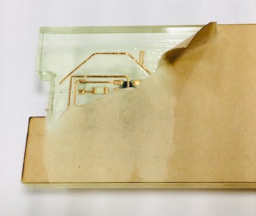
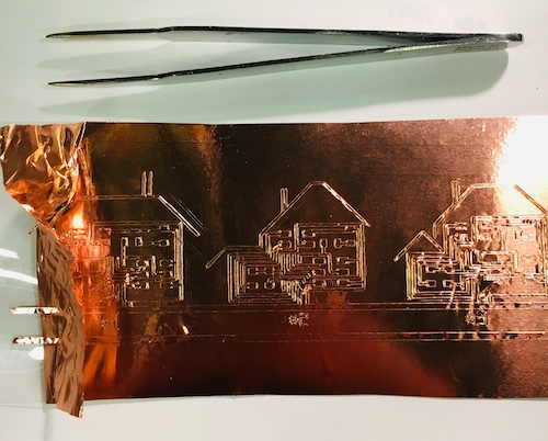
After the traces were successfully cut, there were hours of “weeding”: The process of peeling away the unneeded copper with tweezers.
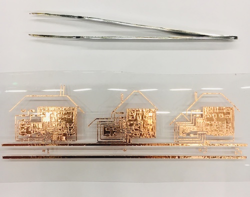

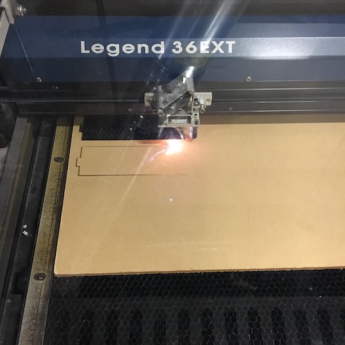
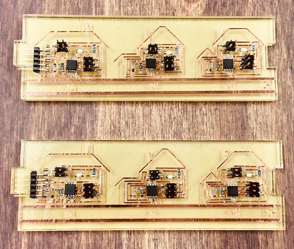
I used the laser cutter to cut out the outline for the board on acrylic.
I attached the traces to the acrylic with superglue.
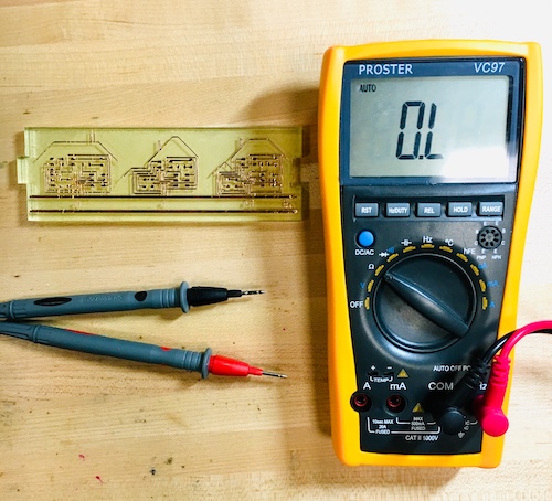
The traces looked messy and like they likely had shorts, so I used a multimeter to confirm that they did not. I continued to use a multimeter throughout the soldering process to find my shorts and remove them with a copper braid.
I spent several hours soldering.
When I first tried to program the nodes, I realized the traces were too delicate. Connecting the wires to the headers started to tear up the solder.
I tried to find an epoxy or resin to coat the board with, but when I was unable to I tried a collection of glues.
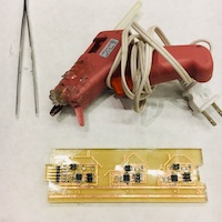
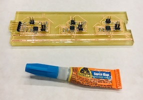
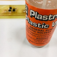
The best option was a plastic solvent cement that my lab (City Science) used to glue legos together. It is very toxic.
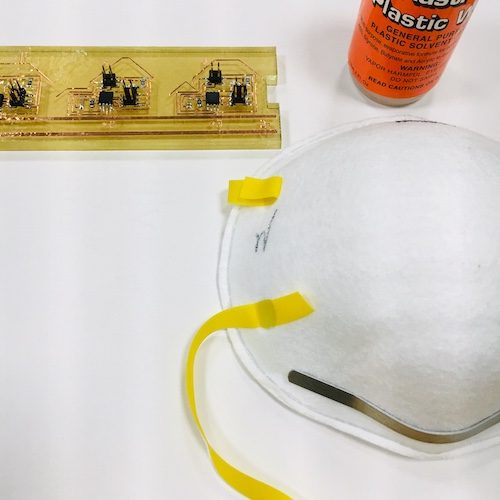
The boards were then ready to program.
PROGRAMMING THE NODES
code:
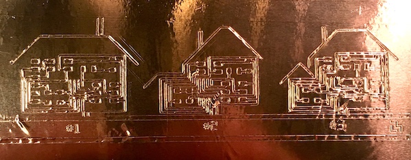
I reused Neil’s code, though modified the node_id’s and the messages the nodes responded with. I individually programmed each node with this same code, modifying the node_id each time so that each house node would have a unique node_id as its “address”.
Process:
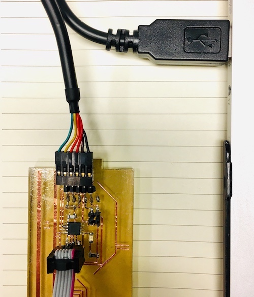
I plugged my board’s FTDI header into the computer and found the device name.
python -m serial.tools.list_ports
Device name is /dev/cu.usbserial-FTFMHTQC
To compile the code and program the boards (with the AVRISP header connected to my computer and the node):
      make -f hello.bus.45.make
      make -f hello.bus.45.make program-avrisp2
I communicated with the boards by using my computer as a “master” node to send messages to the house nodes. I used term.py as the serial interface to do this.
python term.py /dev/cu.usbserial-FTFMHTQC 9600
I sent the nodes messages as their addresses (1, 2, ...) for them to respond to with ACK’s. They flash their LEDs for all messages they see, and flash twice when the message is for them.
Programming issues:
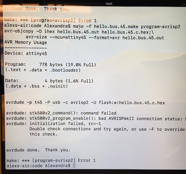
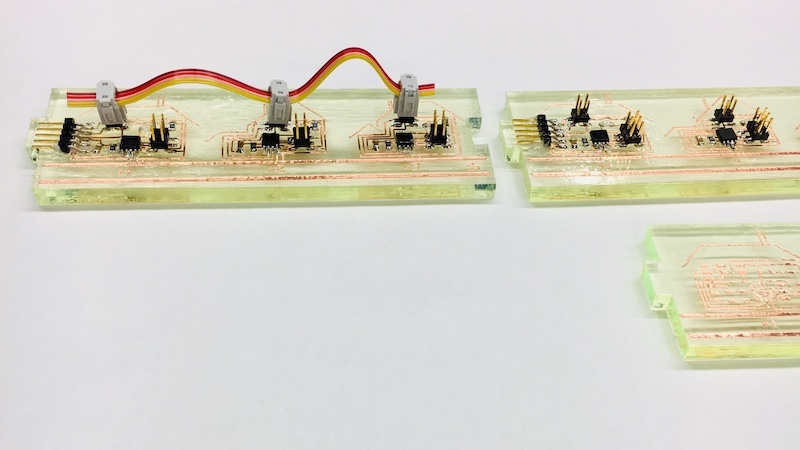
There were programming errors that led to hardware debugging.
Some nodes had short circuits. I was able to cut back shorted traces with a blade to fix one node. Another node’s short circuit had been glued in place.
Yet enough nodes were functioning to have a network of house nodes.